
151
10
PracticalStereoRendering
Matthew Johnson
Advanced Micro Devices, Inc.
This chapter discusses practical stereo rendering techniques for modern game
engines. New graphics cards by AMD and Nvidia enable application developers
to utilize stereoscopic technology in their game engines. Stereo features are ena-
bled by middleware, driver extensions, or the 3D API itself. In addition, new
consumer-grade stereoscopic displays are coming to the market, fueled by the
excitement over 3D movies such as Avatar and How to Train Your Dragon.
10.1IntroductiontoStereo3D
In the real world, people use a variety of methods to perceive depth, including
object size, shadows, object occlusion, and other cues. Additionally, having two
eyes allows a person to perceive depth by generating a pair of images that are
subsequently merged into one image by the human brain. This is called binocular
vision.
The eyes have several mechanisms to focus and merge a stereoscopic pair
into one image:
■ Binocular disparity. The horizontal displacement between the eyes (called
the interaxial or interpupillary distance) introduces a shift between the imag-
es viewed by the eyes. This can be observed, for example, by focusing on an
object and alternately closing the left and right eye—the focused object is
shifted left and right.
■ Convergence. Convergence arises through the ability to rotate the eyes in-
ward to help focus on an object in an effort to merge the stereo pair. This of-
ten causes discomfort for the person, especially if the object is very close.
The opposite of this is divergence, but human eyes are only capable of slight-
ly diverging.
152 10.PracticalStereoRendering
■ Accommodation. Accommodation is the ability of the eye to focus on an ob-
ject by changing the curvature of the lens. Accommodation is often simulated
today even without stereo. For example, game engines that utilize depth-of-
field algorithms often apply a postprocess blur to objects that are deemed out
of focus.
The stereo algorithm described in this article takes advantage of binocular dispar-
ity to achieve the desired stereo effect.
10.2OverviewofStereoDisplays
There are several types of new stereo displays coming to the market. In the past,
these monitors and projectors typically used proprietary display formats to en-
code stereoscopic data, requiring special software and hardware to drive them.
Newer standards, such as Display Port 1.2 and HDMI 1.4, define several required
stereo formats that must be supported by qualifying hardware. The availability of
common specifications simplifies the implementation of stereo for middleware
and application vendors.
The principle challenge in stereo displays is ensuring that the correct image
is transmitted to the correct eye. Anaglyph glasses are a relatively low-cost solu-
tion to this problem. These glasses are designed to filter certain colors so that
each eye can receive only one set of colors. If any of those colors “bleed” into the
other eye, a ghosting artifact can occur. In addition, it is difficult to get a full
range of colors across the spectrum. Despite this fact, anaglyph glasses are con-
stantly improving with certain technologies or color combinations that diminish
these shortcomings.
Because of the disadvantages of anaglyph glasses, newer stereo displays are
often bundled with liquid crystal shutter glasses. These glasses work by alternat-
ing between one eye and the other (by applying a voltage to one of the lenses to
darken it) at a fast refresh rate. Shutter glasses have the advantage of supporting
the full color range.
The main disadvantage with shuttering is the flickering that is often observed
at lower refresh rates. This is becoming less of an issue as higher refresh rate dis-
plays become available. For an HDMI 1.4-compliant stereo display, the high-
definition mode
1
280 720 (720p) is supported up to 120 Hz (or 60 Hz per eye),
while the
1
920 108
0
mode (1080p) is supported at 48 Hz (24 Hz per eye). A
24-Hz refresh rate is considered the baseline in television and interactive
media.
10.3IntroductiontoRenderingStereo 153
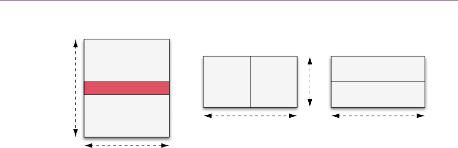
Figure 10.1. Common stereo display formats. Frame packing, side-by-side, and top-
bottom are all supported by HDMI 1.4.
Several standards exist for storing the stereo pair content to be delivered to
the target display. Frame packing is the most promising format, enabling applica-
tions to use full-resolution back buffers for both the left eye and right eye.
A few of the common stereo display formats are shown in Figure 10.1. Some
formats, such as side-by-side (half) and top-bottom (half), can be generated with
the same display bandwidth and resolution by using half the horizontal or vertical
resolution per eye.
10.3IntroductiontoRenderingStereo
The goal of the game engine is to generate the left-eye and right-eye images and
render them to a stereo-capable display surface. The displacement between each
projected point caused by rendering to the left eye and right eye is called
paral-
lax
. The displacement in the horizontal direction is called horizontal parallax. If
the left and right eyes are rotated towards the focus (look-at) point,
vertical par-
allax
can occur. Since convergence causes discomfort in the eye, this method
(known as “toe-in”) is avoided.
The difference between the three horizontal parallax modes is shown in Fig-
ure 10.2. Objects with positive parallax appear behind the screen, while objects
with negative parallax appear in front of the screen. When a point is projected to
the same position on a plane for the left eye and right eye, it is known as zero
parallax. The goal for positioning the camera is to have the scene or object of
focus centered at zero parallax, with the front of the object at negative parallax
and the back of the object at positive parallax, while ensuring that, at most, the
Frame packing
Side-by-side (half) Top-bottom (half)
Left
Right
(Optional) Blanking
Right
Right
Left
Left
w
w
w
h
h
154 10.PracticalStereoRendering
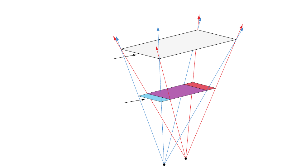
Figure 10.2. A stereo camera configuration utilizing two parallel asymmetric frustums.
At zero horizontal parallax, the left eye and right eye overlap completely.
negative parallax does not exceed the interaxial distance. Another alternative is to
avoid negative parallax completely and set the near plane distance equal to the
zero-parallax distance.
In real life, eye convergence introduces vertical parallax, but this can also
cause eye discomfort. To avoid vertical parallax, the frustums should not be ro-
tated to the same look-at point. Using parallel symmetric frustums avoids vertical
parallax, but at the cost of introducing excessive negative parallax. Therefore, the
preferred way of rendering stereoscopic scenes is utilizing two parallel asymmet-
ric frustums.
10.4TheMathematicsofStereoViewsandProjection
The first step in rendering a scene for stereo is to calculate the desired horizontal
parallax. In this chapter, we assume a left-handed coordinate system (positive
z is
“behind” the screen) in camera space.
N
egative horizontal parallax
Zero horizontal parallax
Positive horizontal parallax
Left
Right
10.4TheMathematicsofStereoViewsandProjection 155
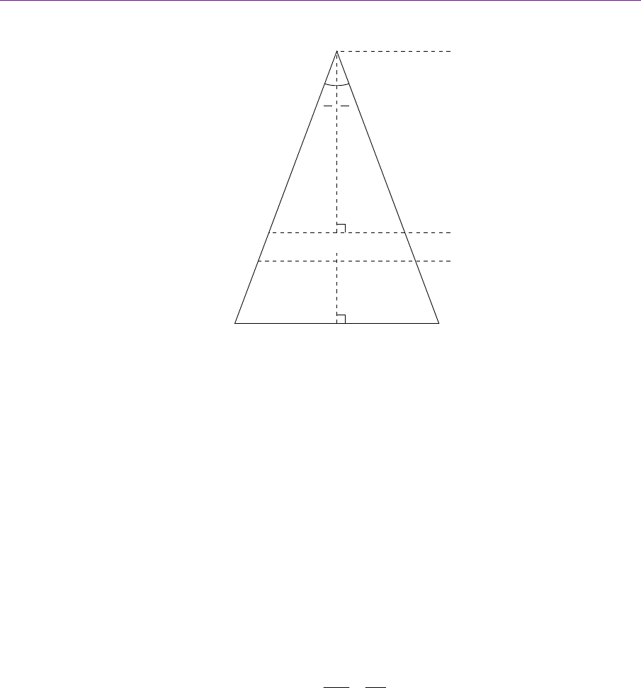
Figure 10.3. The relationship between camera distances and horizontal parallax, based on
the projected view-space point P.
The general rule of thumb is for the interaxial width
a
W
between the eyes to
be equal to 1/30th of the distance to the horizontal zero-parallax plane, where
1.9θ (the angle between the focus point and each eye). This relationship can
be visualized in Figure 10.3. The manufacturers of shutter glasses generally pre-
fer a maximum parallax of 1.5θ
, which comes out to roughly 1/38th the dis-
tance to zero parallax.
As an example, suppose that the bounding sphere of a scene in view space
has center
C and radius 45.0 and that we need to calculate the interaxial distance
necessary to achieve zero parallax at the center of the scene. In view space, the
camera location is
0,0,0 . Therefore, the distance from the camera to the center
of the sphere is
z
C
, and thus
z
zC
. For a maximum parallax of 1.5θ , we have
the relationship
1.5
tan
22
a
W
z
.
So
0.0262
a
W
z
. Thus, one can find the desired interaxial distance given a hori-
zontal parallax distance of zero.
2
θ
2
θ
0
z
n
z
P
a
WInteraxial distance ( )
Horizontal parallax ( )
0
W
Left Right
..................Content has been hidden....................
You can't read the all page of ebook, please click here login for view all page.