
284 17.PlaceholdersbeyondStaticArtReplacement
■ Provide an accurate estimate of the look and behavior of the final asset. This
one is a bit tricky and can be considered a bit more loosely. The idea of “ac-
curate estimate” in terms of look and behavior differs a lot from one project
to another. Using a cylinder with a sphere sitting on top of it might be
enough to picture a character in a real-time strategy game. To express the be-
havior of the final resource, a simple arrow can be added to indicate in which
direction the unit is facing. However, in a platformer or an adventure game,
the placeholder character might need to be a bit more detailed. If the anima-
tions are already available, that character could even be articulated and ani-
mated. The amount of work that needs to be done to correctly represent the
look and behavior of the final asset amounts to the quantity of details re-
quired to understand the placeholder.
■ Can be created or generated rapidly with no particular skill required. By
definition, placeholders are temporary and do not involve detailed work at
all. If creating them becomes a time burden or requires fine tuning, the whole
point of building a placeholder gets somewhat lost. Moreover, if special
skills are required to create the placeholder, such as artistic or programming
skills, the idea of reducing coupling by creating them also gets lost in the
process, since someone depends on the expertise and schedule of someone
else to have the placeholder created. Ideally, everyone on a development
team should be able to create a placeholder within a matter of minutes.
■ Facilitate communication between team members. While a placeholder will
never replace a design document or a good old explanation, it does not nec-
essarily mean it cannot help on the communication side of things. Placehold-
ers have a shape or a surface through which information can be conveyed.
What information to convey and how to do it should be one of the primary
questions when building a placeholder system.
■ Integrate easily in the already existing resource pipeline. One of the im-
portant aspects of a placeholder system is for it to have a small footprint on
production time. This applies to the creation of the placeholder itself but also
to the creation of the system. If integrating placeholders into your 3D pipe-
line requires three months of refactoring, you might want to rethink your
original placeholder idea (or rethink the flexibility of your resource pipeline,
but that’s another discussion).
■ Scalable and flexible enough to work on multiple platforms. Placeholders are
a bit like code. If they’re done correctly, they should be able to scale and
adapt to any kind of platform. This is especially true now, since game studios
have become more and more likely to build games on multiple platforms at
the same time. Some studios have even started working on game engines that
17.2PreachingbyExample:TheArticulatedPlaceholderModel 285
run on PCs, consoles, handhelds, and cell phones alike. Avoid using plat-
form-specific features when creating placeholders, and ensure that the tech-
niques used to generate them can be scaled and adapted to multiple
platforms.
As we conclude this part of the chapter, what remains important to remember
is that taking the time to create a good placeholder system for your game certain-
ly helps development time in the long run. The effects are a bit subtle and hard to
gauge unless you go back to an environment that doesn’t use placeholders effi-
ciently, but it remains there and smooths development time, removing much of
the stress and delays associated with schedule coupling.
17.2PreachingbyExample:TheArticulated
PlaceholderModel
The previous discussion wouldn’t be very valuable without an example to back it
up. To further develop the topic of placeholders, the remainder of this gem fo-
cuses on a placeholder system that generates articulated (and therefore animated)
placeholder meshes from animation skeletons. The reasoning behind this particu-
lar choice of placeholder is that animation skeletons are often reused throughout
multiple models that have roughly the same shape or are developed using proto-
type geometry, while the final model will be completed many months later dur-
ing development [Lally 2003]. Various approaches can be used to fill in the
missing animated meshes that have yet to be produced. The first approach is to
reuse the animation rig or prototype model geometry as a placeholder. This is a
correct approach since the placeholder nature of the rig geometry is easily recog-
nizable and the rig remains an acceptable visual representation of the final mesh.
However, the rig geometry is often very simple and provides a poor approxima-
tion of the required rendering, physics, and animation costs of the final resource.
Therefore, the idea remains good for prototype development but has its limita-
tions for production purposes. Another approach is to reuse a previously modeled
mesh that has the same skeleton. Unfortunately, as we’ve discussed earlier, this
can create confusion and should be avoided.
To bypass the previously mentioned shortcomings, we present a method that
generates a placeholder mesh using implicit surfaces based exclusively on an an-
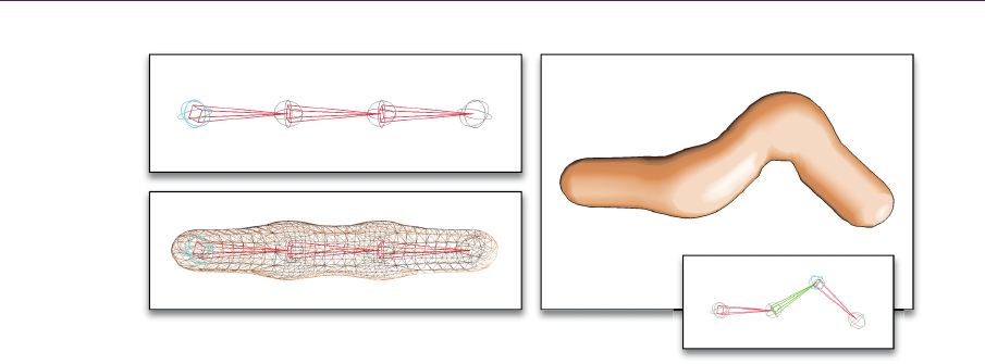
imation skeleton, as shown in Figure 17.1. Once the mesh is generated, the skele-
ton’s bone weights are automatically assigned to the mesh vertices, which can
then be animated using standard skeletal animation skinning methods. Every step
286 17.PlaceholdersbeyondStaticArtReplacement
Figure 17.1. Depiction of the articulated placeholder generation technique. (a) The ani-
mation skeleton is used as the basis for the (b) mesh generation using implicit surface. (c)
The mesh is skinned to the skeleton, which can then be animated, animating the articulat-
ed placeholder mesh itself.
employs popular computer graphics techniques that are very easy to implement
and well documented. Special care was also put into ensuring that the placehold-
er construction uses popular rendering engine infrastructures when possible to
further reduce the time required to integrate the system into a production pipe-
line. The generation process is sufficiently detailed to ensure that a user with no
prior experience with skeletal animation and implicit surface generation can still
build the system. In this regard, advanced users can feel comfortable skipping
some of the entry-level explanations.
SkeletonConstruction
The first step is to create the animation skeleton itself. The animation skeleton is
the root of a widely used animation technique called “skeletal animation” [Kavan
and Žára 2003], which is arguably the most popular animation technique current-
ly used in the videogame industry.
Skeletal animation is based on a two-facet representation of an animated 3D
mesh: the skin and the skeleton. The skin is the visual representation of the object
to be animated, which consists of a surface representation of the object. This sur-
face is often, but not always, made of tightly knit polygons called a mesh. The
other part of skeletal animation is the skeleton, which is a representation of the
underlying articulated structure of the model to animate. By animating the skele-
ton and then binding the surface to it, it is possible to animate the surface itself.
(a)
(b)
(c)
17.2PreachingbyExample:TheArticulatedPlaceholderModel 287
Before delving into the intricacies of the latter part of the process, we first begin
by looking at the construction of the skeleton.
The skeleton consists of a hierarchical set of primitives called bones. A bone
is made up of a 3D transformation (position, scale, and orientation) and a refer-
ence to a parent bone. (The parent bone is optional, and some bones, such as the
topmost bone of the hierarchy, have no parent.) The parent-child relationship be-
tween bones creates the skeletal hierarchy that determines how a bone is trans-
formed. For example, if an upper arm bone is rotated upward, the forearm bone
rotates upward accordingly since it is attached (through the hierarchy) to the up-
per arm bone.
Even if the final bone animation only has one transformation, the bones, dur-
ing the animation creation, must have two separate transforms: The bone-space
transform
1
B
and the pose transform P. Since these transforms apply to a partic-
ular bone of the skeleton, we identify the bones as the j-th bone of the skeleton,
and denote the transforms by
1
j
B
and
j
P
. These transforms can be represented as
a
4
4 homogeneous matrix having the general form
rot trans
1
jj
j
T
T
T
0
, (17.1)
where
rot
j
T
is a
3
3 rotation matrix, 0 is a
1
3
zero vector, and
trans
j
T
is a
3
1 posi-
tion vector. Another approach, which is more compact, is to represent
j
T
as a
quaternion-translation pair. This, however, prevents the inclusion of a nonuni-
form scale in the transformation, which might be a problem if it is needed.
The bone-space transform
1
j
B
is the inverse of the bone’s transformation in
world coordinate space when it is in its initial pose, also known as the bind pose
(the pose in which the skeleton was created before being animated). The pose
transform
j
P
is the combination (product) of a given bone’s parents’ transforms
and its own local transformation. The matrices
j
P
and
1
j
B
, and their effects on a
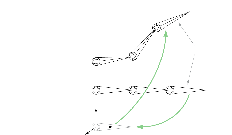
given bone are represented in Figure 17.2. The final and unique transformation
j
M
for a given bone is found by multiplying the bone-space and pose transfor-
mations:
1
j
jj
M
PB
. (17.2)
The matrix
j
M
is used later to transform the mesh vertices according to the ani-
mation during the skinning process.
At this point, you should have the required components and mathematics to
build your own animation skeleton. However, it remains a hierarchy of 3D trans-
288 17.PlaceholdersbeyondStaticArtReplacement
Figure 17.2. Bone j from the skeleton is brought to the origin by the transformation
1
j
B
.
The transformation
j
P
then transforms the bone j to its animated pose.
formations, and this can be rather hard to visualize. To help in viewing your skel-
eton and ensuring that your transformations are applied correctly, it is suggested
that you visually represent a skeleton as a set of bones and joints, where the dif-
ference between the translations for two transformation matrices (the bones) are
modeled as line segments, and the connections between bones (the joints) are
visualized as spheres. If you already work in a development environment, this
representation is probably already built into your 3D modeling software or into
your engine’s debugging view.
PlaceholderMeshGenerationwithImplicitSurfaces
With the skeleton constructed, the placeholder mesh can now be created. The
objective here is to find a technique that generates the mesh in such a way that it
visually resembles the desired final asset. Moreover, we’d like the technique to
generate a surface that can be easily animated to emulate the final asset’s behav-
ior. On top of this, the technique must provide control over the amount of geome-
Animated pose skeleton
Bind pose skeleton
World space
Bone j
x
y
z
j
P
1
j
B
−
..................Content has been hidden....................
You can't read the all page of ebook, please click here login for view all page.