Appendix 3A: Steam Turbine Power Plant Theory Applicable to Combined Cycle and ‘Solo’ (as Competition to Gas Turbine Cycle) Operation13
Rankine Cycle
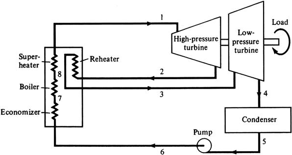
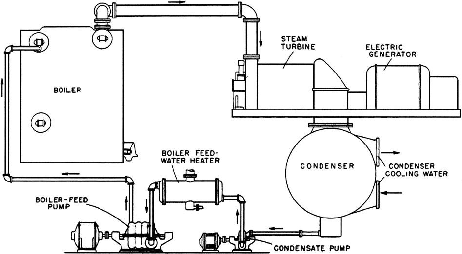
The Rankine cycle is the most common cycle in power generation. Figure 3A–1 is a simplified Rankine cycle.
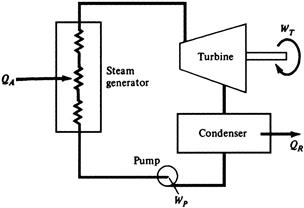
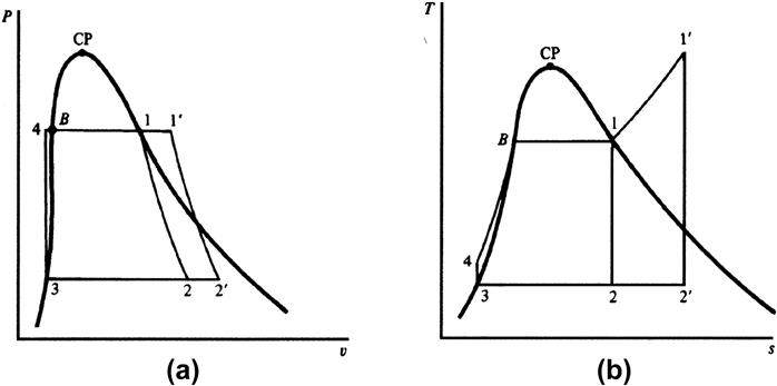
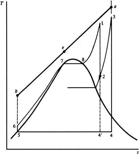
Figure 3A–2 shows the ideal Rankine cycle. Cycle 1234B1 is a saturated Rankine cycle (saturated vapor enters the turbine). Cycle 1′2′34B1′ is a superheated Rankine cycle.
The following assumptions are made:
• The cycles shown are internally irreversible.
• Processes through the turbine and pump are adiabatic irreversible (see the vertical on the T-s diagram).
• 4B11′ is a constant pressure line.
• 1-2 or 1′-2′ is an adiabatic reversible expansion (exhaust is in two phases).
• 2-3 or 2′-3′ is a constant-temperature, two-phase mixture with constant-pressure heat rejection in the condenser.
• 3-4 is adiabatic reversible compression by the pump of saturated liquid at condenser pressure 3 to subcooled liquid at steam generator pressure 4. Note: 3-4 is vertical on both the P-V and T-S diagrams (incompressibility and the pump is adiabatic reversible).
• 4-1 or 4-1′ is a constant-pressure heat addition in the steam generator. 4-B-1-1′ is a constant pressure line on both diagrams.
• 4-B is subcooled liquid to saturated liquid at B at constant temperature and pressure (two-phase mixture).
• B-1 in the steam generator is the boiler or evaporator.
• 1-1′ indicates heating saturated vapor at 1 to 1′ (superheat).
Heat added: qA = h1 – h4 Btu/lbm (or J/kg)
Turbine work: wT = h1 – h2 Btu/lbm (or J/kg)
Heat rejected: |qR| = h2 – h3 Btu/lbm (or J/kg)
Pump work: |wp| = h4 – h3
Net work: 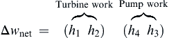 Btu/lbm (or J/kg)
Thermal efficiency: ![]()
For small units: P4 ≈ P3, h3 h3 ≈ h4
Therefore, pump work is small compared with turbine work,
In modern plants, this assumption is not true. The term P4 may be 1000 psi (70 bar) and P3 about 1 psi (0.07 bar).
To calculate pump work from h3 (saturated liquid at P3),
Pump work ≈ Change in flow work, or
Calculate h4 from subcooled liquid tables at T4 and P4 (assume T3 = T4).
Reheaters
Reheating is illustrated in Figures 3A–3 and 3A–4.
We make the following assumptions:
Note: Line ab = primary coolant in a counterflow steam generator (primary heat source = combustion gases from the steam generator).
One stage of reheat works economically. Two stages are not a good return on investment.
The steam may be reheated in the steam generator or a separate heat exchanger reheater.
The reheat cycle contains two turbine work terms and two heat addition terms.
Figure 3A–5 shows cycle efficiency versus the ratio of P2/P1 (reheat pressure/initial pressure).
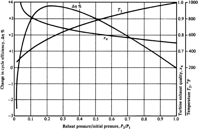
If the reheating pressure is too close to the initial pressure, the increase in cycle efficiency is minimal, since only a small portion of heat is added at high pressure. For optimum reheating, P2/P1 is 20–25%.
Lowering reheat pressure causes further efficiency decrease.
Exhaust steam is drier in a reheat cycle. A superheat-reheat plant is designated P1/T1/T3 (e.g., 2500 psi/°F/1000°F), see Table 3A–1. Note efficiency rises with reheating and drops with non-ideal fluids.
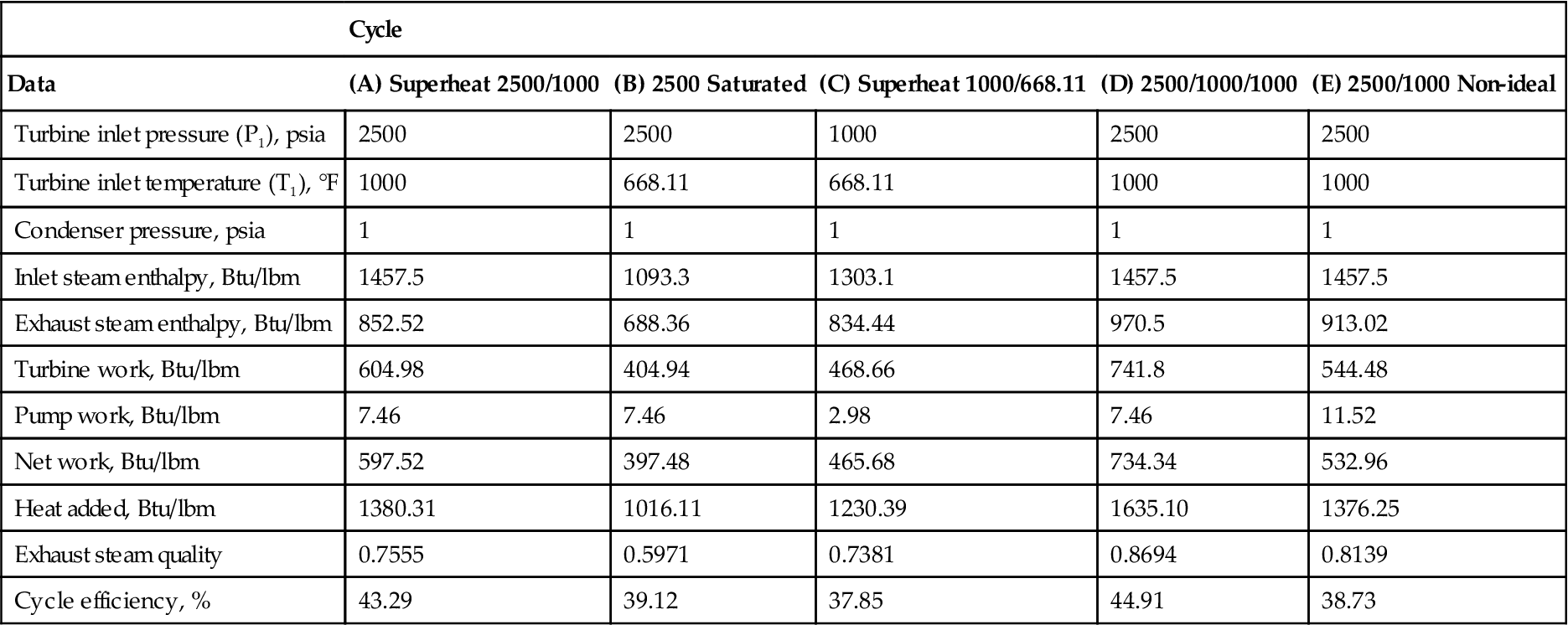
TABLE 3A–1
Steam Power Plant Performance Comparison [3-3]
| Cycle | |||||
| Data | (A) Superheat 2500/1000 | (B) 2500 Saturated | (C) Superheat 1000/668.11 | (D) 2500/1000/1000 | (E) 2500/1000 Non-ideal |
| Turbine inlet pressure (P1), psia | 2500 | 2500 | 1000 | 2500 | 2500 |
| Turbine inlet temperature (T1), °F | 1000 | 668.11 | 668.11 | 1000 | 1000 |
| Condenser pressure, psia | 1 | 1 | 1 | 1 | 1 |
| Inlet steam enthalpy, Btu/lbm | 1457.5 | 1093.3 | 1303.1 | 1457.5 | 1457.5 |
| Exhaust steam enthalpy, Btu/lbm | 852.52 | 688.36 | 834.44 | 970.5 | 913.02 |
| Turbine work, Btu/lbm | 604.98 | 404.94 | 468.66 | 741.8 | 544.48 |
| Pump work, Btu/lbm | 7.46 | 7.46 | 2.98 | 7.46 | 11.52 |
| Net work, Btu/lbm | 597.52 | 397.48 | 465.68 | 734.34 | 532.96 |
| Heat added, Btu/lbm | 1380.31 | 1016.11 | 1230.39 | 1635.10 | 1376.25 |
| Exhaust steam quality | 0.7555 | 0.5971 | 0.7381 | 0.8694 | 0.8139 |
| Cycle efficiency, % | 43.29 | 39.12 | 37.85 | 44.91 | 38.73 |
Regeneration
Figure 3A–6 illustrates the Rankine cycle. The working fluid is represented by 4B1234, where
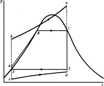
a-b = primary coolant in a counterflow steam generator (combustion gases).
c-d = heat sink fluid in a counterflow heat exchanger (condenser cooling water or air).
Line a-b too close to 4-B-1 implies that the T between the primary coolant and working fluid is small, which implies that irreversibility is small but the steam generator has to be large; expensive.
Line a-b to far from 4-B-1 implies that irreversibility is large, efficiency is low, and the steam generator is small.
Maximum irreversibility occurs at the maximum distance between a-b and 4-B. This distance is minimum at point B. So irreversibility is minimized if the fluid is added to the steam generator at point B not 4. Regeneration helps this minimization by adding heat from the expanding fluid in the turbine to the compressed fluid before heat addition.
Feedwater Heating
With feedwater heating at point 4, heat is added in several heat exchangers by steam bled from the turbine at selected stages. Power plants generally use between five and eight feedwater heating stages.
Efficiency and Heat Rate of Power Plants
Gross efficiency is calculated using the power (in MW) produced before supplying power to the plant’s internal equipment (pumps, compressors, and so forth).
Net efficiency is calculated based on the net power of the plant (the gross power minus the power needed for internal plant equipment).
Cogeneration
The term cogeneration means that electricity and steam (heat) are generated at the same time. Process plants and small municipalities often use cogeneration, as they can usually get better return on investment (ROI) on the process than a utility.
Cogeneration is useful only if it saves money over separate generation of electricity and steam.
Cogeneration efficiency: ![]() where
where
Enthalpy of steam entering the process—enthalpy of process condensate.
For separate electricity and steam generation, the heat added per unit of total energy is
The equation for combined efficiency for separate generation (from previous equations) is
If ηco > ηc, then cogeneration offers a better ROI.
Types of Cogeneration
There are two main kinds of cogeneration cycle: a topping cycle and a bottoming cycle.
The topping cycle really is the only economic cycle of the two. The main heat source generates high-enthalpy steam and electricity. Low-enthalpy steam is taken from an intermediate turbine stage or the turbine exhaust for process requirements. If the steam is taken from the turbine exhaust, this is called a back-pressure turbine.
The range of pressures for process steam varies and generally is on the order of 0.5 bar to 40 bar.
The common subdivisions for types of topping cycle plant are
• Steam electric plant with steam extraction from a condensing turbine (note Figure 3–15).
• Steam electric power plant with a back-pressure turbine.
• Gas turbine power plant with waste heat recovery and a steam generator (boiler).
• Combined-cycle gas turbine plus steam turbine plant (steam turbine can be back-pressure or condensing type).
The bottoming cycle is not very efficient. High-enthalpy heat is used directly for process needs (e.g., cement manufacture), and low-enthalpy waste heat is used to generate electricity.
Steam Turbine Basic Components and Main Systems
In a steam turbine, high-pressure, high-temperature steam expands to increase the steam’s kinetic energy at the expense of its original pressure energy. That kinetic energy is used to turn the rotor and produce mechanical energy as torque and rotor speed increase.
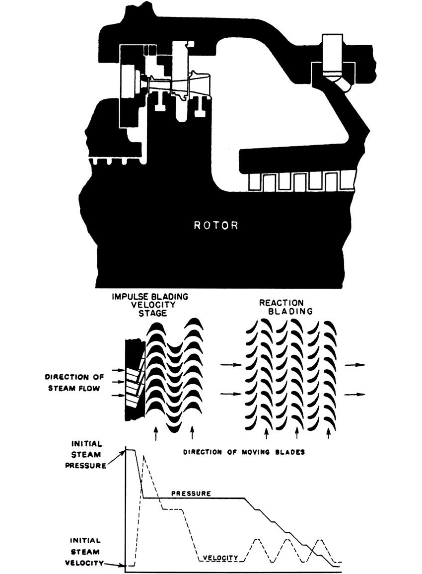
There are two main kinds of steam turbine: impulse and reaction. The bulk of steam turbines today are reaction turbines. In impulse turbines, the flow momentum changes as a steam jet pushes the rotor blades forward. In reaction turbines, a reaction force is felt by the moving blades as steam flow accelerates through a decreasing cross-sectional area.
Figures 3A–7 and 3A–8 illustrates a turbine with impulse blading. It has one velocity-compounded stage where the velocity is reduced in two steps through two rows of moving blades, as the pressure stays constant.
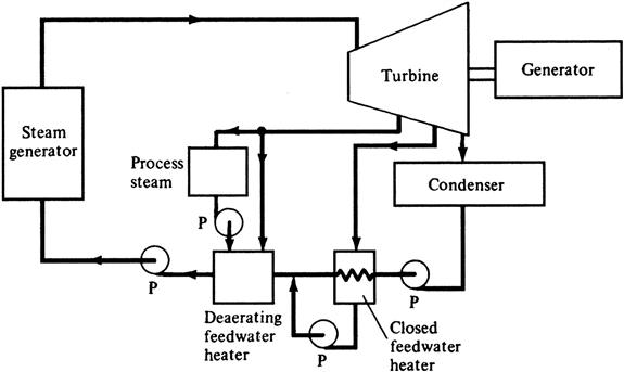
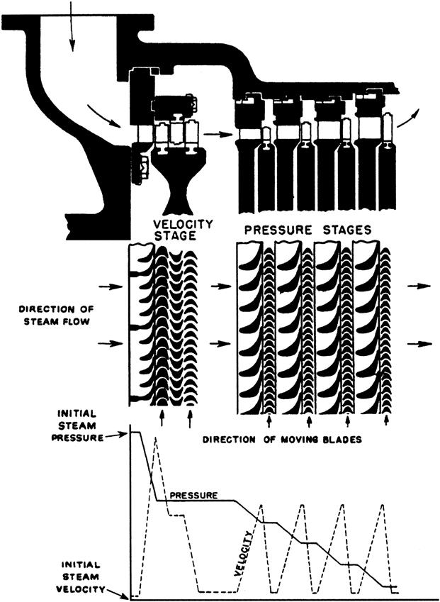
Figure 3A–9 illustrates a reaction turbine with one velocity compounded impulse stage, where a large pressure drop occurs.
Steam Turbine Components
The block diagram Figure 3A–10 illustrates the main mechanical components in a basic steam turbine. Steam turbines that deliver between 40 and 60 MW usually are single-cylinder machines (see Figure 3A–11). For larger steam turbines, more cylinders are used to extract the steam’s energy.
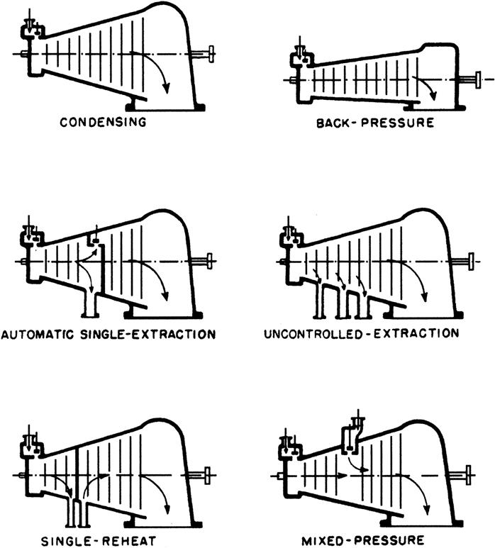
Single-Cylinder Turbines
The two main subdivisions here are condensing and back-pressure (noncondensing) turbines. Automatic extraction turbines allow part of the steam to be drawn off at intermediate stage(s), while the rest of the steam is exhausted to a condenser. These turbines use controls and valves to get constant pressure of extraction steam during conditions of varying load and extraction demand. Uncontrolled extraction (pressure varies at extraction points with load) steam is used to add heat in feedwater heaters.
Some plants add high-pressure noncondensing turbines to increase capacity. The added turbines are called topping or superposed units.
Nozzles14
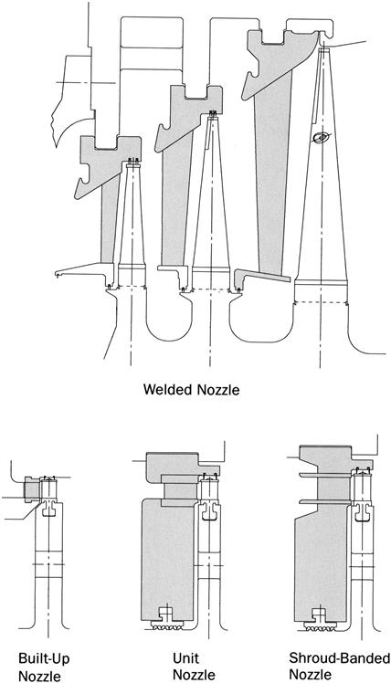
Nozzles, together with blades, play an important role in achieving the high efficiency of a turbine. Nozzles are designed to attain the highest thermal efficiency. They are made of 12% or 18% chrome and 8% nickel stainless steel and have excellent mechanical strength and erosion resistance. The diaphragm in which the nozzle is built is split at the horizontal centerline and the spring-backed labyrinth packing is fitted to minimize steam leakage. Four types of construction are standard, as shown in Figure 3A–12, each of which has its own application range based on specific operating conditions.
Blades
Blades are designed based on accumulated aerodynamic data from various tests and research. The blades are subjected to a large centrifugal force and an exciting force. The blades are made of 12% or 17% chrome and 4% nickel stainless steel and have excellent mechanical strength and damping properties. If necessary, erosion shields made of Stellite are used in the last stages of the condensing turbines to protect the leading edges of the blades from moisture erosion.
Compound Turbines
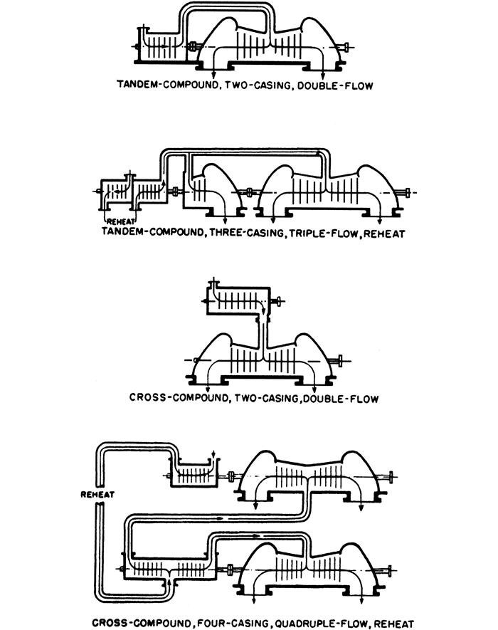
Compound turbines have more than one cylinder: one high pressure and one low pressure. The low-pressure cylinder generally is of the double-flow type to handle a large volume of low-pressure steam. The turbine blades are limited in length by design and the double-flow design adds potential for steam flow. Large plants have more than two cylinders: an intermediate-pressure cylinder and four low-pressure cylinders are not uncommon.
If the cylinders are on one shaft, the arrangement is termed a tandem compound. If they are on more than one shaft, the arrangement is termed a cross compound (see Figure 3A–13).
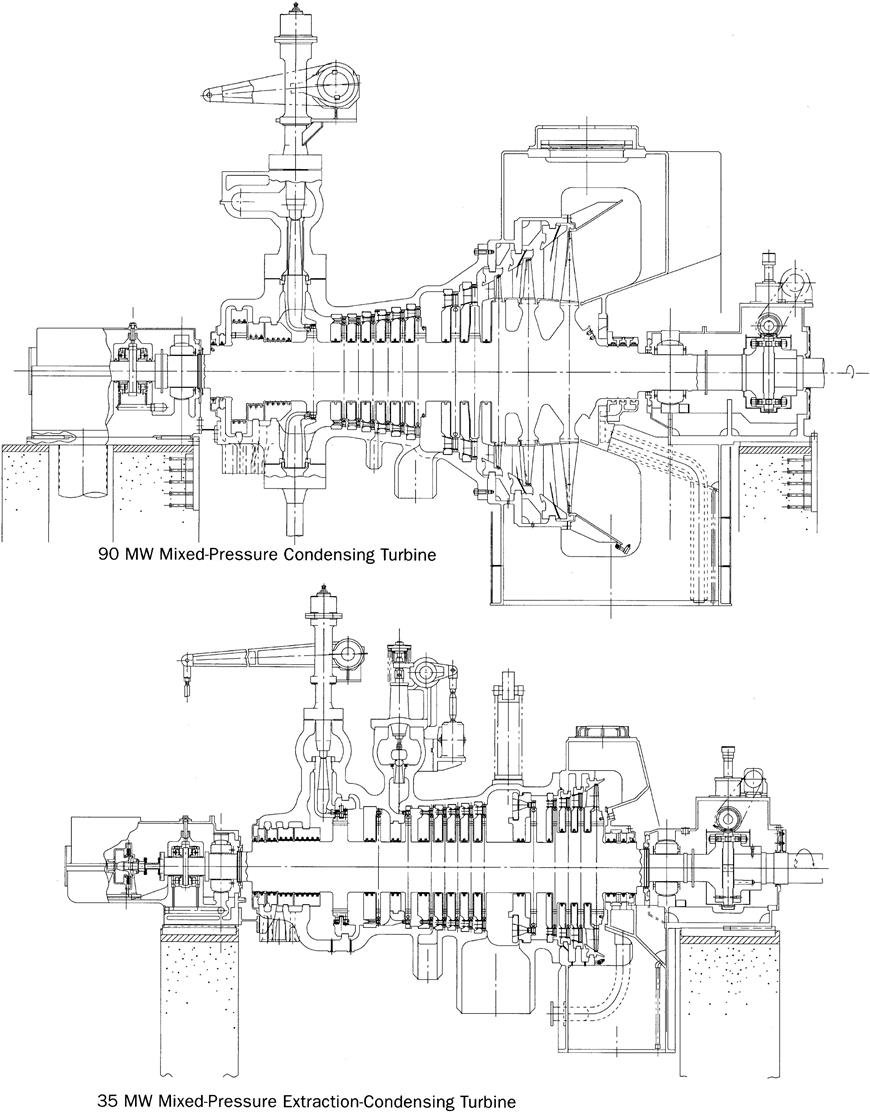
Condensing Turbines
Straight-condensing turbines (Figure 3A–14) are advantageous, especially when large quantities of a reliable power source are required or an inexpensive fuel, such as a process by-product gas, is readily available. To improve plant thermal efficiency, steam usually is extracted from the intermediate stage of the turbine for feedwater heating.
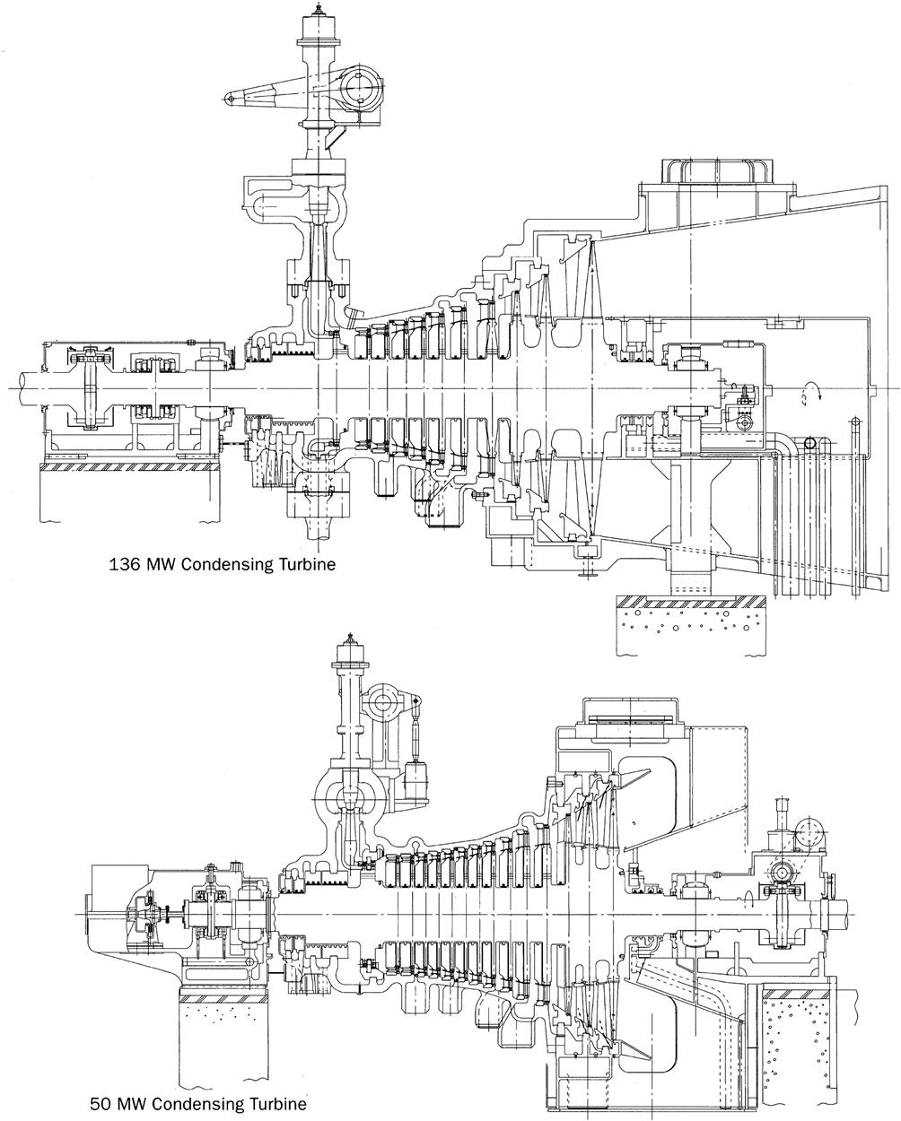
Extraction-Condensing Turbines
Extraction-condensing turbines (Figure 3A–15) generate both process steam and stable electric power. Process steam, at one or more fixed pressures, can be automatically extracted as needed. This type of turbine has the flexibility to satisfy wide variations of process steam at a constant pressure and meet electric power demands.
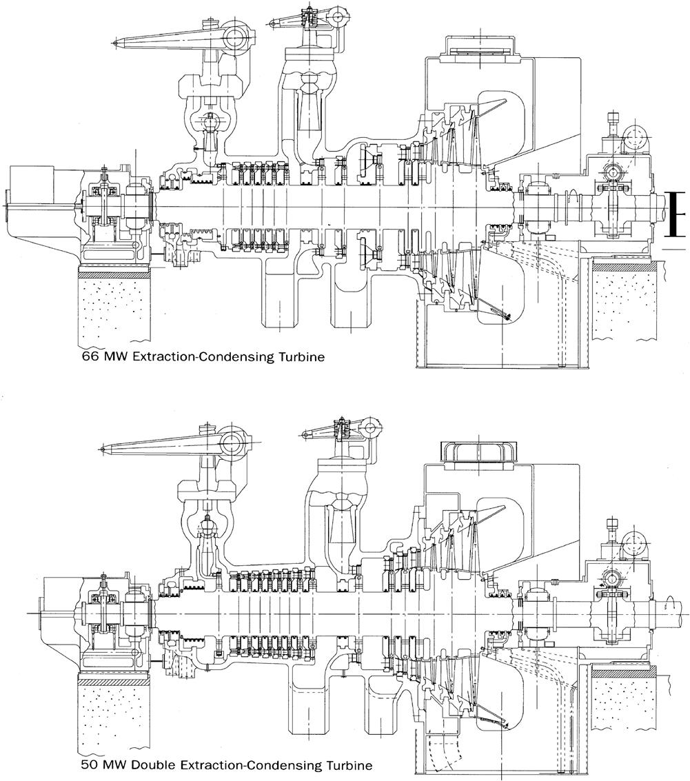
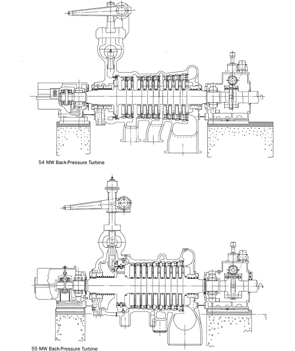
Back-Pressure Turbines
Back-pressure turbines (Figure 3A–16) can be used when a large quantity of process steam is required. The turbine exhaust steam is supplied to the process, and the electric output depends on the demand for the process steam. These turbines also can be used as top turbines to supply exhaust steam to existing units; this improves the entire plant’s thermal efficiency.
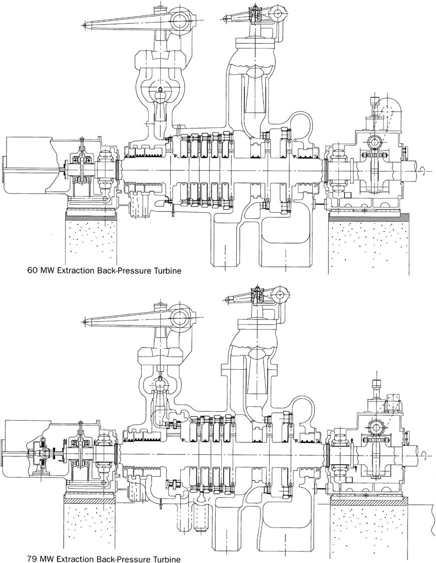
Extraction Back-Pressure Turbines
Extraction back-pressure turbines (Figure 3A–17) can be used when two or more kinds of process steam are required. High-pressure steam is supplied through the extraction openings, and low-pressure steam is supplied as the turbine exhaust. Electric output depends on the demand for process steam.
Mixed-Pressure Turbines
Mixed-pressure turbines (Figure 3A–18) are driven by two or more kinds of steam, admitted independently to the turbine. In applying dual heat sources, the optimum steam condition for each source can be selected. This type of turbine also can be used to combine an existing boiler and a new boiler, which makes it an effective means of improving plant thermal efficiency.
Geared Turbines
Geared turbines (Figure 3A–19) can be applied to smaller power generation units of up to around 40 MW. Compared with direct-coupled turbines, geared turbines have many advantages:
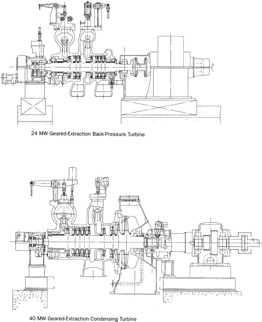
The maximum capacity of geared turbines is increasing every year.
Single-Cylinder Reheat Turbines
Traditionally, nonheat turbines have been used for industrial applications. Recent demands for higher efficiency and larger unit capacity, however, call for reheat turbines in this field. Taking these demands into consideration, single-cylinder reheat turbines have been developed that are applicable in the 75 MW to 200 MW range. Single-cylinder reheat turbines (Figure 3A–20) offer:
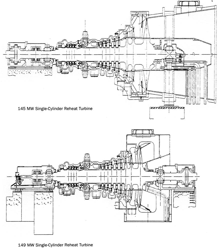
Single-cylinder reheat turbines have been used at conventional boiler-turbine plants and combined cycle plants instead of two-cylinder reheat turbines.
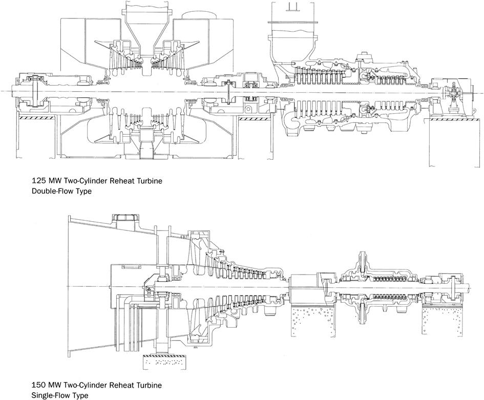
Two-Cylinder Reheat Turbines
Two-cylinder reheat turbines (Figure 3A–21) can be used when a very high efficiency is required for steam turbines larger than 75 MW.
Rotors
The rotor is one of the most important rotating parts of a turbine. Special attention must be paid to the design, materials, and workmanship that go into its construction and the inspections that ensure the highest-quality product. The rotor and the discs, of which critical speed is below the rated speed, are machined completely from a solid forging and are of the flexible type.
Casings
The turbine casing is split at the horizontal centerline. Symmetrical design and simple construction minimize the thermal stress created by temperature changes, and the casing is allowed to expand and contract concentrically with the rotor. The casing is made of cast steel or steel plate, depending on its operating steam conditions.
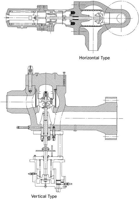
Axial-Exhaust Steam Turbines
Axial-exhaust steam turbines, with the condensers located at the back of the turbines, are effective in reducing the height of the turbine/generator house. This results in a lower initial investment. Customers commonly request that steam turbine suppliers deliver factory-assembled units to reduce the period for and cost of installation.
Steam Turbine Control Systems
Control systems have a minimum of two independent governors. One (the emergency trip) shuts off the steam supply if the turbine overspeeds. The other throttles steam flow to maintain constant speed if the unit is not synchronized to the grid or varies the load in units that are synchronized to the grid.
For extraction, mixed-pressure, and back-pressure turbines, complex governor(s) control steam flow for a range of variable speeds and pressures.
Speed Governor Systems
Speed governor systems consist of:
• A linkage or force-amplifying mechanism that transmits motion from the governor to the steam control valves
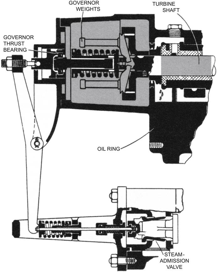
The simplest governors (usually on small, simple turbines) are centrifugal or flyball governors. Opposite weights revolving on a spindle move outward with centrifugal force acting against a spring (with increasing centrifugal force). This changes the position of the steam admission valve with either:
• Operation of a hydraulic system pilot valve that releases fluid to opposite sides of a power piston or one side of a spring-loaded piston that in turn opens or closes the steam valve
Systems for large turbines are complex and involve booster relays to reduce response time. Intercept valves are installed upstream of the intermediate turbine and fulfill the function served by an emergency trip on a simple turbine.
Pressure Governors
Pressure governors generally are used in back-pressure or extraction turbines to maintain constant extraction or exhaust pressure at all loads.
Main Stop Valves
Using a positive spring closing force, the main stop valve (Figure 3A–22) closes rapidly in an emergency. It is standard to provide a built-in pilot valve to equalize pressure between inlet and outlet at startup and an integral steam strainer to protect the turbine from particle damage.
Lubrication System
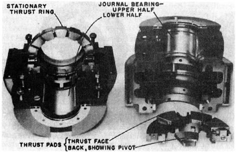
Bearings
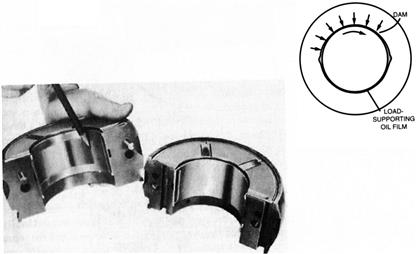
Sleeve (hydrodynamic journal) bearings support the turbine rotor and generator. Jacking oil (oil lift) is provided during startup and shutdown so the weight of the rotor will not cause the shaft to contact the bearing surfaces. The jacking oil also reduces the starting load on the turning gear. This oil lifts the shaft and floats it on an oil film until the shaft speed is high enough to create a hydrodynamic film between the shaft and the babbitt.
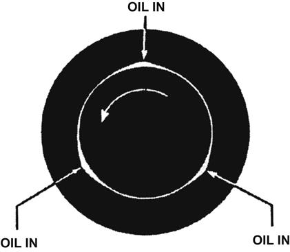
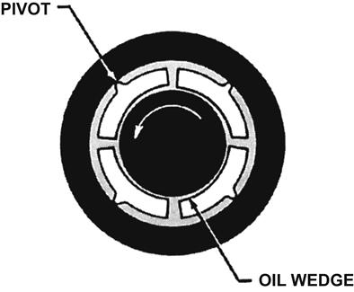
Oil whirl or whip (vibration when the center of journal starts to rotate about the stable position, which is the center of the shaft) is eliminated by use of a pressure pad, tilting pad, or three-lobe designs. (See Figures 3A–23 through 3A–25.)
Thrust bearings absorb the axial thrust that occurs because of the pressure difference across each row of blades. Small turbines use babbitt-faced ends on journal bearings or rolling-element thrust bearings. Larger turbines use tilting-pad or tapered-land bearings. (See Figures 3A–26 and 3A–27.)

Oil
Oil leaving the bearings is about 70°C. The oil system, like the hydraulic system, must be kept free of dirt and small particles.
The factors that affect lubricating oil are:
• Overheating and exposure to air result in oxidation. Fine metal particles from wear accelerate oxidation. This changes the oil composition and viscosity. Sludge may result.
• Leaking turbine and pump seals.
• Water leaks in heat exchangers. Emulsion forms when oil and water mix. Oxidation increases emulsification.
• Rust contamination. Rust particles.
• Catalyze the rate of oil oxidation.
• Block small clearances in the governing system
• Air contamination. Air bubbles cause sponginess in hydraulic controls. They reduce load capacity of oil films. Air accelerates oxidation. It can generate foaming.
Oil, for the turbine model and application in question, needs the correct:
Steam Turbine Governing System
Major Components
How a basic governor works and its major components were covered previously. See Figure 3A–28 for a simple mechanical governor design.
The main functions of a governing system are:
1. To limit the speed rise to specific boundaries when the load is rejected (unit disconnected from the load). This is also covered by the emergency trip.
2. To control the power developed by the steam turbine (by controlling the steam governing valve position).
3. To control the turbine speed during run-up and synchronization.
4. To match the power generated to the power required by the load by responding to frequency changes (when the generator is not connected to the grid, also termed islanding).
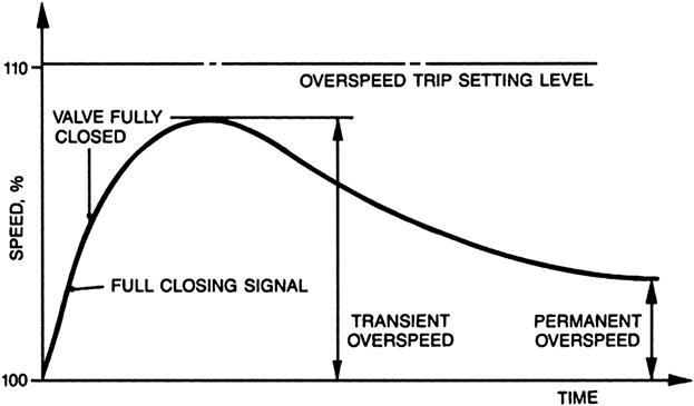
Most grid problems last less than an hour, so the governor needs to keep the unit at running speed, so that resynchronization is possible after the fault condition is over and to ensure continuity of the unit’s power from the generator through the transformer. After a load rejection, there will always be a transient overspeed, due to the response time of the governing valve and the stored energy of the steam in the turbine and rest of the system.
Steam Turbine Operation
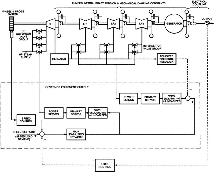
A basic governing system block diagram is shown in Figure 3A–29. Its operation varies with each set of application parameters. In general, however, it:
• Controls the speed versus load curve when the machine is synchronized to the grid
• Determines the position of the governing valve and intermediate valve(s)
Steam Chests and Governing Valves
Numerous standard types of steam chests and governing valves cover a wide range of inlet steam conditions. Steam chests (Figure 3A–30) can be:
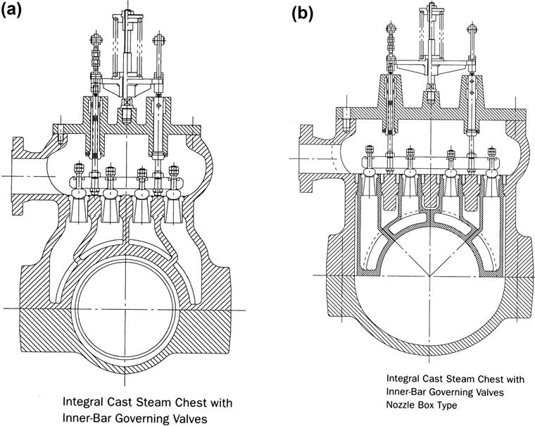
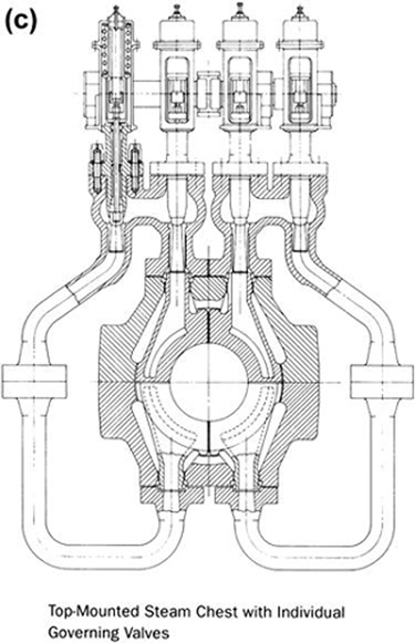
The governing valves have a multivalve arrangement and effective diffusers to minimize inlet energy loss. The valves are operated sequentially to control the inlet steam flow into the turbine with minimum inlet pressure loss. Thus, governing valves enable the turbine to achieve higher efficiency, even at partial loads.
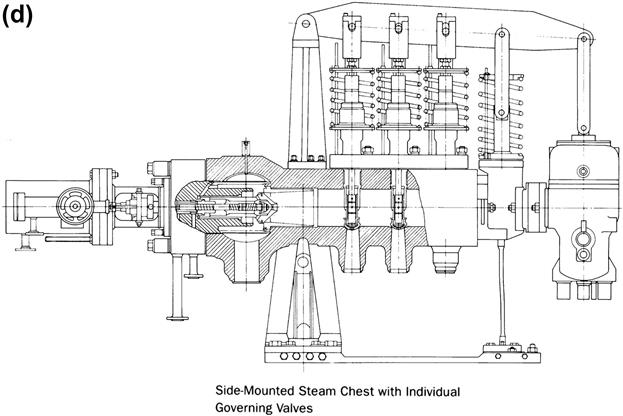
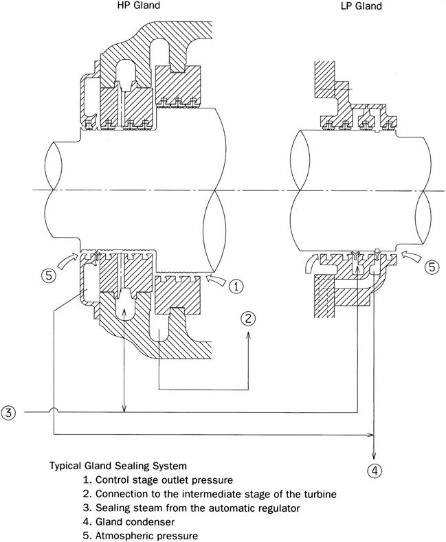
Extraction Control Valves
There are two types of automatic extraction control valves (Figure 3A–31):
• Diffuser type, the standard extraction control valve. Its construction is the same as that of governing valves.
• Grid type, the type of valve commonly used when the extraction pressure is low. It consists of a stationary diaphragm installed in the turbine casing and a rotating port ring actuated by a servo system. The extraction steam flow is controlled by sequential port operation.
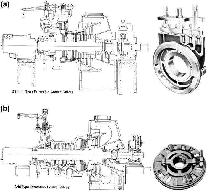
Glands
A typical gland sealing system is shown in Figure 3A–32.
To minimize steam leakage from the turbine gland, spring-backed labyrinth packings are used at both ends of the rotor. The labyrinth packings are divided into several segments to facilitate maintenance. The automatic steam regulator is provided to maintain the seal pressure constant at any turbine load.
Turbine Run-Up
As run-up progresses, the steam flow increases to full load steam flow. At the start of the run-up, 2–3% of full load power is required to overcome mechanical friction and windage losses. A toothed wheel coupled to the main turbine shaft and a speed-sensing device provide speed readings.
For constant steam inlet conditions, power versus steam flow is linear (see Figure 3A–33(a)). It would be desirable to have the steam demand input to the valve vary linearly with load (steam flow). However, Figure 3A–33(b) shows this is not the case. Note that the steam flow varies directly with the boiler pressure (as well as the load).
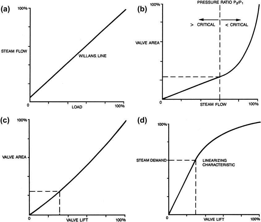
The valve lift, in turn, varies with the valve flow area, see Figure 3A–33(c).
Linearizing circuitry results in the characteristic shown in Figure 3A–33(d).
Turbine Trip (o/s)
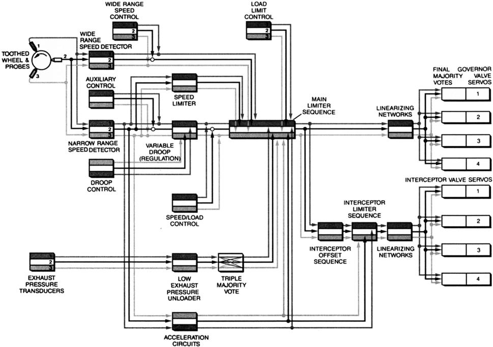
See the discussion in the preceding section. For load rejection (unloading), three channels are used to conduct steam demand signals to each valve controller (see Figure 3A–34). The controller selects an operating demand point based on “majority votes.” The valve position transducer provides feedback on its position to the controller (also see Figure 3A–35).
Hydraulic Fluid
Hydraulic fluid is used to conduct large forces to control the valves. The fluid needs to flow around and through some small clearances. For steam turbines below 500 MW, the hydraulic fluid needs to develop 35 bar or less. For larger turbines, the hydraulic fluid needs to conduct between 70 and 150 bar.
As the fluid pressures are high, a small leak causes a potentially flammable spray. Normal oil ignites on contact with hot pipes. However, phosphate esters are used. They are not flammable and have a long service life. The viscosity of hydraulic fluid needs to be monitored diligently. A change in viscosity may mean slow valve reaction with disastrous pressure build-up or seal failure.
See Figure 3A–36 for a schematic of a hydraulic system. A redundant pumping line also capable of conducting hydraulic fluid adds system reliability.
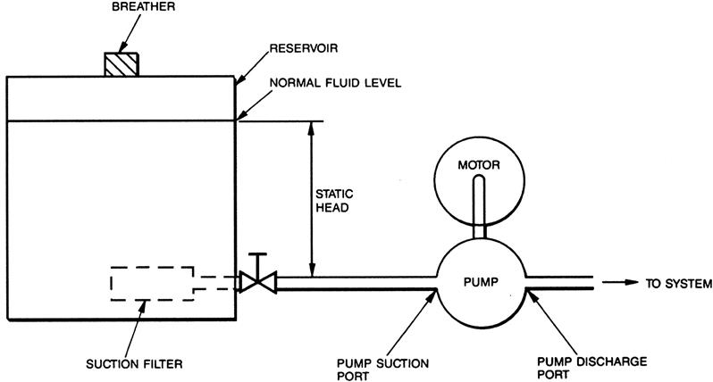
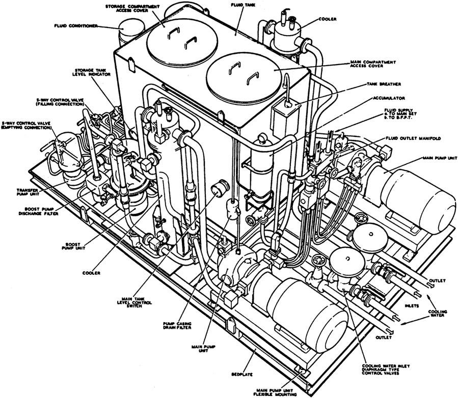
The system pumps are screw or piston type with a coarse inlet filter. A separate centrifugal pump is used to boost fluid volume. The system attempts to maintain 40°C fluid temperature for optimum viscosity. See Figure 3A–37, which depicts a hydraulic system skid.
Tripping Signals
In addition to the main overspeed trip, other relief valves are used in the system to protect individual system components and systems. For instance, reheater valves prevent reheater overpressurization. There may be additional release valves to vent steam under certain conditions, thus avoiding damage to the turbine blades.
These release valves operate hydraulically or pneumatically. In most modern turbine systems, the governor system is electronic and the valves are opened by solenoid valves. They open for:
• Closure of all interceptor steam relays. This includes all turbine trips or load rejection with no trip.
This does not protect against potential steam churning during run-down after a trip or as interceptor valves close after load rejection.
Supercritical Systems: Targeting 700+°C Steam Temperature
Supercritical steam conditions of 250 bar, 600°C HP, and 610°C reheat are now described as state of the art in supercritical steam cycle systems. The prospect of further development towards steam temperatures higher than 700°C has been under active investigation since the early 1990s in Europe, Japan, Russia, and the United States. Discussions with key experts at Siemens15 in Mülheim indicate that while the technology looks feasible, further investigation is needed to demonstrate the economic advantages. Efficiency increases from turbine blade improvements may lower life cycle costs.
Deregulation in the power supply industries around the world does little to advance the cause of supercritical coal fired generating plant systems development, even in countries with a continuing commitment to coal burning.
Countries with limited indigenous fuel resources and a high commitment to environmental protection such as Japan and Denmark, which appear to be dependent on imported coal for the foreseeable future, do have a continuing interest in increasing generating plant efficiency while reducing generating costs.
Australia, Germany, Russia, South Africa, the UK, and to some extent the United States are economically motivated to burn coal from indigenous resources with the highest possible efficiency without sacrificing availability, but the key economic criterion in these days of increasing competition in utility services continues to be the minimization of lifetime operating costs.
Under these conditions the trade-offs between initial design criteria and materials selection against operation and maintenance costs may be conflicting. It is interesting, on the other hand, that China is increasingly interested in installing supercritical coal-fired power plants to gain maximum thermal efficiency.
Current supercritical power plants reach thermal efficiencies of just over 40%, with a few more recent highly supercritical power plants reaching 45%. The leading developers of advanced coal burning power plant technology claim that thermal efficiency as high as 50%, notwithstanding Carnot, is now within reach. But the main competition is from new gas turbine combined-cycle plants which are now aspiring to an overall efficiency of 60%, making a huge difference to generating costs and life cycle costs.
On the other hand, the newest gas turbines that are about to be introduced to the market will exhaust into waste heat recovery steam generators at temperatures above 600°C, necessitating the use of the same high chromium steel alloys such as ASTM-A335 P91 (X10CrMoVNb9-1) in the boiler tube bundles as is used in the more highly supercritical coal-fired conventional generating plants now being built.
While increasing steam temperature is generally agreed to be the most rewarding route to increasing efficiency in coal fired power plant, there are recognized thresholds of investment costs above which the returns are not just diminishing, but increasingly negative.
This has led companies such as Siemens KWU, which is currently assimilating the technology of Westinghouse Electric in the United States, and Parsons in the UK, to concentrate more on the development of advanced steam turbine blading and shaft design than on the use of the newer austenitic steels and nickel-based alloys. Nonetheless, Siemens claims it is able to offer plants designed to work at steam conditions of 300/600/610 and is working towards steam conditions in the order of 300/700/720.
The development of highly supercritical power plants in Germany has been substantially set back since the period of peak interest in 1994/95 with the shelving of the Hessler, Lübeck, and now RWE’s newest Niederaussem power plant unit (250/580/600). But if the EU Energy Charter’s aspirations towards cost transparency ever materialize, operating experience from recently built supercritical coal fired plants like the four big VEAG lignite stations in former eastern Germany—Boxberg, Lippendorf, Schwarze Pumpe (268/547/565), and Jänschwalde—and also the IPP Schkopau, none of which exceeds 40% efficiency by much, will do a good deal to settle the outstanding issues.
Perhaps the most significant reference will be Siemens KWU’s latest supercritical plant contract, the 600 MWe Isogo unit being built for Tokyo Electric Power for operation in 2001, which is rated at 250/600/610, since blades of nickel-based alloys are generally thought to be necessary for reheat temperatures of 610°C and higher. The steam turbines for this will be supplied directly from KWU’s Mülheim works rather than from the local licensee Fuji Electric.
This represents a substantial increase in steam temperature over Chubu Electric’s 700 MWe Kawagoe double reheat systems which run on steam conditions of 311 bar, 566/566/566°C. The first two of these units have been running since June 1989 at efficiencies of 45%, an efficiency gain of 5% over previous conventional plants.
These make strategic use of 12% chrome cast steel in the Toshiba turbines and blades and 9% chrome in the pipework.
This was the first use of such alloys in Japan since the standard single reheat steam conditions of 242 bar, 538/566°C were established for large fossil fueled steam turbines. Since the Kawagoe units demand the high levels of availability that has been essential for large fossil fired middle load power plants in recent years, operating experience from this station is of inestimable importance to advanced supercritical system development.
International Development Programs
By 1995 research and development anticipating 50% net plant efficiency within five to seven years was proceeding worldwide with the Brite Euram and COST in the European Community, the VKR Hessler and Preussenelektra Lübeck projects in Germany, the ELSAM “Convoy” double reheat power projects in Denmark, the KEMA work in the Netherlands, EPRI 1403–50 in the United States, and CRIEPI in Japan.
Much of the attention under these programs was directed at the metallurgical problems of the steam generators and the tendency for thinning of the superheater tubes in service using the ferritic/martensitic steels in common use. Some parties believe that in practice the tube thinning will not happen, and the new plants now beginning to operate in Germany, Japan, and Denmark will give valuable insight and design validation for future projects.
The Schwarze Pumpe 2 × 800 MWe power plant recently commissioned near Dresden in the Lausitz lignite mining area is a good example. These are thought to be largest lignite boilers ever built, with physical dimensions of 161 m in height, 24 m × 24 m in cross section. They are once-through, single pass boilers designed by EVT as 900 MWe units but with a high process steam output of up to 800 t/h to various process plants in the region. Then plants have steam parameters of 268 bar/547°C/565°C for the maximum steam generating capacity of 2420 t/h.
This is said to be the first time that P91 has been used for a power plant steam generator of this size. Used for the live steam and hot reheat piping, this material was selected as having higher creep rupture stress than the X20CrMoV121 normally used, which leads to lower tube wall thicknesses and hence reduction in thermal stresses. The weight reduction in turn reduces stress levels at the boiler connections and at the turbine connections as well as on the structural steelwork.
A seven stage regenerative feed heating system driven by a turbine driven feed pump delivers feedwater at a final temperature of 270°C. The supercritical steam output supplies a single reheat turbine system in sliding pressure mode with main steam at 638 kg/s, 253 bar, 544°C, and reheat at 52 bar, 562°C.
Feedwater temperature is becoming an increasingly critical parameter in recent years with the added emphasis on emissions control. There are economic benefits in raising steam pressure to 300 bar since, because of the lower thermal energy transfer required in the evaporator, the heat exchange area required is reduced with a corresponding saving in costly high chromium alloys.
On the other hand, the maximum furnace temperatures have to be retained, even to the point of possibly removing the economizer, but this will then not cater for reheat inlet temperatures above 310°C because the limitations on maximum SCR temperature will be exceeded.
Since with the high process heat output at Schwarze Pumpe a fuel utilization efficiency of some 55% is claimed, it may be considered that cogeneration of heat and steam could be a more economic approach to beating Carnot, but there are not that many instances of adequately large heat loads existing close to the mine mouth sites adjacent to the coal resources.
With such constraints and the economic limitations inherent in using P91, P92, austenitic steel alloys, and nickel-based alloys for which good creep and manufacturability data are only available from the nuclear industry, Siemens have placed increasing reliance on steam turbine design advances in their quest to break the magic 50% thermal efficiency barrier.
Boiler Design
Siemens has been promoting the once-through boiler concept since they acquired the Mark Benson patent in the 1920s because it brought the capacity for high-pressure boiler potential into the field of power generation for the first time. They claim responsibility for the spiral configuration of the evaporator tubes, and they have since further developed this vertical tube design with a view to reducing investment costs while at the same time introducing boilers operating at supercritical pressures in which the drum type boiler has been the dominant design.
By using rifled tubes with high heat transfer capacities, they were able to reduce mass velocity in the tubes as much as 2500 kg/m2s to less than 1200 kg/m2s. The popular reference for this design is the 550 MW Staudinger Unit 5. This operates at 260 bar, 545/562°C, still using low-cost martensitic steels for the final stages of the HP and reheater heating surfaces.
Bent Blades
Fullly three-dimensional, variable reaction blading with compound lean, a Siemens development designated 3DV—the already well publicized curved blades—is the main ingredient in optimizing HP and IP turbine efficiencies. Relevant here is a dispute among turbine engineers that goes back more than 100 years over the choice of stage reaction, i.e., the split of pressure drop and velocity increase between stationary blades and moving blades. Defined more scientifically, stage reaction is the ratio of the enthalpy drop in the rotating row to the enthalpy drop of a whole stage.
A reaction turbine is characterized by a stage reaction of 50%, and the enthalpy drop is equally divided between across stator and rotor rows. The symmetry in enthalpy drop entails a symmetry in flow relative to stator and rotor flows and allows the same profile to be used for both blade rows. In this case, flow velocities and flow directions along the blade path are moderate and profile and secondary losses are quite low. Since half of the enthalpy drop occurs in the rotor row, the pressure differential across the rotor blades is rather high and exerts a large axial thrust on the rotor.
In order to compensate for this axial thrust, a dummy balance piston is required in single flow designs. The leakage flow across this dummy piston reduces the turbine cylinder efficiency.
In impulse turbines with zero stage reaction, the total stage enthalpy is converted into kinetic energy in the stator row, while the rotor row merely deflects the steam without further acceleration. In this case different profiles must be used for stator and rotor blades because their flows are asymmetrical.
Flow velocities and flow deflection along the blade path are significantly larger than the equivalent reaction stages, incurring higher profile and secondary losses. Since the pressure differential across the rotor is much less than that for reaction turbines, a much smaller dummy balance piston with lower losses can be used.
Three-dimensional blades have the potential to exploit the best of both worlds, and Siemens maintain that by the use of computer controlled five axis milling machines, any three-dimensional blade that the design engineer can invent can now be manufactured.
For the first stages of HP and IP turbines, a special three-dimensional blade with compound lean has been developed by Siemens.
In these stages, the secondary losses are significant due to the low volume flow rates and short blade lengths. Compound lean and twist both serve to reduce the secondary losses at the root and the tip of blade. The reaction of each stage is set individually and may vary between 10 and 60%.
Extensive measurements were performed on a four-stage test turbine to confirm efficiency improvements of up to 2%—a major gain—compared with conventional cylindrical blading.
Another feature of the Siemens KWU supercritical IP turbine is the vortex cooling principle. For rotor stress reduction in the steam admission zone, the rotor is built without an axial through bore.
There is a double “T” root configuration for the two first stages with tilted first row stationary blades mounted on a heat shield ring with a cooling passage beneath the root. Cooling steam flows through tangential bores to form a vortex that cools the rotor since the steam temperature is reduced by its expansion to a high level of kinetic energy.
The rotor surface temperature distribution shows a temperature reduction of up to 16°C at the critical rotor section, which is enough to greatly improve the stress characteristics of the design.
Economic Advantage
Every 1% of efficiency increase gained by the use of more highly supercritical steam conditions is reckoned to increase the output of a 660 MW turbine system in Germany by some 3 MW at normal input conditions.
The higher efficiency saves about 5600 t of coal per year, which in turn saves about 12,500 t of CO2 emissions. On top of this, life cycle costs in Germany are reduced by about $6 million.
Case Study 3A-1: Advanced Design of Mitsubishi Large Steam Turbines16
Mitsubishi has developed modern high temperature steam turbines based on advanced technologies, including advanced steam path design through fully 3-D computational fluid dynamic (CFD) analysis methodologies, high loading reaction blades, high efficiency seals due to active clearance control, rotor cooling structure, enhanced LP section, and state-of-the-art material technologies, which are now market ready. The LP enhancement includes the world longest LP last blades such as 3600 rpm 40 inch and 3000 rpm 48 inch steel blade.
The main specifications and features for recently designed steam turbines of different power output ranges are shown in Table 3A–2. The 600 MW high temperature tandem-compound turbine design (A) of Hirono No. 5 unit, Tokyo Electric Power Co., is comprised of one combined high/intermediate pressure (HP/IP) turbine and one double flow low-pressure (LP) turbine with 3000 rpm 48 inch steel LP last stage blades. The 700 MW (B) Kobe # 1 unit started commercial operation in 2002 and it is composed of one combined HP/IP casing and two LP casings with 3600 rpm 40 inch last stage blade. The 840 MW tandem-compound four casings design (C) of Thailand Ratchaburi units No. 1/No. 2 started commercial operation in 2000. This machine is composed of one double flow HP, IP turbine and two double flow LP turbines.
TABLE 3A–2
Main Specifications and Features of Recently Designed Steam Turbines for Conventional Plants [3-5]
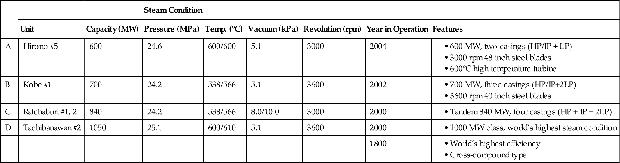
The 1050 MW Tachibana-wan power plant unit 2 (D), Electric Power Development Co., entered commercial operation in December 2000. This turbine is a typical cross-compound machine designed with the industry highest steam temperatures and achieving the highest gross efficiency in the world.
As for 50 Hz application, the optimum LP last blade design for 50 Hz will be selected in accordance with the required power output and the available power train combination for the 50 Hz application. Table 3A–4 presents two examples of the main features of modern MHI steam turbines for combined cycle application.
TABLE 3A–3
Example of Recent MHI Steam Turbine Designs for Combined Cycle Applications [3-5]
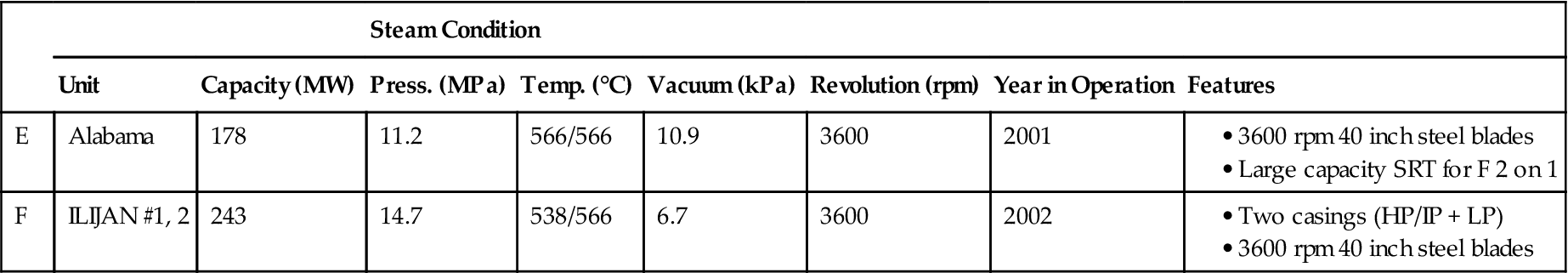
TABLE 3A–4
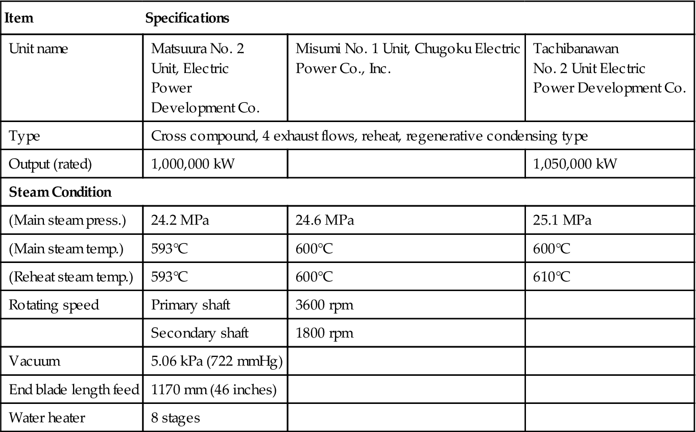
Major Specifications of 600°C Class 1000 MW Steam Turbines [3-5]
| Item | Specifications | ||
| Unit name | Matsuura No. 2 Unit, Electric Power Development Co. |
Misumi No. 1 Unit, Chugoku Electric Power Co., Inc. |
Tachibanawan No. 2 Unit Electric Power Development Co. |
| Type | Cross compound, 4 exhaust flows, reheat, regenerative condensing type | ||
| Output (rated) | 1,000,000 kW | 1,050,000 kW | |
| Steam Condition | |||
| (Main steam press.) | 24.2 MPa | 24.6 MPa | 25.1 MPa |
| (Main steam temp.) | 593°C | 600°C | 600°C |
| (Reheat steam temp.) | 593°C | 600°C | 610°C |
| Rotating speed | Primary shaft | 3600 rpm | |
| Secondary shaft | 1800 rpm | ||
| Vacuum | 5.06 kPa (722 mmHg) | ||
| End blade length feed | 1170 mm (46 inches) | ||
| Water heater | 8 stages | ||
Units E and F in Table 3A–3 are typical steam turbine frames for 2 on 1 combined cycles. The E unit is designed with single casing (HP/IP and LP combined type: single reheat turbine). Both E and F units apply 3600 rpm 40 inch steel LP last blades.
The main design features of MHI large capacity steam turbines are summarized as follows:
• Compact HP/IP combined turbine with high efficiency reaction blades
This section describes these design features and operating experience of large steam turbines recently designed for fossil-fuel and combined-cycle power plants.
Product Line of MHI’s New Advanced LP Last Stage Blade
A new standard series of these LP last stage blades was completed for 50 Hz and 60 Hz unit application including 3600 rpm 45 inch titanium blade, 3000 rpm 48 inch steel blade, and 1500/1800 rpm 54 inch steel blade, which have the largest exhaust annulus area among the same class blades in the industry.
High Temperature Design
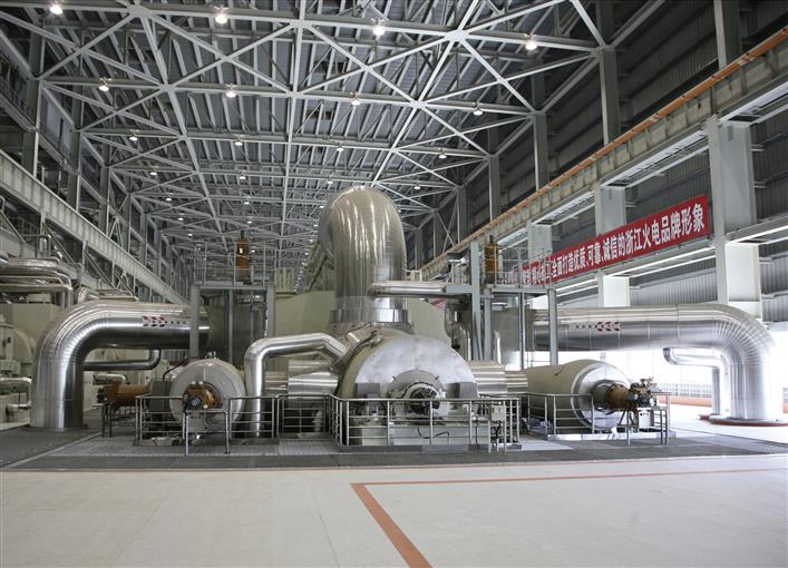
Tachibana-wan No. 2 unit in Shikoku, Japan, for Electric Power Development Co. (EPDC) is a 1000 MW cross-compound plant with maximum temperature of 600/610°C (see Table 3A–4). The HP and IP turbines are positioned on the high-speed shaft (3600 rpm) and two double-exhaust LP turbines on the low-speed shaft (1800 rpm). This unit has been operating successfully since December 2000 and the acceptance test demonstrated that the gross efficiency figures achieved a new benchmark (about 49%) for 1000 MW class steam turbine.
Ferritic heat-resistant steel materials are widely used for 600°C class high temperature turbines, such as new 12 Cr forged, 12 Cr cast, and 9 Cr forged steels. In high temperature rotating blades, austenitic refractory alloys are used, while 12 Cr forged steel having sufficient creep rupture strength for operation at 600°C class temperatures is used as the rotor material. In the journal and thrust collar sections of the 12 Cr rotor, a low Cr overlay material is used in order to reduce wear of bearing materials. As for the materials for stationary parts, 12 Cr cast steel (MJC-12), which has excellent creep rupture strength, is used in the nozzle chamber and inner casing. A 9 Cr forged steel is used in the main stop valve, HP turbine inlet, governing valve, and connection piping between the valves and casing (see Table 3A–5).
TABLE 3A–5
Materials for HP, IP Turbines [3-5]
| EPDC Matsuura No. 2 1000 MW (538/566°C) | Cyuubu Elec. Co., Inc. Heklmar No. 3 700 MW (538/593°C) | EPDC Tachbana-wan No. 2 1050 MW (600/610°C) | |
| HP Turbine | |||
| Rotor | Cr MoV forging | CrMoV forging | New 12 Cr forging |
| Inner Casing | 2¼ CrMoV cast steel | 2¼ CrMoV cast Steel | 12 Cr cast steel |
| MSV/CV | 2¼ CrMoV forging | 2¼ CrMoV forging | 9 Cr forging |
| Main Steam Inlet | 2¼ CrMoV forging | 2¼ CrMoV forging | 9 Cr forging |
| Pipe | |||
| IP Turbine | |||
| Rotor | MoV forging | 1 C forging | New 12 Cr forging |
| Inner Casing | 2¼ CrMoV cast steel | 12 Cr cast steel | 12 Cr cast steel |
| RSS/VC | 2¼ CrMoV forging | 9 Cr forging | 9 Cr forging |
| Reheat Steam Inlet | 2¼ CrMoV forging | 9 Cr forging | 9 Cr forging |
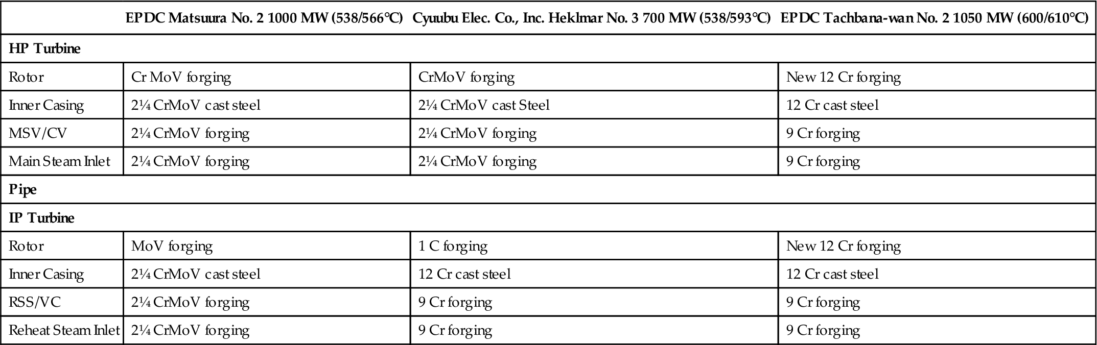
MHI Development Material Rotor: TMK-1,2, Casing MJC-12.
US Development Material Super 9 Cr.
The upper limit for steam temperatures initially applied for new 12 Cr steel rotors designated TMK-1/2 was 600°C class. However, this limit has been raised after development of advanced 12 Cr (with Co) steel for recent projects on Mitsubishi advanced steam turbines of large capacity. This material is superior to new 12 Cr or 9 Cr steel in terms of high temperature strength.
Ultra Supercritical Steam (USC ST) Turbines
Super-critical steam has been around since the 1950s. The countries that took advantage of this technology included countries like China, which are relatively poor in oil and gas resources. Even with the onset of fracking technology, the increase in energy demands globally are such that coal will continue in its use as a fuel for the forseeable future. The development of renewables continues, but that curve is not as steep as environmentalists would have it. Also new gas resources discovered by fracking still will not totally fill the energy need, even in the USA with its own domestic reserves of conventional oil and gas (supplemented by synthetic crude imports from Canada and oil imports from the rest of the world). Since coal is a reality that will not go away, research work, with organizations such as the US DOE, continue to develop metallurgy that handles USCS well. Several plants around the world (a case study follows here) prove that this is attainable.
Metallurgists, however, push still harder to attain steam temperatures of over 750°C. A brief extract of US DOE work in this vein follows the case study.
Consider also that GT systems operators, especially in power generation, are becoming more astute with cogeneration applications, the use of alternative fuels, and CHP systems. Also, as transmission technology improves, plant operators are more adept at integrating GT systems with ST systems, as well as renewable energies (better handled now by smart grid technology).
| Item | Not Exceed Limit | Requirement |
| Engine oil tank | Flight termination | Check oil level. Replenish as necessary. Record amount taken |
| Cowls | Transit | Check the pod cowls for damage and external evidence of fuel and oil leaks |
| Caps and access panels | Transit | Check secure |
| Engine intake | Transit | Check clear. Free from damage and loose objects |
| Turbine and exhaust collector | Transit | Visually inspect for signs of damage and metal deposits |
| Engine intake | 25 hours | Visually inspect front of engine through air intake for signs of damage paying particular attention to intake guide vanes and leading stage rotor blades |
| Turbine and exhaust collector | 25 hours | Visually inspect L.P.2 turbine blades, nozzle guide vanes and mixer unit for cracking and damage by viewing from rear using a strong spotlight |
| Fuel filter | 125 hours | Drain sample and check for water contamination |
| Magnetic chip detector | 200 hours | Remove and inspect |
| Igniter plugs | 200 hours | Audibly check operation |
| Oil pressure filter | 600 hours | Check and clean/renew filter element |
| Fuel filter | 800 hours | Remove filter element, check and renew |
Case Study 3A-2: One OEM's Supercritical ST Product Range with Specific Reference to the 800 MW Trianel Power Project in Lünen17
This case presents Siemens products and solutions for ultra supercritical steam power plants and their application in the 800 MW Trianel Power project in Lünen. Several German and European municipal utility companies hold a share in Trianel Kohlekraftwerk Lünen GmbH & Co. KG. Advanced steam parameters (280 bar/600°C/610°C), a net efficiency above 45% (LHV basis, hard coal), and specific CO2 emissions well below 800 g/kWh are characteristic features of this project.
The Lünen power plant will meet the most stringent environmental protection requirements of the German authorities and will have among the lowest environmental emissions of any coal-fired power plant in Germany.
The flue gas cleaning system includes equipment for removing nitrogen oxides (SCR reactor), particulates (electrostatic precipitators) and sulfurous components (flue gas desulfurization unit). Typical emissions limits are as follows:
Completely enclosed conveyor belts will supply the fuel from the ship unloading station to the closed coal silos and next to the coal bunkers of the steam generator. Such a complex coal-handling system avoids emissions of respirable dust to a large extent. Clean flue gas is supplied to the natural-draft wet cooling tower. Large amounts of moisturized air in the cooling tower ensure that the emissions are highly diluted before they are rejected to the environment.
Noise emissions measured above background levels at a distance of 0.5 km from the power plant site will be no greater than 60 dB(A) during the day and 45 db(A) during the night, whereby the proportionate noise rating level generated exclusively by the power plant has to be 10 dB (A) lower at these immission points.
Due to the high efficiency of the overall plant, specific CO2 emissions are well below 800 g/kWh. Technologies for removing CO2 from the exhaust gas of coal-fired steam power plants are still under development. Several small-scale postcombustion CO2 capture pilot plants based on different CO2 solvents are in operation (e.g., the Castor project in Esbjerg) or have been announced. Significant efficiency penalties, tougher requirements for flue gas desulfurization, and solvent degradation in oxygen-rich exhaust gases are some of the difficulties associated with postcombustion CO2 capture that need to be addressed (see Table 3A–6).
TABLE 3A–6
| Gross power output | 813 MW (rated output; 50 Hz); single unit |
| Net efficiency (LHV basic) | ∼45.6% (@ design point) |
| Steam generator | Tower-type once-through boiler with vertical evaporator tubing |
| Gas cleaning | Selective catalytic reactor (DeNOx), electrostatic precipitators (particulate matters), and wet limestone flue gas desulfurization (SOx) |
| Steam parameters | 280 bar/600°C/610°C steam parameters at boiler output |
| Steam turbine | SST5-6000 with single reheat and two double-flow LP turbines (4×12.5 m2 exhaust annular area) |
| Generator | SGen5-3000 W, water/hydrogen-cooled |
| Feedwater preheating | 9-stages: 3 high-pressure FWPH (header-type) with one external desuperheater, 5 low-pressure FWPH (plate-type); feedwater heaters A1 and A2 are located in the condenser neck as a duplex heater |
| Final feedwater temperature | 308°C |
| Feedwater pump concept | 2 × 50% electric motor-driven feedwater pumps |
| Condenser | Dual-pressure serial condenser operating at 30 and 45 mbar respectively |
| Flue gas discharge | Via the natural-draft wet cooling tower |
| Distributed control system | SPPA-T3000 power plant automation system |
Turbine-Generator
For the 50 Hz market, Siemens offers full speed tandem compound turbo-sets for steam power plants (SPP) with ultra supercritical steam parameters in the gross power output range of 600–1200 MW per unit. The steam turbine set SST5-6000 used in Lünen is a four-casing design with separate HP, IP, and two LP turbines (Figure 3A–38).
High parameter values for the main steam (270 bar, ∼600°C) and reheat steam (60 bar, ∼610°C) at the turbine inlet pose special requirements on both the design and the materials. For example, the HP cylinder is designed as a barrel-type turbine and has an inner casing. Ultra supercritical steam conditions usually require the use of thick-walled components. The rate of heat transfer into these components is often the limiting factor for the duration of the startup process. In order to remove this restriction, a special feature has been developed for HP turbine modules: An internal bypass cooling system that allows for a more flexible operation (startup/load changes). In a nutshell, a small amount of cooling steam passes through radial bores into the small annulus between the inner and outer HP casing (Figure 3A–39).
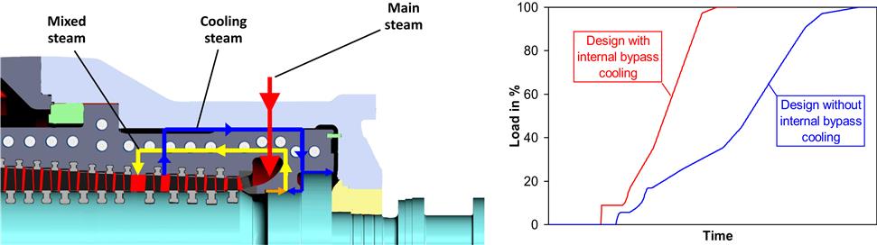
This approach effectively protects the inner surface of the outer casing (which would be exposed to main steam temperature without the internal bypass cooling). As a consequence it was possible to reduce the wall-thickness of the outer casing and thus enable faster heat-up of the casing. An improved starting performance is the main customer benefit of this innovative concept. Components exposed to high temperatures such as the HP inlet barrel as well as HP/IP rotors and inner casings are made of 9–12% CrMoV steel. Siemens advanced 3DV™ technology (three-dimensional design with variable reaction levels) for HP/IP blades is used in Lünens’ steam turbine generator set. With 3DV™ blades the stage reaction and stage loading for each row is optimized to gain highest HP and IP efficiencies. Stage reaction describes the split of pressure drop and velocity increase between stationary and moving blades, and is defined by the ratio of the enthalpy drop through the moving blade row to the enthalpy drop through the whole stage. Both low-pressure turbines are double-flow designs. Free-standing 1150 mm steel last stage blades (LSB) provide an annular area of 12.5 m2 per flow.
US DOE Work on USC ST Materials18
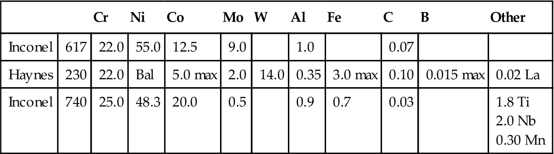
As part of a larger collaborative effort, the Albany Research Center (ARC) is examining the steam-side oxidation behavior for ultrasupercritical (USC) steam turbine applications. Initial tests are being done on six alloys identified as candidates for USC steam boiler applications: ferritic alloy SAVE12, austenitic alloy Super 304H, the high Cr-high Ni alloy HR6W, and the nickel-base superalloys Inconel 617, Haynes 230, and Inconel 740. Each of these alloys has very high strength for its alloy type.
The Advanced Research (AR) program has two efforts in ultra-supercritical (USC) steam—one on USC boilers and one on USC turbines. The overall steam temperature and pressure goal is 760°C (1400°F) and 38.5 MPa (5586 psi) by 2020. There are intermediate goals for demonstrating the use of materials with steam temperatures of 650°C (1202°F) by 2010 and 760°C (1400°F) by 2015.
The Albany Research Center (ARC) is taking part in the steamside oxidation research in the USC turbine effort. A major part of the USC turbine effort is the selection or development of candidate alloys suitable for use in the USC turbine. Until candidate alloys are selected, initial tests at ARC will be done using the six candidates from the USC boiler project that have already been identified. These are ferritic alloy SAVE12, austenitic alloy Super 304H, the high Cr-high Ni alloy HR6W, and the nickel-base superalloys Inconel 617, Haynes 230, and Inconel 740. Each of these alloys has very high strength for its alloy type. Three types of oxidation experiments are planned: cyclic oxidation in air plus steam at atmospheric pressure, thermogravimetric analysis (TGA) in steam at atmospheric pressure, and exposure tests in supercritical steam up to 650°C (1202°F) and 34.5 MPa (5000 psi).
Alloys
Initial oxidation experiments are planned for the six alloys selected as candidates for the USC boiler effort. The primary aim of these initial experiments is to ensure that the three types of experiments are working properly and will be ready when the USC turbine alloys are selected. However, these results should also benefit the USC boiler research and overall USC goals. The six alloys are ferritic alloy SAVE12, austenitic alloy Super 304H, the high Cr-high Ni alloy HR6W, and the nickel-base superalloys Inconel 617, Haynes 230, and Inconel 740.
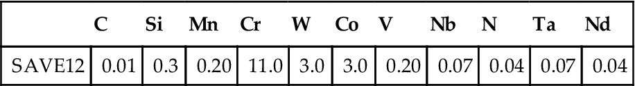
One efficiency, as used here, is based on higher heating value (HHV), or gross calorific value. Ferritic stainless steels with 9–12% Cr are currently used with steam temperatures of about 600°C (1112°F). Most estimates of the upper temperature limit are about 650°C (1202°F), with high temperature strength being the limiting factor. Two very similar alloys, SAVE12 (Sumitomo Metal Industries) and NF12 (Nippon Steel Co.), have 105 h creep rupture strengths of 180 MPa at 600°C (1112°F). The composition of SAVE12 is given in Table 3A–7.
TABLE 3A–7
Composition of Ferritic Stainless Steel SAVE12
| C | Si | Mn | Cr | W | Co | V | Nb | N | Ta | Nd | |
| SAVE12 | 0.01 | 0.3 | 0.20 | 11.0 | 3.0 | 3.0 | 0.20 | 0.07 | 0.04 | 0.07 | 0.04 |
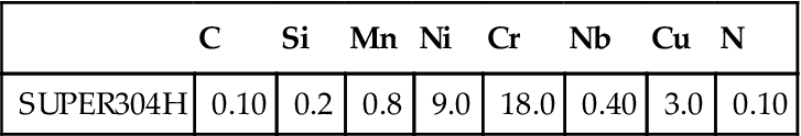
Austenitic stainless steels maintain their strength at higher temperatures than ferritic alloys, and so were used in the early USC plants in the 1950s and 1960s. However, severe thermal fatigue problems prevented their continued use at the original design temperatures and pressures. Because thermal fatigue becomes more of an issue in thicker component sections, austenitic alloys may still find use in certain thinner components. One alloy was selected as a candidate USC boiler alloy: SUPER304H. Its composition is shown in Table 3A–8. It has a 105 h creep rupture strength of 168 MPa at 600°C (1112°F). It is currently used in boiler sections of advanced Japanese USC power stations (including Matsuura 2, Haramachi 2, Misumi 1, Tsuruga 2, Tachibanawan 2, and Isogo 1) with steam parameters as high as 28.0 MPa/605°C/613°C (Isogo 1).
TABLE 3A–8
Composition of Austenitic Stainless Steel SUPER304H
| C | Si | Mn | Ni | Cr | Nb | Cu | N | |
| SUPER304H | 0.10 | 0.2 | 0.8 | 9.0 | 18.0 | 0.40 | 3.0 | 0.10 |
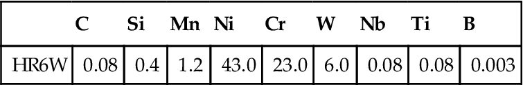
The high Cr/high Ni alloy HR6W is also a candidate USC boiler alloy. Its composition is shown in Table 3A–9.
TABLE 3A–9
Composition of High Cr-high Ni Alloy HR6W
| C | Si | Mn | Ni | Cr | W | Nb | Ti | B | |
| HR6W | 0.08 | 0.4 | 1.2 | 43.0 | 23.0 | 6.0 | 0.08 | 0.08 | 0.003 |
Three nickel-base superalloys are candidates: Inconel 617, Haynes 230, and Inconel 740. Extensive prior testing for gas turbine applications should reduce their development time and cost as compared to new superalloys. Their compositions are shown in Table 3A–10.