
Microwelding methods in medical components and devices
Abstract:
Implantable cardiac rhythm devices, cochlear implants, and neurostimulators are some of the most complex medical devices. Not only do they comprise all of the materials of electronic assemblies, they require the biocompatibility and extreme reliability required for human use. The selection of the outer-case materials is typically driven by the ability to provide a hermetically sealed enclosure, and long-term corrosion resistance. Typical materials now in use include 316L stainless steels, MP35N, titanium, niobium, and alloys of platinum–iridium. Microjoining for these materials and applications includes the welding of pacing lead coils to terminal pins via resistance and laser-spot welding, laser-seam welding thin titanium housings, and spot welding of thin electrode rings to interconnect wires by various welding techniques. This chapter will review key aspects of material choices and the typical joining processes for medical devices.
3.1 Introduction
The ageing of America and many of the industrialized countries has placed a burden on the healthcare industry. A key area within healthcare today is the burgeoning field of implantable medical devices and components. These devices include the now well-known pacemakers, but also include implantable defibrillators, heart failure cardiac care, neurostimulators, pumps, drug delivery, arterial stents, and other smart electronics or components.
All of these devices contain a wide variety of materials and joining processes. Due to the implant size and their intended purpose, the raw materials and assembly processes must be of the highest quality and reliability. Medical devices can be some of the most demanding applications due to the requirements for biocompatibility. The degree of compatibility required is driven by the type of application and the time requirement for interaction with the human body. These applications are typically divided into three classes per FDA specification, with class I being minimal risk, such as a monitoring device or external pump, to a Class III device such as a permanently implanted arterial stent or pacemaker.1 An additional requirement for medical devices is the need for extremely high reliability, to avoid any adverse risk to a patient. The combination of these two requirements, biocompatibility and reliability, makes medical devices a challenge to design and manufacture.
Some medical devices seem simple, yet have high degrees of complexity to predict final form and function. An example of this type of device is a bare metal stent. They are simple only in the sense that they are manufactured (laser cut) from a single tube of specialty metal, typically a cobalt bearing alloy, or other special alloys of nickel–titanium. These alloys can be fabricated with an optimal surface finish for the adhesion of supplemental polymer coatings that are doped with steroid drugs to control the normal inflammation response of the body and to control chronic restinosis.
Larger, more complex medical devices would include prostheses, including knee and hip replacements, polymer finger joints, and new vertebral disc implants. Many of these types of implants use multiple materials and forms of materials to enhance the human body’s response to the material. The hip implant is an excellent example. The ball of the acetabular insert is covered in small cobalt alloy spheres, which yield a high surface area for bonding into the pelvic bone. An insert of high molecular weight polyethylene is used in the acetabular cup to provide a lubricious smooth surface for the mating ball socket of the hip implant. In this example the cobalt spheres are joined to the main body of the implant by sintering, while the high molecular weight polyethylene cup is ultrasonically staked through an opening in the metal housing.2
Implantable cardiac rhythm devices, cochlear implants, and neurostimulator devices are some of the most complex medical devices. Not only do they comprise all of the materials of electronic assemblies, they require the biocompatibility and extreme reliability required for human use. So the selection of the outer-case materials is typically driven by the ability to provide a hermetically sealed enclosure, and long-term corrosion resistance. Typical materials now in use include 316L stainless steels, MP35N, titanium, niobium, and alloys of platinum–iridium. Microjoining in this application includes the welding of pacing lead coils to terminal pins via resistance and laser-spot welding, laser-seam welding thin titanium housings, and spot welding of thin electrode rings to interconnect wires.
This chapter will review key aspects of material choices and the typical joining processes for medical devices.
3.2 Materials challenges
Implantable devices are approved for use by the FDA according to a device’s ability to provide therapeutic value to the patient. Since the full device is approved in the process, individual materials alone are not approved for use. Therefore, most designs leverage off past proven designs where a material has been shown to perform well within a system.
Materials that have passed device-level approvals for a wide variety of implants are shown in Table 3.1. These materials all have the following key characteristics:
Table 3.1
| Material | Application | Joining methods |
| Platinum | Wires, coils, electrodes, pins | Resistance, laser, ultrasonic |
| Pt/iridium | Wires, coils, electrodes | Resistance, laser, ultrasonic |
| Tantalum | Wire, coils | Resistance, laser, brazing |
| Titanium | Wires, coils, terminal pins, pulse generator (PG) cases | Resistance, laser, brazing |
| MP35N | Wires, coils, terminal pins PG cases, battery cases | Resistance, laser |
| Kovar | Standoffs, interconnect pads | Resistance, laser, brazing |
| 316 SS | Wires, terminal, battery cases, capacitor cases | Resistance, laser, brazing |
| Lead free solders | Surface mount bumps, general soldering | Brazing, soldering, ultrasonics |
| Polyurethane | Tubings, seals | Laser, adhesive |
| Silicone | Tubings, seals, adhesives | Adhesives |
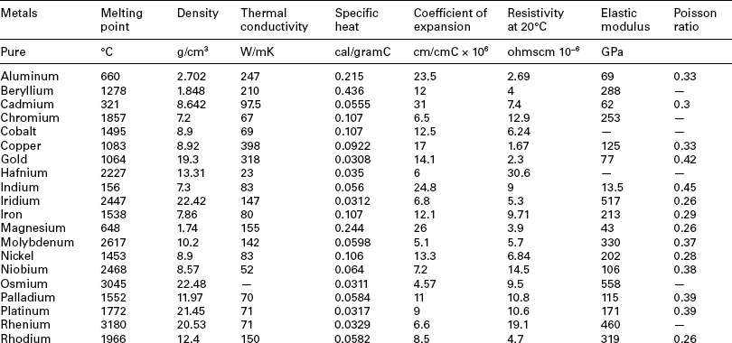
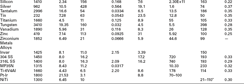
These materials are generally chosen at the beginning of design efforts due to their corrosion, electrical, and biocompatibility performance. However, that does not mean they can be joined in any combination using any methods. Further, while macroscopic size assemblies can often be joined, small-scale microscopic assemblies require more effort to maintain a tight joint during joining processes. Figures 3.1 and 3.2 highlight many common medical grade materials and their ability to be joined by various welding technologies. The tables assume a full fusion joint is developed between the parent materials. Many solid-state welds can be formed from combinations that under full fusion would develop unusable intermetallics. Similarly, the speed of cooling in some small-scale laser welds allows the weld pool to freeze before bad microstructure can develop, allowing combinations of materials not allowed in the figure. Typical material properties for many common metals and alloys are shown in Table 3.2.3,4

3.1 Weldability matrix for plastics. Note: this chart depicts compatibility as a complete mixing of materials resulting in a homogeneous bond. Other combinations of materials may be used to create mechanical or partial bonds. (courtesy EWI)
3.2 Weldability matrix for metals. (A and B refer to electrode material selections for resistance welding. Contact Unitek Miyachi Corporation for electrode materials.) (courtesy Unitek Miyachi Corporation)
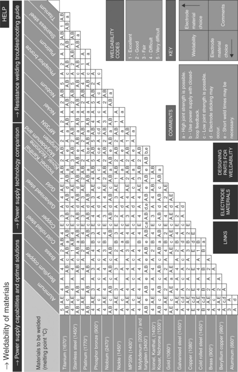
Materials to be joined will be affected by all of the significant variables (process parameters, welding consumables, etc.). For example, the ductility of titanium welds can be greatly reduced through picking up interstitial elements, such as oxygen nitrogen and hydrogen, if shielding is inadequate during welding. A study of laser welding of titanium indicated that addition of oxygen in pure argon shielding gas (as in the case of shielding deficiency) caused further changes in weld microstructure (Fig. 3.3) and fracture morphology (Fig. 3.4).5 Addition of oxygen in the shielding gas increased the amount of acicular and platelet alpha compared to equiaxed alpha in the base metal. As the oxygen content continued to increase (above 1.5–2.0%), weld microstructure was dominated by the acicular and platelet alpha. At very high oxygen content, the alpha platelets formed in colonies, giving a basketweave appearance (Fig. 3.3f). Accordingly, fracture surfaces during tensile testing changed from ductile manner with classical dimple morphology for the base metal to brittle appearance for welds made with oxygen addition. When the oxygen content was high (Fig. 3.4f), the weld fractures as intergranular along colony boundaries or cleavage across colonies, which indicates a complete brittle fracture.
3.3 Micrographs of (a) base metal and (b–f) laser welds made with various oxygen contents in argon shielding gas: (b) 0%; (c) 0.5%; (d) 1.5%; (e) 3.0%; (f) 10.0%.5
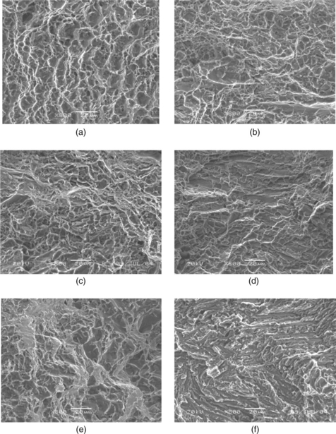
3.4 Fracture surfaces of (a) base metal and (b–f) laser welds made with various oxygen contents in argon shielding gas: (b) 0%; (c) 0.5%; (d) 1.5%; (e) 3.0%; (f) 10.0%.5
The suitability (or weldability) of materials to be joined is greatly reduced for dissimilar material combinations, which are commonly required in medical-device manufacturing. For example, laser welds between dissimilar Pt and Ti alloys are susceptible to cracking.6 In the welds, regions with 66–75% Ti, that is, consisting of primary Ti3Pt and/or Ti3Pt + TiPt eutectic, were found to have hardness above 700 VHN, while regions with 42–66% Ti, that is, consisting of primary TiPt, had hardness between 400 and 700 VHN. The regions consisting predominately of Ti3Pt were very brittle, with cracks either formed during welding or hardness indentation (Fig. 3.5). It is believed that Ti3Pt formed in the laser welds is the phase most susceptible to cracking.6
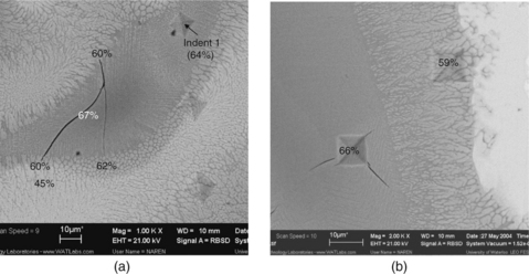
3.5 SEM micrographs of laser weld between Ti and Pt alloys, with Ti percentages indicated, showing (a) cracks formed during welding in the regions predominantly consisting of Ti3Pt but arrested in the regions predominantly consisting of TiPt and (b) cracks formed during hardness indentation in the regions consisting predominately of Ti3Pt.6
While the obvious choice from a welding/joining standpoint is to make a design using one consistent material, practical design, cost, and machining ability often dictate the use of many materials within a design. This use of a combination of materials is also evident even within wires and coils now used in many catheters, pacing leads, and sensors. In many of these components the material is a cored wire, sometimes referred to as a drawn-filled-tube (DFT). Common wire and coil materials in this category include Tantalum cored MP35N, Silver cored MP35N, Platinum clad Tantalum, and Platinum clad Titanium.
Materials introduced into during welding and joining, such as filler metals during brazing, need to be biocompatible as well. For example, in brazing of Zirconia tube to Ti-6Al-4V ferrule in developing an implantable neurostimulator, existing brazing filler metals, such as Ag-Cu-Ti series, can not be used due the toxicity of the fillers.7 Instead, a TiNi-clad braze, consisting of Ni/Ti/Ni laminated layers, is used since the braze becomes Nitinol, which is biocompatible, when the overall Ti/Ni ratio is 50:50.
A more thorough review of some medical devices and components, and the associated joining/processing challenges, is given in the next section.
3.3 Medical components and devices
Medical components and devices come in many shapes, sizes, and functions. The following section will highlight many current medical devices and the unique joining challenges they present.
3.3.1 Vascular devices
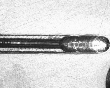
Vascular devices cover a broad range of the medical-device industry from catheters and guidewires to balloon angioplasty and stents. While guide-wires and catheters are generally single-use devices, stents are obviously permanent implants. For catheters the challenge is joining small diameter wires in a butt-weld configuration, often with subsequent sections having a smaller diameter. An additional challenge is that some sections may be made from unique materials. One such example is the joining of a 316L stainless-steel wire to a nitinol (nickel–titanium) end affecter. The nitinol can be formed or shaped to provide a certain function, while the 316L provides good torque transmission and lower cost for the long section of the wire. Alignment of the diameters to a center axis and control of the diameter in the weld zone can be difficult. An example of guidewire joining is shown in Fig. 3.6.
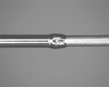
3.6 Guidewire for catheter applications. Note the change in diameter and smooth diameter across the joint zone (raw weld unpolished). The materials are NiTi and stainless steel.
Balloon catheters require the joining of the polymer balloon to a polymer tube on a guidewire. This can be achieved via direct laser welding or adhesive bonding. Challenges are the consolidation of the thin weld zone to develop high strength, and control of the initial gap between the components during fixturing. An example of a balloon welded to a lumen is shown in Fig. 3.7.
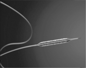
3.7 Balloon catheter joined to lumen expanding a laser-cut stent. Photo courtesy of AngioTech Corporation.
Stents are complex devices, typically laser cut from tube stock or welded assemblies of small wires. The stent is collapsed and delivered to the precise arterial location via a catheter and fluoroscopy, and then deployed and expanded in place. These devices pose the challenges of excellent surface and edge finish, control of heat-affected-zones (HAZ), and extreme control of orientation and laser cutting path. A laser-cut stent is shown in Fig. 3.8.

3.3.2 Pumps and sensors
A wide variety of external and internal pumps and sensors are now in use and in development. Insulin pumps and left ventricular assist devices have been in place for many years, with recent years seeing the development smaller-scale silicon-based drug reservoirs, MEM-based pressure sensors, and implantable RFID tags. Challenges include the welding and joining of metal and plastic foils, bonding fragile semiconductor layers to each other, assembly of microscopic circuit assemblies, and wire or tab attachments for interconnects.
3.3.3 Cochlear implants
Hearing implants are growing in use and are complex multicomponent devices. These units require sub-miniature voice coil and electronic assemblies, in addition to implantable circuit cans, lead wires, and even RF transmit units. Small-scale joining of wires, hermetic seals of enclosures, and assembly of small-scale wire coil assemblies are unique challenges.
3.3.4 Neurostimulators, pacemakers and defribrillators
These devices, while providing unique therapy to the patient, are similar in that they are generally composed of a hermetic ‘can’ which encloses the critical electronics, and metal wire leads that provide sensing or therapy delivery. The cans are implanted in a pocket in the upper pectoral region, or low in the abdomen. Wire leads are then threaded through the vasculature to the point where therapy is to be delivered. In the case of cardiac care devices the heart lead is implanted directly inside the right atrium or right ventricle to pace or shock the heart into normal rhythm, as shown in Plate I(a) (see Plate I in colour section between pages 300 and 301). In neurostimulators, the lead tip is implanted near the spine, or deep in the brain to control electrical signals that signal pain or to control tremors, as shown in Plate I(b).

Plate I (Chapter 3) (a) Typical implanted cardiac leads and (b) spinal nerve stimulation implant. (1) Pain signals; (2) IPG and leads; (3) SCS impulses and (4) (top) tingling sensations (parasthesia) to brain, (bottom) parasthesia. (courtesy of Boston Scientific)
Table 3.3 lists typical microjoining processes used to manufacture an implantable pacing system, which includes mainly a pulse generator and leads. The pulse generator includes a battery to generate electricity and circuitry to generate, control, and deliver the pulses, which uses many of the microelectronics packaging processes. The battery, however, is hermetically laser sealed to prevent leakage of chemicals (with a leak rate less than 1 × 10⁻⁹ atm-cc/s). Both the battery and circuitry are inside a titanium case that, again, is hermetically laser sealed to prevent human body fluids entering and causing corrosion. The internal circuits are connected through brazed joints such as Al2O3/Pt-Ir, to an outside connector block encapsulated in a biocompatible polymer such as polyurethane, and interconnected via Pt or Ti wires/ribbons using about 10–20 laser and resistance microwelds.
Table 3.3
Typical microjoining processes in pacemaker manufacturing
| Interconnecting and attaching | Battery | Wire bonding, soldering, adhesive bonding, resistance and laser microwelding |
| Circuitry | Wire bonding, soldering, adhesive bonding, ball grid array (BGA) | |
| Header | Brazing, laser and resistance microwelding, plastic joining | |
| Lead | Laser microwelding and adhesive bonding | |
| Hermetical sealing | Pacemaker, battery cases | Laser welding |
| Lead feedthrough | Ceramic/metal brazing |
These hermetic cans are Class III devices and designed for long-term implant in the body. The cans are typically thin-walled titanium or MP35N, while the leads are straight wires or coils of MP35N, titanium, or platinum-clad cored wires of tantalum, MP35N, or titanium. Ensuring a hermetic seal of the thin-walled case is not trivial, as the designs require welding near feed throughs, pins, or ceramic inserts. The case halves must fit together with minimum gap, and the welding process must track a non-uniform shape or seam. The weld penetration must be carefully controlled so as to not overheat nearby structures or penetrate too deeply and damage internal components.
An example of neurostimulators is the BION® microstimulator: a RF powered single-channel ceramic-cased implantable stimulator, which weighing just 0.75 g with an overall volume of only 0.19 cm3 (3 × 28 mm).7 It includes a ceramic to metal case, where the ceramic provides a window for RF transmission. The case, 2.44 mm in diameter, is composed of an 11.28 mm long Zirconia tube brazed onto a 0.76 mm long Ti cap (cathode) and a 1.98 mm long Ti ferrule (anode). The wall of the ceramic tube and the ferrule is 0.28 mm thick. After the electronic module is inserted into this case, a Ti lid is laser welded to the ferrule for the final hermetic seal.
The wire leads, which often have several conductor pathways running the length of the lead for sensing as well as delivering therapy such as pacing pulses or defibrillation shocks in cardiac leads, also provide a multitude of challenges. Laser and resistance welding, and mechanical joining are generally used to assemble these conductors and the associated components, such as electrical contacts and electrodes (Figs 3.9 and 3.10). Most of these joints must provide some level of mechanical strength as well as electrical conductivity. Materials must be biocompatible and corrosion resistant since most of the lead is in direct contact with the body or body fluids.

3.9 Typical welds and mechanical joints in a high-voltage tachycardia (shocking) lead which delivers both pacing and defibrillation therapy. (courtesy of Boston Scientific)

3.10 Typical welds and mechanical joints in a bradycardia or pacing lead. (courtesy of Boston Scientific)
The lead wires are often dual materials (clad cores), such as Pt–Ir coils coated with silicone rubber or MP35N-clad silver, and joined to pins, tubes, and other structures that are dissimilar material. An example is the termination of a coil wire for a heart pacing lead, in which the wire coil is MP35N-clad silver and the termination pin is 316SS. The weld is formed using a single laser-spot weld. Controlling the melt flow of the silver core can be a significant challenge if improper laser energy or poor targeting of the weld zone is used.
But, the most important consideration for any fusion weld between dissimilar metals is their metallurgical compatibility and the performance of the resulting weld deposit under service conditions. This is sometimes also referred to as weldability. The materials listed above are typically compatible with one another with the exception of the Titanium alloys. Titanium tends to form intermetallic compounds with many other transition metals such as Fe, Cr and Ni. These intermetallics are typically brittle and render the weld metal brittle. Often welds will crack immediately as a result of the thermal stresses generated during solidification and cooling. Figure 3.11 shows typical cracking in a resistance weld between a Ti-6Al-4V component and an MP35N wire.
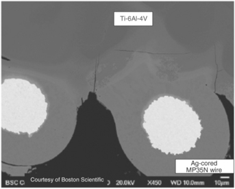
3.11 Weld between Ti and MP35N showing significant weld metal cracking due to Ti intermetallic formation. (courtesy of Boston Scientific)
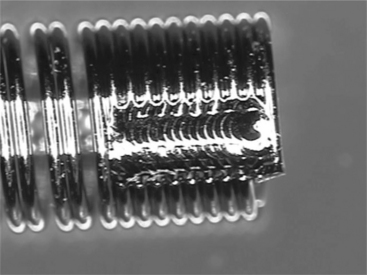
Several methods have been explored to improve the weldability of Ti to other metals. One approach is to optimize the resistance welding process to get a solid-state weld as shown in Fig. 3.12, in which the amount of molten weld metal formation and subsequently the amount of intermetallic is minimized at the weld interface. This is very similar to the solid-state welds formed in resistance welding of crossed Ni wires where the initial molten metal is squeezed out from the weld interface.8 Solid-state welding includes the forge-welding processes such as friction, magnetic pulse, and solid-state resistance welding. Friction welding has been successfully demonstrated for Ti to stainless-steel welding9 and resistance welding for Nitinol to stainless-steel welding.10

3.12 Resistance weld between Ti and MP35N wire with minimal admixed weld metal and no weld cracking. (courtesy of Boston Scientific)
Another approach is to use more compatible metals. Niobium, Ta, and Mo all form solid solutions with Ti and therefore are not prone to forming brittle intermetallic phases. Alternatively, these materials can be used as an intermediate material, or interlayer, to allow welding of an incompatible metal to Ti. Yet another approach to welding Ti alloys to other metals is to add a filler metal to intentionally manipulate the weld-metal chemistry and suppress the formation of intermetallic phases. One example is the addition of Ni to welds between NiTinol and stainless steel. Nickel enrichment of the weld metal suppresses the formation of the very brittle Fe2 Ti intermetallic phase and results in sound welds with comparatively good mechanical properties.11
3.3.5 Radioactive seed implants
Implant or internal radiation therapy, or brachytherapy, has been developed as an alternative to the traditional treatments such as radical surgery and external beam irradiation for cancer treatments. This technique uses a radioactive substance (e.g. in the form of pellets) sealed in needles, seeds or wires that are implanted directly inside or near the cancer. The cancer cells can be killed by the energy given off as the radioactive material decays. Figure 3.13a shows an example of such a seed implant developed for prostate cancer treatment. The radioactive substance is sealed inside Ti tubes by laser microwelding, as shown in Fig. 3.13b, in this case as the laser is well developed and suitable for such precision manufacturing.12

3.13 Radioactive seed implant: (a) schematic design and (b) laser welded assemblies.8
3.4 Joint design and process selection
As described in Sections 3.1 and 3.2, medical devices have unique requirements and use a specialized material set for biocompatibility and implant conditions. Many of the material and joint design configurations, however, are common across device types. The following sections will highlight specific assembly challenges and the selection of the microjoining processes best suited to achieve high-quality reliable assemblies.
3.4.1 Wire-to-wire assembly
Microjoining challenges manifest themselves at the assembly and joining stage. While small diameter wire and cable has been available for years, joining these small gauge wires to each other in either butt, overlap, or parallel (tipping as in a thermocouple) joint configurations and forming operational assemblies is a true challenge. Typical wire diameters may range from large at 0.100” to small at 0.0005” for the finest interconnect wires. Typical range for semi-automated assembly is 0.003–0.007”. Wire-to-wire assembly can be as simple as an overlap weld where both wire ends are flattened in the weld zone, to a uniform iso-diameter butt joint.
One of the best processes for joining butt-wire assemblies is percussive-arc welding. To form this type of weld, the following process steps are completed:
1. Cut the wire ends to form a tapered bullet or square face on the wire.
2. Straighten a short length of wire on each side of the joint. Careful axial alignment is required.
3. Accelerate the cut-wire faces toward each other, while simultaneously energizing the wires with opposing voltages; a current limit is also imposed. An alternative is to place a separate electrode between the wire faces with both wires opposite in charge to the center electrode. As the wire faces approach each other or the center electrode, an electric arc will form in the gap, and melt the opposing wire faces.
4. The wire faces are then allowed to forge together. Careful control of the force, the arc time, the closing velocity, and axial alignment are required.
Tipping of catheter wire, formation of thermocouples, and sensor wires can be completed in a similar manner. The heat source can be an electrical arc, or even the heat of the plasma formed at the tip of a micro-plasma torch. Laser energy can also be directed at the tip where a small portion of the wire end is melted. Natural surface tension causes the molten pool to pull back and form a uniform sphere. This approach works best when the two wires are straight, parallel with each other, and form an isomorphous alloy in the melt zone. An example of catheter tipping is shown in Fig. 3.14.
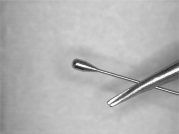
3.14 Tip forming of a catheter wire. The formed end can be made using laser or arc processes followed by precision grinding to final shape.
For these types of small-scale wires, arc processes work very well. The small size of the wire helps direct or draw the arc only to the wire tip. Laser-weld spots are generally much larger in diameter than the wire. Because the laser can have a non-uniform energy distribution across the weld spot (Gaussian), the location of the wire to the beam can be non-optimum. Further, the laser welds and cools over a short timeframe, and minimizes the weld zone. In these types of assemblies this can lead to a marked gradient in grain size from the fusion ball to the parent material in the wire. Arc and plasma processes tend to add more heat, softening the grain transition from the welded ball to the parent wire. This improved gradient in microstructure can result in improved toughness and fatigue performance of the final assembly.
3.4.2 Wire-to-pin assemblies
In this application the wire can be straight or in the form of a coil. The wire is then joined or terminated to a pin or other solid substrate, such as a jumper pad on a hybrid circuit or a header block where pacer leads are plugged in. The wire is often in the shape of a coil spring to improve flex fatigue and other mechanical performance attributes.
One of the best processes for this type of assembly is resistance welding. In this process oppositely charged electrodes are applied under force to the wire, and current is discharged through the wire to the interface. Resistance to the flow of current causes localized heating, resulting in weld formation where the resistance is highest (usually at the interface of the wire to the substrate). The clamping force used in resistance welding is a key advantage in that is directs the weld location, and consolidates the molten or softened metal to form a concise nugget. Gap is not such a problem as the forces used to clamp the electrode against the parts close any excessive gap. Further, as the materials are heated and soften during the first few milliseconds of the current application, additional joint consolidation occurs. Key challenges are the control of the current path in the often, small diameters, especially when direct access for the lower electrode is not possible. Electrode size, position, and force are also issues in that the electrode face often is larger than the wire to be joined. Careful construction of the electrode face and radiusing of the electrode corners can help define the precise weld zone to just a few wire diameters. Disadvantages are the development of small electrodes, electrode wear, and positioning the wire-substrate assembly prior to joining. An example of a titanium-wire resistance welded to a Ti-6/4 terminal block for a pacemaker application is shown in Fig. 3.15.
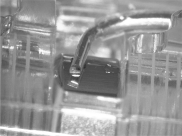
3.15 Resistance spot weld of 0.005” titanium wire to Ti-6AI-4V terminal block in the header of an implantable pacemaker.
Laser welds are also used for wire to substrate bonds, as they are readily automated and simple to align and target. Both welds are used in the assembly of shocking coils used in defibrillation leads for implantable heart failure devices. A disadvantage of the laser-weld process is the lack of clamping force holding the wire in place against the surface. If the wire is not in good contact with the surface, there is no driving force to ensure wetting and flow of the wire to the surface. Conversely, the driving force is surface tension in the molten wire, which pulls back from the surface, forming a balled end to the wire. An example of this common defect is shown in Fig. 3.16.
3.4.3 Hermetic sealing of electronic enclosures
A key similarity in many medical devices is the need for a small thin-walled can or container to hold the necessary electronics, power supply, batteries, capacitors, and other circuit functions. This package must be hermetic to at least moisture ingress, but is typically gas tight to even low volumes of helium. Typical housings in medical are MP35N, 316L, or, the most common, commercially pure titanium. Hermeticity is required to ensure moisture attack cannot cause corrosion and eventual shorts or opens of the circuits. Note that many hermetic enclosures in use today also incorporate getters for oxygen and moisture, to improve long-term reliability and quality. Regardless of the sealing technique, a minimum of 50% spot-to-spot overlap is recommended, with 75–80% overlap common practice. Also note that the important aspect is to achieve overlap of the weld zones at the interface of the joint. Overpenetration of individual spots detrimental and penetration does not correlate to hermeticity; it is the continuity of the seal at the interface. This is shown schematically in Fig. 3.17

3.17 Overlap condition (OL) requirement to achieve full hermetic weld at the interface of the weld joint. In general 50% overlap on the surface is the minimum to achieve uniformity at the interface. dw – Weld diameter.
Three processes have been widely used to hermetically seal thin-walled medical cans:
Resistance welding is an excellent choice when the can materials are resistive as in the case of MP35N or 316L stainless steel. Opposed electrodes are clamped against a flange of the housing and slowly rotated to traverse the length of the package. Current and voltage is applied to form overlapping resistance weld spots. After the first pass along two parallel sides, the electrodes retract, the part rotates 90 °, and the process is repeated along the two remaining sides. Circular packages can also be sealed with this technique. Disadvantages of the process are the requirements for a flanged cover, which is often nickel and gold plated. In this manner the resistance weld is actually a resistance braze, forming a eutectic alloy of gold–nickel at the interface. This allows the process to run somewhat faster and use less heat input than full fusion welding of the higher melting point MP35N or 316L stainless steel.
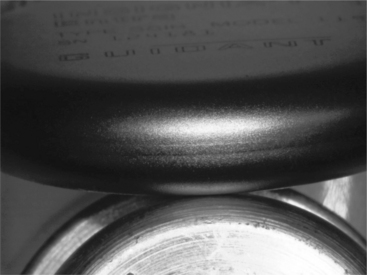
Plasma welding has hermetically sealed more medical pressure bellows than any other process. Pressure bellows are formed from a stack of preformed thin metal discs, sealed along their periphery. In a manner similar to arc processes for sealing wire tips, the arc is drawn to the sharp edge of the disc, melting and sealing the disc edge. The process produces a weld seam very similar to pulsed laser welding, but with slightly increased heat input. It is an excellent process for sealing flanged enclosures as well. Its disadvantage is the heat input for deeper penetration welds, and the close proximity of the torch face to the weld zone itself.
Laser welding is today the most popular and easy to implement for hermetic sealing. Advantages are the ease of “point-and-shoot” line of sight welding capability, and the ease with which automation can track odd package shapes and configurations. Deeper penetration welds can be developed without overheating critical glass or ceramic feed-throughs, and weld cycle time is the shortest for laser welding. Disadvantages are often the initial start up capital cost, training and laser safety requirements, and the need for excellent part fit-up. A general rule of good laser welds is the joint fit-up must have a maximum joint gap of 10% of the thinner material. Excessive gaps cause the laser to punch through one layer causing a hole, or the edges of the seam pull back due to the molten material surface tension. An example of a seam weld with too much gap is shown in Fig. 3.18. Note the smooth-balled edges on each side of the seam. An example of a well-formed hermetic seam weld is shown for a pacemaker pulse generator in Fig. 3.19.
3.4.4 Cutting and drilling shapes and holes
The laser can also be used to cut and shape tubes for form unique scaffold like structures such as stents or abdominal aortic aneurysm (AAA) grafts. These lasers are unique configurations that develop very small spot sizes with extremely high peak powers. The small spot size minimizes the cut kerf and improves the cut-edge quality, while the high peak pulse power fully penetrates and ejects a plasma plume of material. The automation and computer control of the laser allows for the development of full 3-D structures. The cut-edge quality is critical in these applications, and post-cutting polishing and honing processes are often used to ensure smooth, burr-free edges. However, the proper selection of pulse rate, table feed rate, cover gas type, and cover gas pressure all contribute to cut-edge quality.
3.4.5 Ring-to-ring or tube-to-tube assembly
There are many instances in medical devices where the mating components are thin-walled tubes that slide into one another. Arthroscopic tools, catheters, and electrodes on pacing leads or terminals are examples of this application. Two joining processes are generally used to join these thin-wall structures. First and foremost is laser welding. The laser can be used to form single or overlapping spot-welds that join the outer tube to the inner tube. The wall thickness of the electrode can range from 40 to 75 µm. Here again the advantages of the laser are the ease of point-and-shoot process development, with the disadvantage of joint fit-up. If the inner ring is not in close contact to the outer tube, the laser will simply cut a hole in the outer layer, with little or no mating connection developed.
A newer process originally developed for larger-scale automotive applications is magnetic pulse welding. In this process magnetic fields are set up in the inner tube such that the repulsive force to an inner mandrel explosively forces the inner layer outward forming a solid-state bond to the outer layer. The larger-scale version of magnetic pulse welding has been used to form flares and expanded regions in cooling tubes and muffler components. The small-scale version is an excellent choice for bonding inner tube structures to outer electrode rings. An advantage of this process is the low heat input, rapid cycle time, and continuous weld over the entire mating surface. Disadvantages are that the application works primarily for round conductive components and requires unique fixturing.
3.4.6 Polymer tube-to-tube assembly
Polymers are used throughout medical devices, especially for single-use disposable devices such as catheter sheaths, packaging, and insulators over wire components. One of the simplest and most widely used joining processes is adhesive bonding. Joint design challenges are especially evident where polymeric materials must be joined to metal components. Common practice is to clean and prepare the surface of the metal, and then join a tube over the metal and bond it in place with liquid adhesive. Here again the gap at the interface can define success or failure. In most cases the design extends the bond area to ensure adequate surface area for the bond to occur. Studies have shown that for optimal bonds, a uniform gap should exist to provide a uniform adhesive-layer thickness. Too thin an adhesive layer yields poor surface coverage and low strength. Similarly, too thick an adhesive layer yields low strength due to failure of the adhesive itself. Careful analysis of the bond failure is critical to development of the proper process and achievement of a robust design.
Balloon catheters are another example of polymer-to-polymer joints; this time joined using full fusion processes. A simple heated mandrel/clamp can be used to fuse the joint region, but newer methods using focused infrared light in the form of a laser or IR lamp are commonly used. The non-contact feature of the infrared welding process is an advantage for medical grade devices.13 Cross-contamination of the heated tool approach is a serious defect, and careful tool and heat controls are required to keep the tool face clean and to avoid transfer to the next welded device. CO2 laser systems are common in this application as most polymers have strong absorption bands near the 10.6 micron output of the CO2 laser.14 In CO2 and some diode welding, the polymer itself absorbs the laser energy, causing the development of a fusion zone. Other wavelength diode lasers and standard ND:YAG systems can also be used, especially when welding onto metallic components.
3.4.7 Polymer tube-to-solid-pin assembly
When ND:YAG is used, its 1064 nm wavelength is usually transmitted through the polymer with very little absorption and heating. In this case the ND:YAG is focused on an internal metallic mandrel and heated with the laser. The thermal energy then conducts to the polymer layer forming a bond.15 In this manner the process is referred to as through transmission infra red welding (TTIR). Additional research has been completed on specific laser absorbing dyes that can be molded into the plastic parts or provided as a thin interlayer. In this application the laser is absorbed at the dye layer, and thermal conduction then heats the surrounding materials to form a weld zone. Note that in all polymer welds, the fusion zone must be held in compression while the nugget cools in order to achieve the best weld strength. The high expansivity and poor thermal conduction of polymers make this compression requirement vital to the development of good welds.
3.4.8 Polymer bags and enclosures
Numerous medical devices are fabricated using all polymer systems. These include intravenous fluid bags, drug delivery, microfluidic canisters, pumps, and filters. Sealing and welding of thin films to each other and to structural plastics is a common requirement. Early processes used simple heated bar or heated formed tools to compress the weld zone. However, cross-contamination from the tool face is a serious issue so non-contact methods were developed. Non-contact includes the aforementioned laser welding, but two of the most popular methods are radio-frequency (RF) dielectric welding and ultrasonic plastic welding.
In RF dielectric welding the process relies on the chemistry of the polymer itself. In this process an oscillating RF electric field is imposed on the weld joint. The polymer chains react to the imposed field, and the dipoles of the polymer attempt to align with the field. The polymer dipoles cannot oscillate in time with the applied field and this hysteresis loss causes rapid heating.16 Benefits of the technology are fast cycle time, good weld-zone control with the applied clamping force, and the tool is cold so transfer and cross-contamination is eliminated. This process is commonly used for final packaging of devices prior to shipping.
Ultrasonic plastic welding uses a medium frequency transducer horn and clamping force to develop a weld zone. The ultrasonic energy is applied typically at 20 or 40 kHz depending on the component size, shape, and wall thickness. Similar to RF dielectric heating, the ultrasonic energy vibrates the polymer chains, causing rapid heating and development of a weld zone.17 Here again the applied clamping force forges the molten zone together to form an excellent seal and weld. This process can be completed on virtually all thermoplastics.
3.5 Testing and verification
The first consideration is mechanical performance of the welded assembly. Although there are no standardized performance requirements for implantable joints, there are common performance considerations for all designs. For example, any joint must withstand any subsequent manufacturing steps and handling. The loads imposed during manufacture may in fact be far greater than loads seen during service. The loads imposed during the implant procedure are often more severe than those seen chronically. Handling by the physician as well as the interaction of the lead with delivery tools and/or the anatomy is largely uncontrolled and considerably variable. For example, on occasion, implantable leads must also be removed for various reasons. Perhaps some of the most extreme loads can be seen during an explant procedure when simple traction may be used to pull the lead out. Tissue ingrowth and encapsulation can anchor parts of the lead making them more difficult to remove. If a part of the lead was to break off during extraction a significantly more invasive surgery may be required to retrieve it. This puts the patient at a significantly higher risk of harm. All of these service conditions should be understood and considered when designing joints for implantable leads.
Implantable joints are often tested in manufacturing using small-scale tensile-testing equipment. During pull testing, the actual joint is often exposed to a complex stress state, resulting most often in tensile shear of the weld zone. It is important in small-scale welds to consider the effect of the weld process on the raw parent material strengths. As a general rule, full fusion welds yield approximately 60% of the raw parent material strength, in tension. In practice, the ‘pull test’ can apply off axis loads and stresses, leading to failure at lower than expected loads.18 Peel testing is especially stressful, as the load is focused on a narrow zone of material, which tends to tear and unzip along the weld interface. Even though the weld-zone formation is the same, peel test samples may fail at 25% of the load applied in direct tension. A schematic of this effect is shown in Fig. 3.20. As the stresses are effectively applied to smaller and smaller areas of the joint or weld zone, the test strength decreases. The point here is to carefully document the testing procedure and provide adequate controls to apply the test force in a consistent and uniform manner.
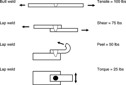
3.20 Schematic of test conditions and the effect of loading condition on measured weld strength for a uniform area weld zone.
In practice, small-scale joints typically have two failure modes. In the first, insufficient mixing across the interface leads to a small interface area to carry the applied load, so the joint fails. In this case the mating faces of the joint show very little transfer of material and it is obvious to the process and quality engineer that welding was insufficient. Overwelding is also an issue. Weldments generally exhibit a horseshoe form when plotted as strength versus power. At low power the weld has no strength due to lack of weld zone development at the interface. At some point, optimum welds will yield the highest strength. This occurs where the weld zone at the interface is optimized relative to the loss of parent material strength. With the application of too much power, the weld zone penetrates deeper and overheats the parent materials, causing parent material failure adjacent to the weld zone. This is often thought of as a “good” weld, even though the parent material has been seriously degraded from its original condition. The reader is encouraged to optimize the weld zone and parent material performance, and neither underweld or overweld these critical assemblies.
Another leading consideration for welds in implantable components and devices is corrosion performance. The corrosion performance of the weld metal should not degraded by the thermal cycle of welding. The primary concerns are excessive oxidation and/or dealloying due to weld-metal contamination. Excessive reaction between the molten weld metal and the welding atmosphere or surface contaminants can largely be avoided by using high-purity shielding gases and cleaning the joint surfaces thoroughly prior to welding. Polymeric materials such as silicone rubber, polyurethanes, and adhesives, which are commonly used in the construction of leads and other medical devices, are another potential source of weld contamination that should be considered and avoided.
Corrosion performance can be evaluated with a number of in vitro, or bench, testing approaches. ASTM F2129 is a potentiodynamic polarization test that evaluates the breakdown potential and pitting corrosion characteristics of a metal or assembly. ASTM F746 is a test for pitting and/or crevice attack. Simple soak testing in saline or simulated biological fluid can also be used to evaluate general and galvanic corrosion. ASTM G71 provides general guidance for galvanic testing. Current-induced corrosion testing specifically evaluates material and assembly performance under the service conditions of delivering electrical stimulation therapy. For example, a cardiac lead may need to deliver chronic pacing therapy at 70 pulses per minute for 10 or more years. Under these conditions the cumulative corrosion could be significant for components or assemblies exposed to the pacing charge. The setup and duration of this testing should be sufficient to replicate the maximum cumulative charge that would be seen over the expected life of the implants.
As is the case for all implantable medical devices, in vivo testing is an important approach for evaluating the corrosion performance in the actual biological environment at the component, assembly, and complete lead level. It is highly recommended that any in vitro corrosion testing be supported with some level of in vivo testing.
3.6 Conclusion and future trends
Microjoining is a critical and enabling technology for manufacturing of medical implantable components and devices. The small scale of many emerging designs requires a deeper understanding of joining technologies and thin materials so that the proper joining method can be applied.
Lack of standardization in polymeric materials will slow the development of many new devices. Polymeric materials generally must meet a melt-flow index and density, but joining properties can be greatly affected by flow enhancers, regrind content, lubricants, etc. Material purchased to similar specifications from multiple vendors often do not perform with equal results. Polymeric materials must approach the compositional rigor imposed by metals standards to enhance their use in medical devices.
Joint designs for metals and plastics should also be developed and shared across the industry. Guidelines for joint-fitup, gap tolerance, weld penetration, and heat input would help improve overall quality and reliability of medical devices.
The weldability data given in Figs 3.1 and 3.2 should be expanded upon, especially for dissimilar material combinations. Further, that database should be driven by welding technology, as some small-scale laser welds cool so rapidly, the process can violate what the handbooks would indicate as weldable.
Biocompatibility and corrosion performance of joints should be studied and a database of performance presented to the medical industry. Many materials could be used for certain applications, but since compatibility is governed from a device level, some material choices are neglected because they must replicate what has been used in the past. This regulation limits the use of new materials until an overall design is approved.
Fatigue performance and testing of implantable devices is an area of increasing concern. Many devices see significant cyclic stresses associated with cardiac/vascular or musculoskeletal motions. For example, the average person’s heart beats approximately 400 million times during the 10-year expected life of many cardiac leads. Muscle contractions can be strong enough to crush a pacemaker or ICD pulse generator can and may repeat thousands of times depending on the activity level of the patient. As devices trend toward small and thinner designs the cyclic stresses on components and joints can become increasingly severe. This has been highlighted by several recent high-profile product recalls associated with fatigue failures of device components. Consequently, regulating bodies and standards will be increasingly focused on fatigue performance and testing.
Lastly, a key future trend in medical devices is a push toward more automated assembly processes. Current practice of manual assembly places high requirements on training and inspection processes. The use of automation has the potential to improve overall quality and reliability by removing the human element and inherent variability of manual processes.
3.7 References
1. FDA Classifications for Devices, www.fda.gov.
2. Ratner, B.D., Hoffman, A.S., Shoen, F.J., Lemons, J.E.Biomaterials Science. Academic Press, 1996.
3. Carter, G.F.Principles of Physical and Chemical Metallurgy. American Society of Materials, 1979.
4. ASM HandbookProperties and Selection of Non-Ferrous Alloys and Special Purpose Materials. ASM International, 1990. [Vol. 2].
5. Li, X., Xie, J., Zhou, Y. Effects of Oxygen Contamination in the Argon Shielding Gas in Laser Welding of Commercially Pure Titanium Thin Sheet. J. Mater. Sci.. 2005; 40:3437–3443.
6. Noolu, N.J., Kerr, H.W., Zhou, Y., Xie, J. Laser Weldability of Pt and Ti Alloys. Mater. Sci. Eng. A. 2005; 397:8–15.
7. Jiang, G., Mishler, D., Davis, R., Mobley, J.P., Schulman, J.H. Biomed. Mater. Res. Part B: Appl. Boiomater.. 2005; 72B:316–321.
8. Ely, K.J., Zhou, Y. Microjoining in Medical Components and Devices. In: Zhou Y., ed. Microjoining and Nanojoining. Woodhead Publishing, 2008.
9. Fukumoto, S., Zhou, Y. Metall. Mater. Trans. A. 2004; 35:3165–3176.
10. Fuji, A., North, T.H., Ameyama, K., Futamata, M. Mater. Sci., Technol.. 1992; 3:219.
11. G. Wang, “Welding of Nitinol to Stainless Steel” SMST-97, Proceedings of the Second International Conference on Shape Memory and Superelastic Technologies, eds. A. Pelton, T. Duerig, D. Hodgson, and S. Russell (Pacific Grove, CA: International Organization on SMST), p. 131.
12. P. Hall, “Laser Welding Nitinol to Stainless Steel” SMST-2003, Proceedings of the International Conference on Shape Memory and Superelastic Technologies, eds. A. Pelton and T. Duerig (Pacific Grove, CA: International Organization on SMST), p. 219.
13. Grimm, Robert A.IR Welding of Polymers. MDDI, 2001. [May].
14. Heimenz, P.C.Polymer Chemistry. Marcel Dekker Inc., 1984.
15. Kagan, V.A., Bray, R.G., Kuhn, W.P. Laser Transmission Welding of Semicrystalline Thermoplastics. Journal of Reinforced Plastics and Composites. 2002; 21:1101.
16. Mistry, K. Plastic Welding Technology for Industry. Journal Assembly Automation September. 1997; 17(3):196–200.
17. Ultrasonic Welding of Plastics Used in Medical Devices. Welding Technology Institute of Australia, 2006. [TGN-MS-04, Rev 0, April].
18. Dieter, G.E.Mechanical Metallurgy. McGraw Hill Company, 1986.