
Bonding strategies and adhesives for joining medical device components
Abstract:
Implanted medical devices rely on many different and complex joints between dissimilar materials. Adhesives provide one solution for creating such joints. While long-term implants have the advantage of being in a constant-temperature environment, these adhesive joints need to meet the additional challenges of complex loading conditions and ever increasing device-lifetime requirements. The principles of joint design, namely avoiding peel and cleavage-loading conditions, must be scaled down to meet the ever decreasing device sizes. Because the long-term reliability of an adhesive joint under wet fatigue loading conditions generally scales with the adhesion strength between the adhesive and the substrate, surface modification strategies are often employed to improve joint strengths. Any primers or adhesives must meet the biocompatibility requirements which in large part address leachable toxicity. As a result, the use of many fast- or light-cure adhesives is very limited in long-term implant applications. As such, the industry is constrained to relatively few adhesive chemistry options. In this chapter, we review joint design strategies, present methods to test the adhesive strength, discuss methods for improving adhesion strength and provide lessons learned from examples of joints.
14.1 Introduction
In many respects joining polymers in medical devices is similar to bonding in other applications such as automotive, aerospace, and construction industries. Obvious considerations are made for regulatory-agency requirements, body-contacting applications, and necessary durability testing. Generally, dissimilar materials can be joined through many different methods. Joints can be mechanical, riveted, screwed and clamped; they can be welded with temperature and pressure; they can be formed by applying an adhesive to the interface, or they can be solvent bonded. In each case, joint design is the single most important factor in determining the overall strength of the joint. When using an adhesive, wettability and intimate contact are required to harness both mechanical and van der Waals interactions that maximize the bond strength. Surface treatments, such as gas-plasma modifications and primer coatings, are used to engineer the surface energetics of the substrates and to, potentially, create covalent bonds at the adhesive interface. Solvent-bonding techniques require thermodynamic compatibility between the two substrates and the selected solvent. Testing the strength of the adhesive bond and predicting durability over the life of a medical device is critical to assessing the performance of both the adhesive and the substrate surface treatment.
Adhesives have many advantages over other methods of bonding. They offer a more uniform stress distribution across the joint and improve fatigue performance. Adhesives are also compatible with complex geometries and joint designs. In many cases, adhesives are used because of their ease of assembly, particularly pressure sensitive adhesives (PSAs). Furthermore, adhesives are used because they can electrically insulate, dampen, seal and enable the bonding of heat-sensitive materials. Joints designed with an adhesive bond can be stiffer than those made with other joining technologies. The integrity of an adhesive joint is critically dependent on the surface preparation. Further cautions for designing with adhesives include possible toxicity of adhesive components and partially cured adhesive (particularly UV initiators in fast-cure chemistries), slow processing time, a lack of non-destructive quality control, difficulty reworking a joint, and a tendency for adhesive joints to fail with excessive thermal cycling.
In this chapter we will discuss how to design an adhesive joint, how to engineer the adhesive–substrate interface for maximizing bond strength and durability, and how to test an adhesive joint to predict its reliability for use in a medical device. Furthermore, the adhesive classes available for use in the medical-device industry will be reviewed.
14.2 Designing a joint with adhesive
The key design rule for an adhesive joint is to eliminate peel or cleavage forces. Adhesives perform poorly under peel and cleavage-loading conditions. To prove this to yourself, take a piece of tape and adhere it to a flat surface, with one end sticking off the edge of the surface. Pull the end back towards the end that is adhered to the surface. By doing this, you are putting the adhesive in peel or, more precisely, a 180 ° peel geometry. It is easy to remove from the surface. Adhesive joints perform best in shear-loading conditions. To demonstrate, re-adhere the tape, or start with a new piece. Pull the free end straight back toward you, keeping the force parallel to the surface. Now you are putting a shear load on the adhesive bond. You can likely apply a force large enough to break the substrate (tape backing). This is a simple demonstration that is intended to reinforce the point that joint design is the single most important factor in determining the joint strength.
There are four basic types of loading conditions for a joint.1 These are shown in Fig. 14.1. Because use conditions vary, most joints experience multiple loading conditions and environments. Therefore, it is critical to understand the most severe loads and design the joint to minimize peel and cleavage forces.
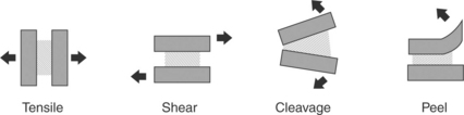
14.1 Loading conditions for an adhesive joint. The substrate is shown as solid, the adhesive is represented by the patterned area, and the loads are shown with the arrows.
Tensile loading occurs when the plane of the adhesive is oriented perpendicular to opposing forces. Failure typically occurs when a crack or defect at the highly stressed outside edge propagates. In practice, designing joints to be in pure tensile is challenging. First, rarely are loading conditions known to be perfectly parallel. Any asymmetry in the loading conditions puts the joint into cleavage mode, resulting in lower than anticipated failure strengths as compared with joints tested in tensile-mode conditions. Second, it is difficult to control the bondline thickness. Any variability in the bondline thickness will put the joint into cleavage, reducing the failure strength of the bond. The tensile strength is measured as ultimate failure strength per bonded area (load/area).
Shear loading occurs when the loading forces are acting parallel to the plane of the adhesive. Joints are generally strongest when in shear because the forces are distributed across the entire plane of adhesive. Failure occurs when a crack or defect at the highly stressed leading or trailing edge propagates. The stress on the edges can be reduced, thus increasing the efficiency of the bond by tapering the thickness of the substrate and the leading and trailing edges.2 The strength of the adhesive bond scales with the bonded area. The shear strength is measured as ultimate failure strength per bonded area (load/area). There is an optimum bondline thickness that should be evaluated with the adhesive and substrate combination being considered.3 Too little adhesive and the bondline can become adhesive ‘starved’ and the result can be low joint strength. Too thick of a bondline is described as ‘adhesive rich’. A thick bondline can be subject to plane strain conditions and any cohesive weakness of the adhesive layer can dominate the overall joint strength. The optimum bondline thickness will be somewhere between the adhesive starved and the adhesive rich regimes and will maximize joint strength. The bondline thickness is typically controlled through the use of molded-in standoffs in the joint. For test-level specimens, glass beads or fibers are often used to control the bondline thickness.
Peel and cleavages forces are always undesirable.4 This loading situation occurs when the applied load acts to pry the adherends apart. The peel condition occurs when one or both of the substrates or adherends is flexible. Cleavage occurs when the substrates or adherends are rigid. Joints loaded in peel/cleavage offer considerably lower strengths than joints loaded in shear. This is because in peel/cleavage the load is concentrated on the small leading edge of the joint. The units used for recording the strength of this type of bond are indicative of this concentrated load. Rather than reporting the joint strength in load per bonded area as is done for tensile or shear conditions (load/area), these joints have strength reported as load per width of bond (load/width).
Joint design is the single most important factor in determining the overall bond strength. Guidelines for joint design include:
• Design the joint such that operating loads stress the adhesive in shear.
14.2.1 Assessing how adhesive joints fail
It is important to understand how the joint has failed during service before deciding a course for corrective action. The mode of failure will reveal the weakest link in the system and dictate the course of action for an effective redesign. Adhesive joints can fail in four main ways as shown in Fig. 14.2. Joints can fail cohesively within the adhesive. This failure mode occurs when the crack propagates through the bulk of the adhesive. Joints can fail adhesively. This failure mode occurs when a crack propagates along the adhesive bond interface, between the adhesive and the substrate. Joints can fail cohesively within the substrate or the adherend. Finally, joints can fail in a mixed mode, where the crack wanders, propagating through all three areas, the adhesive, the interface and the substrate. A mixed-mode failure is most often a result of complex loading conditions. Generally a substrate or adherent failure mode is considered desirable, as this indicates that the adhesive joint is stronger than anything else in the system and joint design can be considered successful. Be careful making such assumptions. The strength of an adhesive bond is extremely rate sensitive. Bond strengths must be tested in a manner that simulates both the load distribution and the failure mode of the actual use situation. For example, if a joint in a medical device is subjected to in vivo wet cyclic loading conditions, producing adhesive failure at the interface between the adhesive and the substrate, then testing that same joint, wet or dry, in a manner that produces cohesive failure (failure within the adhesive layer) teaches nothing about the joint strength in the use condition. That is, in the use situation the failure is between the adhesive and the substrate, while the simulated test conditions result in a crack propagating through the adhesive itself. The different path of crack propagation makes it impossible to compare the in vivo situation with the in vitro test situation.
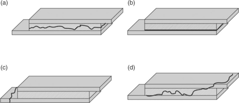
14.2 When the crack propagates through the adhesive layer (a), the failure mode is cohesive. When the crack propagates at the interface between the adhesive and the substrate (b), the failure mode is adhesive. When the crack propagates through the substrate or adherend (c), the failure is cohesive within the substrate. When the crack is not well controlled (d), mixed mode failure occurs. Mixed mode failures often result from complex loading conditions.
In the medical-device world, the choices for substrates and adhesives are relatively limited. When selecting an adhesive–substrate combination, it is desirable to create model test systems that isolate the loads to a single condition (see ASTM standards). These simplified joints allow one to apply uniform loading conditions across the joint and to assess the weakest link in the system. In these model systems it is quick and easy to assess the available combinations of substrates and adherents against the primary loading conditions to select the optimal joint materials.
14.2.2 Measuring the work of adhesion (G0)
Adhesive forces are the forces that hold two materials together at their surfaces. Cohesive forces are the forces that hold two adjacent molecules of a single material together. The work of adhesion is defined as the energy required to move two surfaces out of contact. If this is measured as force verses displacement, the work of adhesion is the integrated area under the curve. However, if not performed carefully, these force verses displacement curves are more representative of the practical adhesion than the true work of adhesion.5 Practical adhesion refers to the total amount of energy measured when the joint is destroyed. Why does the work of adhesion differ from the practical adhesion? Because when a joint is pulled, often many other deformation forces are measured in addition to the interfacial deformation force. Equation [14.1] describes the relationship between the practical adhesion, the work of adhesion, and those additional deformation forces.6

Because most adhesives are polymers that have a strain-rate dependence due to their viscoelastic nature, the rate of testing must be considered when trying to isolate the work of adhesion. Therefore Equation [14.1] can be re-written as follows:
The first term in the equation represents the work of adhesion and the second term represents the work of mechanical deformation and/or damage. The work of adhesion will be isolated when the rate of testing approaches zero. Likewise, increasing the temperature will minimize the contribution of forces of deformation for a polymeric substrate. A thought experiment to demonstrate this point is to pull a rubber band between your fingers. The deformation of the rubber band results in a measurable force. Now imagine the rubber band is bonded to your table top. Pull up on the loop and the rubber band deforms as the bond to the table top releases. When measuring the total energy required to delaminate the rubber band, what portion of the total energy is due to stretching the rubber band, and what portion is the energy required to delaminate the bond? Which force is dominating the measurement? By minimizing the energy that the rubber band contributes to the total energy measures, one can isolate the energy required to pull the bond from the table; that is the work of adhesion (G0).
One of the most common adhesives in the long-term implanted medical devices is silicone medical adhesive. Two common substrates for these long-term implants are both polyurethane and titanium. Many pacemakers, defibrillators and neurological stimulators are designed using medical adhesive to seal the joint between the polyurethane connector module and the titanium can as shown in Fig. 14.3. The silicone medical adhesive must maintain bonding to both polyurethane and titanium for the life of the device, which can be as long as 15–20 years for systems with rechargeable batteries. Insulated electrical leads that carry the energy from the device to the heart/spine can place cleavage-loading conditions on the joint. For this reason, ‘pin and strap’ technology is used to secure the connector module mechanically to the can. ‘Pin and strap’ is a mechanical fixation strategy. The adhesive is supplemental, providing a seal, and is not load bearing due to the poor performance of adhesive joints in cleavage, a poor loading condition for adhesive alone.
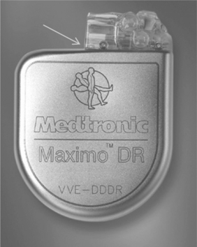
14.3 An acetoxy cured silicone medical adhesive is used to seal the interface between the titanium device and the polyurethane connector module. The arrow indicates the adhesive joint that is filled with medical adhesive.
Due to the extreme in vivo conditions (cyclic fatigue at 1 Hz) and the expanding implant times, improvements in the strength of this bond are always desired. To test the strength of the medical adhesive bond to each of the substrates, the silicone medical adhesive is applied to the surface of the polyurethane or the titanium in separate experiments. Because this bond is most susceptible to an adhesive failure mode, one way to improve the bond strength is to apply a primer to the interface between the silicone medical adhesive and the substrate (polyurethane or titanium). To evaluate a series of possible primers, it is important to measure the work on adhesion—the energy required to separate the two interfaces in contact. To measure the work of adhesion, the bond must be pulled in a manner that allows the crack to run along the interface. We can use the poor performance of joints in the peel-loading condition to our advantage in such evaluation tests were we to want to understand the interfacial energy of adhesion (i.e., the adhesion force between the substrate and the adhesive).
Here is a thought experiment. Suppose you want to evaluate three different primer systems against a control joint having no primer to understand if there is room to improve the interfacial bond strength. You place the device shown in Fig. 14.3 in the clamps of an Instron and measure the force as a function of grip displacement, loading the interface in tensile. The control joint failed at a lower energy than the primer joints, but there was no difference in measured failure energy for the three primer systems. You examine the failure modes. The control failed adhesively – at the interface. For all three primer systems, there is adhesive on both sides of the interface and you conclude that the joint failed cohesively within the thickness of the adhesive. Because the cohesive strength of the adhesive was not variable in the primer experiment, the result was no measured difference in the energy of bond failure for the three primer samples. How does one evaluate which primer is most effective? To evaluate the primer the crack must propagate through the interface where the primer was applied. Putting the joint in peel gives the best chance of creating an adhesive failure mode. Think back to the tape adhered to the table experiment. The joint is weakest in peel; therefore, it is desirable to put an adhesive in peel when trying to evaluate the strength of the interface. Furthermore, to measure G0; all deformation forces must be minimized.
Figure 14.4 shows the sample configuration for measuring the work of adhesion between the flexible silicone medical adhesive and a rigid substrate like polyurethane, 75D durometer. The flexible wire mesh imbedded within the silicone medical adhesive minimizes the forces generated by stretching the bulk of the adhesive. The crack can be initiated and the energy required to propagate a peel crack in the medical adhesive at the polyurethane interface can be measured.

14.4 Sample configuration for measuring G0 for a flexible silicone medical adhesive bonded to a rigid substrate.
This bond can be loaded into an Adhesion Durability Tester (ADT)7 to test the bond in peel, under creep (low-strain rate – to minimize extraneous deformation forces), and in water at body temperature. Such conditions give a good correlation to low-strain cyclic loading in vivo. That is, bonds that perform well in this test tend to have long in vivo durability. The ADT was designed to produce adhesive failures, mimicking the most common failure mode observed in vivo. Figure 14.5 shows a schematic of the ADT, where a linear voltage displacement transducer measuring the rate that the crack propagates under the applied load. The adhesive bond is pulled at a 45 ° peel angle. If the crack propagates along the interface at a slow rate, the work of adhesion is high. If the crack propagates along the interface at a fast rate, the work of adhesion is low.
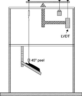
14.5 The schematic of the ADT shows the adhesive bond loaded at a 45 ° peel load. The sample sits in a water bath that is maintained at 37 °C.
Back to the thought experiment where the three different primers for a medical adhesive interface were evaluated against the control joint that contained no primer. In tensile, all primed bonds failed cohesively while the control joint failed adhesively. Such a test clearly establishes the control joint as inferior to the primed joints, but which of the other primers have the highest work of adhesion, the one that you want to use on your device joint? Loading bonds prepared with each of the primers into the ADT produces the results shown in Fig. 14.6.
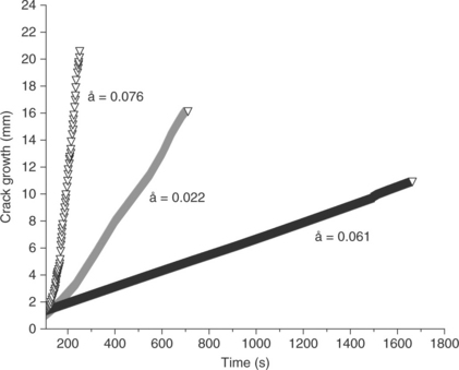
14.6 The ADT apparatus measures the crack growth rate, å, over time. Cracks at low energy interfaces propagate quickly, while cracks at high energy interfaces propagate slowly. This test method allows for differentiation of three primer systems that showed equivalency in a traditional tensile test due to a cohesive failure mode.
The slow rate of testing as well as the weak configuration of peel loading allows the primer systems to be ranked. In this case, the primer system represented by the black line propagates at a lower rate than either of the other primer systems tested under the same conditions. Therefore, the primer system represented in black produced the strongest bond. In all three cases, the bonds had adhesive failure, but they differ by orders of magnitude. This is in contrast to the cohesive failure mode of a traditional stress–strain test, where the cohesive failure mode masked this very large, and potentially critical, difference in the primer systems.
It can be difficult to evaluate different adhesive systems when the cohesive properties of the adhesive are changing. The real challenge is to find common testing conditions that will result in an adhesive failure mode for all the adhesives considered. In the case study below, two space-filling epoxy adhesives were being evaluated for their adhesive strength for a bond with titanium. Because the adhesive is a not flexible at the service conditions, the peel bond configuration could not be used. A tensile loading condition was chosen for the evaluation. Because it is important to measure the adhesive strength against substrates that represent the same mechanical finish as will be used in the device, titanium discs were punched from actual titanium devices. These discs were screened for flatness and cleaned as intended in the manufacturing process. The samples were built as shown in Fig. 14.7, where the adhesive was injected in a disposable cylindrical tube, the titanium disc was placed using an alignment tool to assure a perpendicular alignment, and then more adhesive was injected. The system was cured and the disposable cylindrical form was carefully removed from the test sample, where the test sample comprised the adhesive containing the titanium disc in the center. Finally, any adhesive was removed from the edge of the titanium disc before testing.

14.7 The tensile specimen used to test the adhesive bond between a stiff epoxy adhesive and a titanium disc. Such a joint design allowed for the epoxy to be evaluated against the actual titanium surface used in the medical devices.
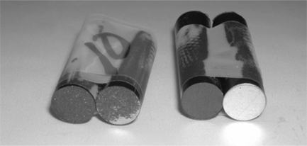
Testing was performed on the two epoxy systems as a function of strain rate. The test results are shown in Fig. 14.8. At all strain rates tested, one adhesive always failed cohesively – within the bulk of the adhesive. The other epoxy always failed adhesively, at the titanium interface. The failure modes of the two epoxy systems are shown in Fig. 14.9. Because the failure modes were different, the epoxy systems could not be evaluated comparatively. As described in Equation [14.2], the work of adhesion can be measured when the testing rate goes to zero. Extrapolating to zero rate for the epoxy system that failed adhesively gives a G0 = 16 lbs. The higher failure forces for the higher rate tests include the forces of the viscoelastic dissipation. The contribution of viscoelastic dissipation is represented by the shaded area in Fig. 14.8. The G0 was not measured for the system that failed cohesively because the crack did not propagate at the adhesive interface, but within the epoxy itself. New test conditions must be selected to evaluate G0 for this epoxy system. Slower test rates are required. The invariant load response of this system indicated that the cohesive properties were relatively unchanged within the testing rates explored. That is, the epoxy must be either on the rubbery plateau (above the glass-transition temperature (Tg) for the crosslinked system) or in the glassy regime (below Tg—see Section 14.2.3), as in both of these regimes the rate dependence is minimized. It is important to understand the viscoelastic properties of the adhesives in the joint being tested, as the rate of the joint test may change the load response of the joint considerably.
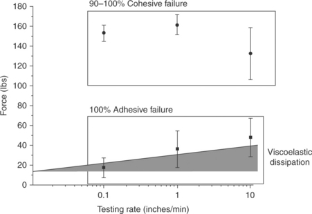
14.8 The force of failure is plotted as a function of testing rate for two epoxy systems bonded to titanium and subjected to tensile loading. One epoxy system failed cohesively and shows very little rate dependence (represented by the circles). The second epoxy, represented by the squares, failed adhesively. The failure load decreased with decreasing test rate. Extrapolation to a testing rate of zero gives G0 for the bond. The difference between G0 and the failure load is accounted for by the loads due to viscoelastic dissipation.
14.2.3 Viscoelasticity of polymers and adhesives
Polymers are viscoelastic because they have long chains that are highly entangled with each other.8 As a consequence, these long chains are not free to move without coordinating their motion with neighboring chains. The result is a time and temperature-dependent response to deformation. This response occurs both in the linear portion and the non-linear portion of the stress–strain curve. This rate effect is nicely demonstrated with Silly Putty®. If you pull Silly Putty® slowly, the chains have time to respond to the applied strain and they will flow by one another, failing cohesively at a relatively low force. At fast deformations, the chains remain entangled with their neighbors, and the applied load results in chain breakage. The failure mode is still cohesive but the failure force is higher than in the low-frequency test. Temperature can be a surrogate for frequency.9 At high temperatures, the chains have more mobility. Therefore, if strain is kept constant, and the temperature is high, the higher mobility of the chains will allow those chains to undergo coordinated motion and slide by one another, resulting in a low-force response. At cold temperatures, molecular motion is reduced and the mechanical response to the applied strain results in a higher force.
The time- and temperature-dependent response in the linear region of the stress–strain curve (at elongations below the yield point) is referred to as the linear viscoelasticity (LVE) of the polymeric material. A characteristic polymeric stress–strain curve is shown in Fig. 14.10a. The linear regime is highlighted at low strains. This regime is often characterized with dynamic mechanical analysis (DMA) to show how the response changes with either temperature or frequency. The resulting data, shown in Fig. 14.10b, is called the thermo-mechanical spectrum of the polymer or adhesive. The polymer or adhesive has a glassy region, the glass-transition temperature region, the rubber plateau and for non-crosslinked systems, a terminal flow region. Crosslinked adhesives have a rubber plateau that extends infinitely or until a temperature that results in thermal instability or degradation. This is because the chains are chemically bonded together in crosslinked systems, preventing flow. In other words, there are no temperatures or frequencies that will allow the chains to flow by one another.
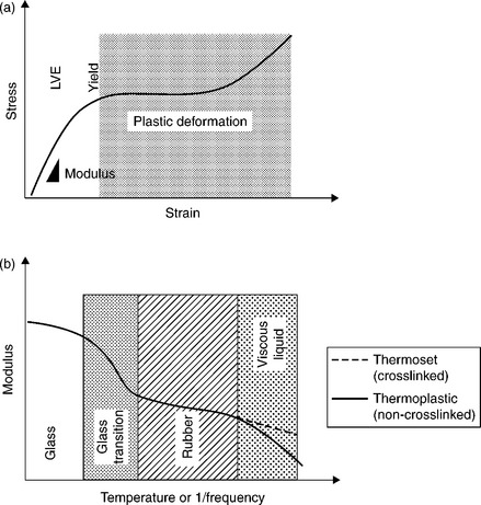
14.10 A typical stress–strain curve for a polymeric adhesive is shown in (a), where, like all polymeric materials, there is a linear portion, the slope of which is the Young’s modulus, a yield region, and a plastic deformation region. Because polymeric materials comprise long molecules that require coordinated motion, their response to an applied load is both temperature and frequency dependent. The temperature–frequency relationship of the linear region (LVE) can be characterized by DMA as shown in (b). Polymeric materials can either be a glass, if the temperature of service is below the glass-transition region, or they can be rubbery, if the temperature of service is above the glass-transition temperature.
Note: for those familiar with DMA, recall that DMA measures the elastic modulus rather than the Young’s modulus. For the purpose of this chapter these moduli are used interchangeably. The reason being, that the Young’s modulus and the elastic modulus only differ slightly in the transition region. The two moduli are compared in Fig. 14.11.
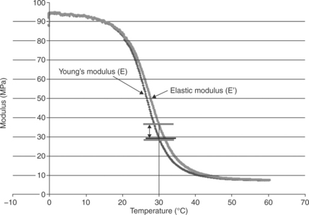
14.11 For practical assessments, the Young’s modulus and the elastic modulus can be used interchangeably. The two values differ slightly in the glass transition region.
An understanding of the service conditions with respect to the thermomechanical response of the adhesive is critically important to predicting the properties of the adhesive joint. If the service conditions result in the adhesive being in the glassy region, the slope of modulus with respect to either frequency or temperature is shallow. A similar shallow slope exists for adhesives in operating in their rubbery zone. In these regions, the cohesive failure loads will have only slight dependence on temperature or frequency. However, if service conditions put the adhesive in its glass-transition zone, the properties of the joint can change dramatically with changes in testing frequency or temperature. This can make accelerated testing designs problematic.
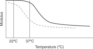
A crosslinked epoxy is used to adhere the electronic module assembly and the battery to the inside of the titanium shields of an implantable pacemaker. The electronic module assembly and the battery communicate through a series of wires. Flexing of the titanium shields puts fatigue forces on the wire, which can result in fatigue failure of the wire if the load or the number of cycles becomes high. The epoxy has two purposes: to provide stiffness and to provide high adhesion strength. Two different adhesives were considered for the application. Let us do the following thought experiment: We tested the bond stiffness and adhesion strength of the two epoxy systems at room temperature (22 °C). The performance of these epoxies was indistinguishable. The thermo-mechanical spectra of these epoxies is shown in Fig. 14.12. Which epoxy will perform the stiffness function at the service conditions of body temperature (37 °C)? The epoxy represented by the black line in Fig. 14.12 will be considerably stiffer than the epoxy represented by the dashed line at body temperature. This is the reason that it is important to understand the thermo-mechanical spectrum of the adhesive being considered. Furthermore, testing the adhesive at body temperature becomes critically important when designing a system with a glass transition temperature near the service temperature. Matching the exact temperature or frequency conditions of service becomes less critical when the adhesive system is being used at conditions away from the transition region as the modulus/temperature/frequency relationships are weaker in these regions.
14.2.4 Accelerated testing of adhesive joints
Before designing an accelerated test strategy, one must evaluate how the joint will fail in service.10 Remember, it is important to match the failure mode of the joint test to that anticipated in service to learn anything about that joint performance in service. In vivo, adhesive joints can fail due to excessive loads, in cyclic flex or fatigue loading, due to swelling of the adhesive or substrate, due to thermal shock, or fail through chemical degradation. For the purpose of this chapter, let us assume that we have chosen a biostable adhesive that does not chemically degrade during the timeframe of use. In which case, we have the possibility of mechanical failure at the interface (adhesive) or within the adhesive itself (cohesive) due to overload, fatigue, swelling, or thermal shock. There is also an additional failure possibility, chemical failure at the interface. However, you will learn in the next section that the creation of a chemical bond at the interface is a special case that must be engineered explicitly. Due to the limited material choices for medical devices, there is rarely the material flexibility to engineer chemical interfacial bonds. As a consequence, most bonds are mechanical in nature, not chemical.
Often in the medical-device industry, we refer to ASTM F1980–02, Standard Guide for Accelerated Aging of Sterile Medical Device Packages, to design our accelerated tests. This test references the Arrhenius equation, where van ’t Hoff’s observation is applied, as shown in Equation [14.3]. This principle was established by observing that the reaction rate of rate of gas molecules roughly doubles for every 10 °C increase in reaction temperature. This method teaches that a material held at a temperature higher than the service temperature will age via chemical reaction faster than it will at the service temperature. A shorter time at a high temperature will simulate a longer time at the service temperature. Therefore, if a material passes a simulated lifetime age according to the Arrhenius equations and results in a favorable outcome, the polymeric system should survive its anticipated service life.
where TimeAccelerated = time the sample is exposed to achieve a desired shelf time; TimeRoom temp = desired shelf time; Q10 = 2, aging factor for a 10 °C increase or decrease in temperature (van’t Hoff’s observation: the rate of chemical reactions double with every 10 °C increase in temperature); Tacc = accelerated aging temperature (°C); TRT = room/ambient temperature for storage (°C).
Not so fast for adhesive bonds! The Arrhenius equation is an empirical relationship that was established for the prediction of chemical reactions. Chemical bonds are rarely responsible for the forces holding an interface together. The most common cause of adhesive failure is a stress discontinuity at the interface that results in the propagation of a crack at that interface. The stress discontinuity can result from (i) a modulus discontinuity between the substrate and the adhesive where an applied load (or repeated cyclic load) results in an interfacial stress riser; (ii) preferential swelling of the adhesive or substrate by body fluids that result in expansion of the adhesive or substrate, imparting a stress riser at the interface; and (iii) thermal cycling or shock of a joint comprising materials with different coefficients of thermal expansion.
With this in mind factors that accelerate the decay of an adhesive bond include temperature cycling, constant loading (creep), cyclic loading and humidity/environment. Often the combination of more than one of these factors is substantially more severe than any of the factors alone.11 When designing an accelerated test strategy for the joint in question, apply the combination of factors that best simulate the anticipated service conditions of the joint. For example, in the automotive industry, joints are accelerated aged by applying a constant load (creep), cycling the joints through a salt solution daily, and storing in a humidity cabinet at elevated temperature and humidity. Time to failure is recorded and the results are compared with real-time testing to establish an acceleration factor. It is clear that this accelerated test was designed with all of the possible environmental assaults incorporated in addition to extreme temperature, humidity and loading conditions to produce an accelerated failure model.
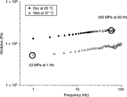
A solvent bond in a polyurethane lead body (long polymeric tubes containing the metallic conductors that carry the energy from the pacemaker to the heart) was tested at accelerated flex fatigue conditions. The joint was testing at extreme curvature and at a fast frequency (60 Hz) to the total number of life cycles anticipated in the actual application. This test was run dry and at room temperature. The actual application would have a flex frequency of about 1 Hz (the rate of a beating heart), would be saturated with blood, and would be at 37 °C body temperature. Understanding the thermo-mechanical spectrum of the joint in the two different test conditions gives an appreciation of the extreme nature of the accelerated test. The thermo-mechanical spectrum is shown in Fig. 14.13. The load generated at the solvent bond in the polyurethane lead body was four times greater in the accelerated test (60 Hz, dry, room temperature) than the load expected in vivo (1 Hz, wet, body temperature). The higher loads generated at the accelerated conditions will accelerate failure. The acceleration factor must be established with real-time/condition testing to failure.
14.3 Mechanisms of adhesion
This section will discuss basic mechanisms of adhesion, specifically forces that act across the interface between medical-device components to be bonded or between the adhesive and the substrates. Because these forces act at a molecular or atomic scale across the interface, intimate contact between the adhesive and the substrate is needed in order to benefit from these mechanisms. Practically, these forces can be loosely grouped into several categories: mechanical, intermolecular (van der Waals), and primary (covalent) forces.12–14 An adhesive bond may rely on more than one mechanism to achieve full bond strength.
Mechanical forces: The mechanical mechanism relies on the adhesive to fill crevices and voids of substrate surfaces to create an interlocking structure. This composite structure ideally has the mechanical strength of the weakest component of the system, therefore, the bulk strength of the substrate or adhesive. Because of this, bonds that rely on mechanical interlocking can be quite strong. This mechanism is the most common and the easiest to implement. Roughening a smooth surface with sandpaper before painting is an example of using mechanical interlocking to improve adhesion.
Two conditions need to be met in order to maximize mechanical interlocking: the substrate surface should be rough and the adhesive must flow into this microscopic topography and ‘wet out’ the surface. Without intimate contact, voids will form in the adhesive/substrate interphase and the joint strength will be reduced. The concept of wetting of the adhesive on the substrate will be discussed in a later section. In addition to creating texture for mechanical interlocking, roughening the surface also increases the substrate surface area on a microscopic scale. If the adhesive is in intimate contact with the substrate, this allows for more opportunities for primary or inter-molecular forces to act across the interface; the joint surface has more area for chemical bonding. Practically, since adhesion is measured as the force required to pull a joint apart per bonded area, increasing surface area on a microscopic scale increases the apparent adhesion.
Intermolecular forces: Intermolecular forces, or van der Waals forces, act between molecules and do not involve the formation of covalent bonds. Electrons are not permanently shared in this type of bond. Therefore, intermolecular forces are relatively weak compared with covalent bonding. Van der Waals forces arise from several different types of interactions of localized areas of charge on molecules (dipoles):
• Electrostatic interactions between permanent dipoles: These dipole– dipole interactions involve the transient attractive forces of two oppositely charged dipoles. Hydrogen bonding within water is a very common example of this. The electronegative oxygen of one H2O molecule is attracted to the electropositive hydrogen of another H2O molecule. In hydrogen bonding the dipoles, or the electronegative or positive nature of parts of the water molecule, are permanent, but the intermolecular interactions between these dipoles are not.
• Induced dipole–permanent dipole interactions: In this case one of the dipoles is induced by its environment and interacts with a permanent dipole. The induced dipole is a localization of molecules electron cloud and transient in nature.
• London dispersion forces: These are weak interactions between multiple-induced dipole forces.
Although van der Waals forces are weak compared with covalent bonds, they are very common and contribute to the bond strength of many adhesive joints. These bonds are prevalent because they do not require a specific chemistry to form, simply oppositely charged dipoles. However, because van der Waals forces act on a molecular and atomic scale, intimate contact between molecules of the adhesive and of the substrates is essential for this type of bonding to occur. Hydrogen bonding between electropositive areas of polymers chains or adhesive molecules and electronegative metal oxides on the surface of many metals is a common example of intermolecular forces used in adhesive joints.
Primary forces: In this mechanism covalent bonds are formed across the interface; electrons are shared between atoms and permanent chemical bonds are created. Covalent bonds are very strong and, when achieved in an adhesive joint, result in strongly bonded components or coatings. Since these primary forces act on an atomic scale intimate contact between the adhesive and the substrate is necessary; the adhesive must wet and spread on the substrate. Additionally, reactive species in the adhesive must come within Angstroms of the corresponding reactants on the joint surface. The adhesive itself is composed of many components, only some of which are responsible for bonding to the substrate. Therefore, mobility of chemical species within the adhesive is an important consideration in creating covalent bonds across the interface of an adhesive joint. This mechanism is the least prevalent bonding mechanism and is the most difficult to achieve.
Entanglements: The utilization of entanglement across the interface is considered a special case adhesion mechanism. That is, this mechanism of adhesion does not occur by accident, but must be engineered into the system. To create a bond that takes advantage of interfacial entanglements requires three things: (1) the thermodynamic compatibility of the materials being joined such that an interphase can be created; (2) enough chain mobility (through the application of heat or the introduction of a solvent) that allows the chains to entangle within the interphase; (3) the chains that entangle must be long enough to form mechanically sufficient entanglements—otherwise the entangled chains have no strength and act as interfacial contaminates that impede bond strength.15 The interfacial entanglement mechanism is drawn pictorially in Fig. 14.14. A well-designed adhesive bond takes advantage of multiple mechanisms of adhesion.

14.14 Diagram showing interfacial entanglements that can occur when the two materials in close contact have the thermodynamic compatibility that creates an interphase that allows for the incorporation of entanglements. These entanglements only will produce an interface capable of withstanding mechanical loading if the interfacial entangled chains are well anchored into the bulk structure.
14.3.1 Wettability and surface energy
Wettability of the adhesive on the substrates of an adhesive joint is an important consideration in designing component bonds in medical devices.16 In order to take advantage of the mechanisms discussed in the previous section, the adhesive must completely cover the substrate, fill microscopic crevices and not bead up. The adhesive should be in intimate contact or wet the substrate. Wettability is driven by the surface energy (γ) of the liquid adhesive with respect to the substrate. For good wetting the surface energy of the substrate should be greater than the surface energy (or surface tension) of the adhesive. For poor wetting the surface energy of the substrate is less than the surface energy of the adhesive. The thermodynamic tendency to decrease the energy of the system is the driving force for wetting. In general terms, a low energy adhesive readily will wet and cover a high-energy substrate surface because the overall energy of the system is reduced. Conversely, a liquid adhesive will bead up on a substrate with a lower surface energy. For example, most liquids will bead up on a low energy fluorocarbon surface, such as the Teflon surface of a sauté pan. No thermodynamic advantage is gained by the higher energy liquid spreading on the lower energy Teflon pan.
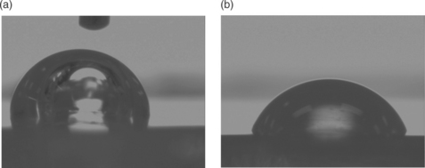
Surface energies or surface tension can be measured by examining contact angles. The contact angle is defined by solid surface and a line drawn tangent to the curve of a drop of liquid where the liquid touches the solid. This is shown below in Fig. 14.15.
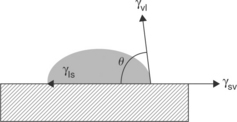
Equation [14.4], the Young Equation, describes the system of a drop of a liquid sitting on a surface with the solid–vapor, solid–liquid and vapor–liquid interfaces in equilibrium.17 Contact angle goniometers and dynamic contact angle analyzers use these principles to routinely measure contact angles. Additionally, specially prepared pens and dyes can be placed on a surface for a comparative assessment of surface energy.
where θ is the contact angle; γsv = solid–vapor; γsl = solid–liquid; γvl = vapor–liquid.
In adhesion discussions, water contact angles are often used to describe the surface state of solid materials. Surfaces which are completely wet by water are called hydrophilic. Surfaces on which water beads up are called hydrophobic. In very general terms, it is difficult to bond to hydrophobic surfaces. The hydrophobic nature of the surface impedes spreading of most adhesive chemistries and may also indicate that the surface is contaminated with waxes, grease, processing aids, silicone oils, etc. These contaminants have low surface tensions and readily spread on many solids. A contamination layer will result in poor adhesion unless removed. Water contact angles can be used to assess the cleanliness of surfaces to be bonded. For example, the surfaces of polyurethane components are often contaminated with waxy processing aids. This polyurethane material is shown on the top of the device picture in Fig. 14.3. Changes in the water contact angle can indicate the effectiveness of cleaning. This is illustrated in Fig. 14.16. The contact angle of a drop of water on the surface of an uncleaned polyurethane connector module is 103 °, whereas the contact angle on an effectively cleaned connector module is 70 °.
14.3.2 Hydrophobic recovery
Contact angle measurements are able to detect contaminants and changes in surface chemistry that are generally only visible with sophisticated surface analysis techniques such as x-ray photoelectron spectroscopy (XPS) and time of flight secondary ion mass spectrometry (ToF SIMS).18 This information is important because even very low levels of contamination or small changes in the surface chemistry can impact adhesive bond strength. These changes can take place during storage after a device has been cleaned, but before bonding.
The thermodynamic forces that govern wetting behavior also drive adsorption of volatile contaminants or the diffusion of mobile additives in a polymeric resin. Volatile hydrocarbon or silicone contamination from the manufacturing or laboratory atmosphere can readily adsorb onto high surface energy substrates. Mobile components (processing aids, unreacted monomer, waxes, etc.) of polymers can diffuse to surfaces and form weak boundary layers. Additionally, the orientation of hydrophobic sections of a polymer chain can reorient to the polymer surface and reduce surface energy. This phenomenon is called hydrophobic recovery.19–23 The example described below and shown in Fig. 14.17 illustrates the reversion of a hydrophilic surface to a more hydrophobic surface.24

14.17 Graph depicting water contact angles (left axis) and oxygen/carbon (O/C) ratios measured by XPS (right axis) for siloxane primer films with and without an oxygen plasma post-treatment.
Siloxane coatings deposited from reactive gas plasmas are hydrophobic with water contact angles measured at approximately 100 ° (open circles in Fig. 14.17). During storage in a petri dish in a laboratory environment, the surface is stable over 150 hours with little change in the water contact angle or oxygen to carbon ratio measured by XPS (filled circles). Treating this siloxane surface with an oxygen gas plasma changes the surface chemistry and energy. Immediately after treatment the surface is completely wet-table and the water contact angle is zero (open squares). However, over the course of 2 days the surface recovers some of its hydrophobic nature. The water contact angle increases to approximately 40 ° and the oxygen to carbon ratio drops from approximately 9.7 to 6.6 (filled squares).24 This example illustrates the need to bond an adhesive joint as soon as possible after substrate cleaning or pre-treatment.
The concepts of wettability and surface energy can be applied practically when choosing materials for an adhesive joint. An adhesive/substrate combination should be chosen in which the adhesive will readily wet the substrate surface enabling mechanical interlocking, van der Waals bonding or covalent bonding. That is, an adhesive should be chosen with a surface tension equal to or less than the surface energy of the substrate in order to achieve this wetting and intimate contact. Additionally, water contact angles can be used to test the cleanliness of medical device components and the effectiveness of surface pretreatments that modify surface chemistry.
14.3.3 Weak boundary layers
Weak boundary layers, which can impede adhesion, are found at the interface between the adhesive and the substrate.25 Many different materials can function as a weak boundary layer. As discussed in the previous section, contaminants, processing oils, waxes, detergent residue, brittle or water soluble oxide layers and adsorbed water can all act as weak boundary layers. These materials displace the adhesive from the substrate surface, intercept potential bonding sites, and, in the case of adsorbed liquids can plasticize the adhesive making it soft. This softening may create a stress discontinuity at the interface and weaken the joint. Weak boundary layers on joint components should be removed before bonding. It is imperative to understand the timeframe in which weak boundary layers can reform. If possible, it is ideal to perform the bonding process immediately following substrate pre-treatment.
14.4 Adhesion promotion
In addition to optimizing joint design and choosing an appropriate adhesive, the strength and durability of an adhesive joint can be improved by cleaning and modifying the substrate surfaces.26 The goals of surface treatments are to remove weak boundary layers, promote intimate contact, increase wettability of the adhesive on the substrates and provide a surface chemistry that can react with both components of the joint – the substrate and the adhesive. A variety of mechanical, wet chemical and vacuum processes can be used to achieve these goals. Surface treatments often have multiple effects on the morphology and chemistry of the substrate surface. It is important to be aware of unintended consequences and, as discussed in a previous section, bond the adhesive joint as soon after cleaning or surface treatment as possible.
Roughening the surface: Roughening the surface of substrates creates surface features that can be filled with adhesive, thus promoting mechanical interlocking. Additionally, roughening increases surface area and potential sites for intermolecular and covalent bonding. Removing material from the surface can also aid in cleaning by removing contamination, however, care should be taken to remove all debris which could serve to create a weak boundary layer.
Metal and polymer surfaces can be roughened mechanically with abrasives such as sand paper, by grit or bead blasting, water jet profiling, etc. These processes can alter surface morphology on the microscopic to visible scale. Substrates surfaces can also be roughened by chemical means. Acid and basic solutions can be used to etch and create texture on metal, and in some cases, polymer surfaces. For example, aqua regia solutions of nitric and hydrochloric acid can be used to etch platinum/iridium alloys used in medical devices. The disposal of spent etching solutions often makes the use of this technique unattractive. It is also possible to use vacuum or atmospheric plasma processes to roughen substrate surfaces on a microscopic scale. These can be physical processes, such as argon sputtering, or chemical processes involving reactive gas plasmas. It should be noted that these wet and vacuum chemical processes leave behind etch residues that can be detrimental to adhesion. It is necessary to understand the potential of creating etch residues and develop procedures to remove or neutralize them.
Cleaning: Numerous procedures and materials have been developed to remove contaminants from surfaces. It is useful to understand the contaminants in the component manufacturing process in order to choose the best cleaning procedures. Detergent solutions (e.g., Micro 90, LiquiNox, etc.) target multiple types of contaminants such as oil, grease, flux, particulates, hard water stains and biological debris. Solvents have long been used to remove waxes, mold release agents and oils present on component polymer surfaces, however, new green manufacturing processes continue to be implemented. Super critical CO2 processes have been implemented successfully for solvent free cleaning of medical device components. Additionally, many of the processes discussed in the previous section (wet chemical etching, plasma and vacuum processes) will remove contamination, in addition to roughening the surface.
Cleaning can often be facilitated by the addition of energy to the cleaning bath. Heat increases solubility of contaminants in the cleaning solution. Stirring and the use of an ultrasonic bath will also improve cleaning effectiveness by moving contaminants away from the components. Adequate rinsing is a critical part of cleaning that is often overlooked. In a cleaning bath contaminants are removed from the component, but can redeposit onto the surface. Rinsing helps to manage this re-deposition. Understanding the contaminant load of the cleaning bath and changing the solutions accordingly can reduce the re-deposition of contaminants. Additionally, cleaning should not negatively affect the bulk properties of the component. For example, acetone used as a cleaning solvent can induce crazing in polysulfone that has been molded with high residual stress.
In choosing a cleaning process it is important to consider the potential contaminants, the effectiveness of the cleaning method, the level of cleanliness needed for adhesion and the effect on the bulk properties or functionality of the component.
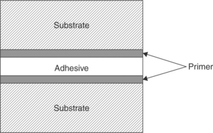
Primers: Primer films or coupling agents (shown in Fig. 14.18) are used as a bridging layer between the substrate and the adhesive.27 It is important for a primer to be well adhered to both the substrate and the adhesive or it becomes a weak boundary layer. Primers, when chosen wisely, can promote intimate contact, improve wetting of the adhesive on the surface and alter the chemistry of the substrate surface to suit the adhesive and promote chemical bonding or an entangled interphase.
Primers can be grouped into different categories: reactive and entanglement primers. Silane coupling agents are a very common reactive primers used to promote adhesion between metal or glass and polymeric adhesives,28 shown in Fig. 14.19. These primers consist of alkoxy groups that hydrolyze to Si-OH and then bond to the substrate and an organic tail containing a functional group (X) that is compatible with the adhesive. Amine, epoxy and vinyl functional silane primers are common. These primers are usually applied as dilute solutions in water or alcohol. Care must be taken as excess primer on the adherend surface acts as a weak boundary layer. This is often observable as a fine white residue.
Entanglement primers are used to promote wetting and the entanglements of polymer chains from the adhesive. They may simply be adhesive dissolved in a solvent. The low viscosity of these primers allows them to spread more readily over the substrate surface. Because they are chemically similar to the adhesive, chain entanglement is favored.
Primer films can be deposited using a variety of application methods such as dip coating, spin coating, electrostatic spray coating, vacuum or plasma deposition, or with a brush. Plasma deposition merits special consideration because the excited, high-energy state of a plasma can readily promote adhesion of the depositing primer to the substrate without having to follow typical chemistry rules. The best application method will depend on the primer itself and on the part geometry.
14.5 Types of adhesives used in medical devices
There are different requirements for adhesives used in short-term, disposable devices that have little to no blood contact, compared with those used in long-term implantable devices that are tissue and blood contacting. In the latter case, stringent criteria for leachables, stability and toxicity restrict adhesive options. In contrast, short-term use materials do not require the long-term stability in the harsh environment of the human body. Adhesive degradation such as hydrolysis and oxidation are typically not considered in disposable medical-device products. Also, some adhesives produce extractable or leachable products, whether through degradation or from additives and synthesis residuals, that are harmful to surrounding tissue. These materials should not be used in long-term implantable devices, but often are found in medical devices that are short-term, non-implanted use.
Adhesives can be space-filling or non-space-filling. In space-filling applications, the adhesive itself needs to have both cohesive strength and adhesive strength to support the design loading conditions. In a non-space-filling application, the adhesive can be a thin coating that is applied to the joint to facilitate either a thermal-bonding process or a solvent-bonding process. Adhesives can be one-part or two-part systems. In a one-part system, the resin and the cure agent/crosslinker/catalyst are supplied in a single cartridge. The chemistry of the adhesive system is designed such that the cure agent cannot undergo reaction at the cartridge storage conditions prior to use. The reaction of these systems is initiated by some outside condition such as moisture, heat, or acid. Exposure to the conditions required for curing initiates the cure agent and the reaction proceeds. In two-part adhesive systems, the resin and catalyst are supplied in two separate cartridges. Mixing occurs at the time of use and cure proceeds upon contact if the two components are properly blended. Working times for the two-part systems are reduced for fast-curing systems.
The main adhesive chemistries used for long-term implantable medical devices are polyurethanes, silicones and epoxies. Polyurethanes and silicones are also used as medical-device materials, as they are known to be stable when implanted in the body. Silicones adhesives (sealants) are space filling and can be one-part RTV (room temperature vulcanized) or two-part systems. The RTVs are a moisture-activated system that upon curing evolves acetic acid, methanol, or oxime, depending on the chemistry. Because the RTV systems are moisture cured (water must diffuse into the structure and acetic acid must be liberated), the use of these adhesives is restricted to shallow bondlines that tend to have large surface areas. An example of such an application is shown in Fig. 14.20, where the feedthrough wires on the pacemaker are covered with the RTV to protect the metal components from the body salts that could result in corrosion. In this case, the RTV must form a durable and reliable bond with a number of different substrates that include polyurethane, epoxy, titanium, stainless steel and MP35N alloy. The cure of RTVs is accelerated by increasing the humidity. A common mistake is to try to accelerate the cure of these materials by placing the joint assembly into an oven. Because hot air has reduced water capacity, the cure rate for these moisture-cured systems may be reduced.
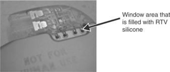
14.20 RTV silicone is dispensed onto device and prevents fluid ingress into electrical components. Joints designed with RTVs must be shallow and have a large surface area to facilitate the water and acetic acid diffusion that is required for cure.
Two-part silicones are typically mixed in equal parts and use a platinum catalyst to facilitate the crosslinking reaction. These materials will cure at room temperature, but can be accelerated with increasing temperature. Caution should be used as changing the cure path of an adhesive may alter the adhesion strength or the cohesive properties of the adhesive. Unlike RTVs, these adhesive can be used in enclosed joints of undetermined thickness, because the cure mechanism relies on heat, not on the diffusional transport of water and acetic acid.
Epoxy adhesives are space filling and can be either one- or two-part. Because one-part systems generally require a high temperature or other external factors to initiate the cure, two-part systems are often used for joints that are hidden and/or cannot withstand large temperature excursions. For example, medical devices that contain electronics and batteries cannot withstand large thermal excursions. Therefore, pacemakers that contain such electronics and batteries generally utilize two-part systems. One such two-part system is used to adhere the battery and the electronic module assembly to the titanium can of the pacemaker, as shown in Fig. 14.21. This is the same adhesive system that was used in the example depicted in Fig. 14.12. In the pacemaker application, a second titanium shield is welded to the first after bonding of the internal components. The result is a hermetically sealed device that does not come into contact with the biological environment; therefore this adhesive system is non-body contacting.

14.21 Epoxy dispensing pattern on the inside of pacemaker titanium shield. The battery and the hybrid/electronic modulus assembly are placed on the adhesive and the assembly cures at room temperature.
Solvent welding/bonding is often used to seamlessly bond similar materials to each other. This type of bonding strategy is used for non-space filling applications, between two materials that are thermodynamically compatible and in intimate contact. For example, two different polyurethanes, having different durometers such as 55D and 80A, are often joined along a catheter, resulting in a device that has variable stiffness along the length. The solvent is introduced at the interface that is in intimate contact. The solvent lowers the glass-transition temperature of the polymer upon contact. The affected chains become mobile. The increased mobility of polymer chains on both sides of the interface result in interfacial entanglements if, and only if, the polymers sitting at the interface are miscible or thermodynamically compatible and the two materials sitting at the interface are in contact. A strong bond forms if the chains form adequate interfacial entanglements (driven by the solvent compatibility and solvent volume applied) and when the solvent is completely removed from the bond after the entanglement occurs. Interfacial contaminates (weak boundary layers) such as additives in the polymer that aid in extrusion (wax) can impede adequate bond formation if not removed from the surface before bonding.
Pressure sensitive adhesives (PSAs) are an assembly aid in the construction of medical devices. PSAs are generally considered to be non-space filling and most are non-reactive. These materials are usually supplied as tapes of varying thickness. For a PSA to work, the adhesive must flow into the rough surface features of the substrate. This takes time and pressure, parameters specified by the manufacturer in the technical data sheet. Because the PSA must be a flowable system to create bond, the PSA has the ability to flow after the bond is created, when the device is in service. This necessitates that the PSA attached components be secured by an additional mechanism. Mechanical stops have been utilized in combination with PSAs to prevent movement of components. Alternately, a supplemental addition of a curable, space filling adhesive system might be used to secure the components in the final assembly step.
The main adhesives used for short-term non-implantable medical devices are materials that are inexpensive and cure fast. These include cyanoacrylates and light curable materials. Cyanoacrylates, a.k.a. SuperGlue™, are widely available in different chemistries for multiple substrates, and can be offered in low- to high-viscosity formulations. These are one component adhesive systems that are limited to thin bond lines or non-space filling applications. Cyanoacrylate formulations have an acidic stabilizer that prevents the adhesive molecules from reacting in the tube. When applied, low levels of moisture on the substrate surface neutralize the acid stabilizer, initiating anionic polymerization of linear polymer chains, from the surface into the bulk. The interpenetrating nature of the acrylate polymer created is responsible for the joint strength. Cyanoacrylates are not used for long-term body-contacting medical-device applications because this chemistry is not hydrolytically stable and will eventually bio-resorb. However, this attribute makes cyanoacrylate chemistry perfect for wound-closure applications.
Light curable adhesives are the fastest curing adhesives, sometimes curing in a matter of seconds. These adhesives contain a photo initiator that when exposed to light, most often UV light, initiate a free radical or cationic reaction. When the light source is removed, the free radical cure schemes stop, while formulations with cationic chemistry continue to react. While widely used in non-implanted medical devices, these are not used in body-contacting long-term implants due to the toxicity of the photo initiators currently available. To use a light curable adhesive, the entire joint must be accessible by the light source. Adhesive, buried in joints that cannot be exposed to the light beam, will not cure, a phenomenon known as ‘shadowing’. This limits the joints to clear materials with good UV transmission, or simple joint designs. To combat this issue dual cure formulations have been developed that offer the quick curing using light sources, and then offer a secondary cure mechanism for the shadowed areas, either by moisture or heat.
14.6 Conclusion
Joint design is the single most important factor in determining the overall joint strength. Joint designs must be created to minimize peel- or cleavage-loading conditions. When joints fail, they can fail adhesively, along the interface, cohesively, within the bulk of the adhesive, within the substrate, or in a complex manner that can result in a wandering crack. If the failure strength of the joint is not adequate for the application, then joint re-design should be the first consideration. At the small lengths scales required in medical devices, often joint re-design is a difficult option to consider. In those cases, one might be able to improve joint strength by understanding the failure mode of the joint and implementing improvements to that part of the system. Of critical importance is to assure that the failure mode observed in the in vitro evaluation of the joint matches that anticipated or observed in vivo. If the failure mode is cohesive, within the adhesive material, strategies to improve the biostability and/or the bulk strength of the adhesive must be employed. More often than not, the in vivo environment produces an adhesive failure mode. The interfacial interactions can be improved to increase the adhesion strength of the joint. These interfacial interactions include modifying the mechanical roughness features of the substrate, improving substrate-adhesive wettability, implementing primers to harness covalent interfacial interactions, eliminating weak boundary layers through better cleaning methods, and enhancing interfacial entanglements in systems compatible with this approach.
There are a limited number of adhesive chemistries available for use in medical devices because of performance in the body and toxicity considerations. The adhesive options are even further restricted for use in long-term tissue and blood-contacting applications. Long-term implant adhesive options tend to focus on silicones and epoxies. In addition, PSAs (isolated from body tissue) are sometimes employed in combination with other stabilizing strategies due to the flow properties of the non-reactive PSA systems. Disposable medical devices tend to use fast-cure systems such as cyanoacrylate and UV curable systems. The adhesive selection process must take into account the substrate chemistry, the bulk strength requirements for the adhesive, the adhesive strength requirements of the interface, the environmental conditions during device usage, any manufacturing constraints like cycle times, and any thermal excursion constraints of the device or component containing the joint. One component adhesive systems require some external condition to initiate cure such as heat. These systems have the advantage of long working times for adhesive application. Two component systems begin to cure upon mixing, where the degree of mixing and the metering of each component is critical to the final adhesive properties. These materials have short working times, as the viscosity begins increasing at the point of mixing. However, these systems offer the advantage of a room-temperature cure, often a critical criteria for medical devices that have temperature excursion limitations due to the incorporation of batteries.
14.7 Sources of further information and advice
Lee Lieng-Huang, ed. Fundamentals of Adhesion. Plenum Press, 1991.
Lee Lieng-Huang, ed. Adhesive Bonding. Plenum Press, 1991.
Pocius, A.V.Adhesion and Adhesive Technology: An Introduction. Hanser Gardner Publications, 1997.
Petrie, Edward M.Handbook of Adhesives and Sealants. McGraw-Hill Professional, 1999.
Kinloch, A.J.Adhesion and Adhesives: Science and Technology. Chapman & Hall, 1987.
14.8 References
1. Petrie, E.M.Handbook of Adhesives and Sealants. New York: McGraw Hill, 2000.
2. Kline, R.A. Stress analysis of adhesively bonded joints. In: Mittal K.L., ed. Adhesive Joints: Formation, Characteristics, and Testing. New York: Plenum Press; 1984:587–610.
3. Kinloch, A.J., Moore, D.R. The influence of adhesive bond line thickness on the toughness of adhesive joints. In: Moore D.R., ed. The Application of Fracture Mechanics to Polymers, Adhesives and Composites. Kidlington, Oxford, GB: Elsevier; 2004:149–155.
4. Chastian, C.E. Designing adhesive joints. Appliance Engineer. 1974; vol. 8(4):22–25.
5. Ahagon, A., Gent, A.N. Effect of interfacial bonding on the strength of adhesion. Journal of Polymer Science, Polymer Physics. 1975; vol. 13:1285–1300.
6. Chun, H. and Gent, A. N., ‘Effect of length and number of interlinking molecules on the strength of adhesion’, Journal of Polymer Science, Part B: Polymer Physics, vol. 34, no. 13, pp. 2222–2229.
7. Shepard, N.E., Wightman, J.P. A simple device for measuring adhesive failure in sealant joints. In: Klosowski Jerome M., ed. Science and Technology of Building Seals, Sealants, and Weatherproofing: Seventh Volume ASTM STP1334. West Conshohocken, PA: American Society for Testing and Materials; 1998:78–86.
8. Young, R.J., Lovell, P.A.Introduction of Polymers: Second Edition. New York: Chapman & Hall, 1991.
9. Macosko, C.W.Rheology Principles, Measurements, and Applications. New York: VCH Publishers, 1994.
10. Nelson, W.Accelerated Testing. New York: Wiley, 1990.
11. Dickie, R.A., Debolt, M.A., Ward, S.M.Stress Durability Testing of Adhesively Bonded Steel. Warrendale, PA: SAE 950128 Society of Automotive Engineers, Inc., 1995.
12. Pocius, A.V. Adhesion and Adhesives Technology: An Introduction, 2nd. Hanser Gardner Publications, 2002.
13. Comyn, J. What are adhesives and sealants and how do they work. In: Adams R.D., ed. Adhesive Bonding Science, Technology and Applications. Cambridge: Woodhead Publishing; 2000:41–51.
14. Baier, R.E., Shafrin, E.G., Zisman, W.A. Adhesion: mechanisms that assist or impede it. Science. 1968; vol. 162:1360–1368.
15. Chaffin, K.A., Knutsen, J.S., Brant, P., Bates, F.S. High-strength welds in metallocene polypropylene/polyethylene laminates. Science. 2000; vol. 288:2187–2190.
16. Kinloch, A.J. Adhesion and Adhesives: Science and Technology. London: Chapman & Hall, 1987; 18–55.
17. Schrader, M.E. High and medium energy surfaces: ultrahigh vacuum approach. In: Schrader M.E., Loeb G.I., eds. Modern Approaches to Wettability Theory and Applications. New York: Plenum Press; 1992:54.
18. Watts, J.F. Surfaces: how to assess. In: Adams R.D., ed. Adhesive Bonding Science, Technology and Applications. Cambridge: Woodhead Publishing; 2000:52–74.
19. Fritz, J.L., Owen, M.J. Hydrophobic recovery of plasma-treated polydim-ethylsiloxane. Journal of Adhesion. 1995; vol. 54:33–45.
20. Everaert, E.P., Vander Mei, H.C., Devries, H.J., Busscher, H.J. Hydrophobic recovery of repeatedly plasma-treated silicone rubber 1. Storage in air. Journal of Adhesion Science and Technology. 1995; vol. 9:1263–1278.
21. Everaert, E.P., VanderMei, H.C., Busscher, H.J. Hydrophobic recovery of repeatedly plasma-treated silicone rubber 2: a comparison of hydrophobic recovery in air, water, or liquid nitrogen. Journal of Adhesion Science and Technology. 1996; vol. 10:351–359.
22. Owen, M.J., Smith, P.J. Plasma treatment of polydimethylsiloxane. Journal of Adhesion Science and Technology. 1994; vol. 8:1063–1075.
23. Morra, M., Occhiello, E., Marola, R., Garbassi, F., Humphrey, P., Johnson, D. On the aging of oxygen plasma-treated polydimethylsiloxane surfaces. Journal of Colloid and Interface Science. 1990; vol. 137:11–24.
24. Taylor, C.E.Plasma treatment of aluminum for adhesive bonding. Cincinnati, OH: University of Cincinnati, 1996. [MS thesis].
25. Pocius, Adhesion andAdhesives Technology, pp. 159–160.
26. Brewis, D. Surfaces: how to treat. In: Adams R.D., ed. Adhesive Bonding Science, Technology and Applications. Cambridge: Woodhead Publishing; 2000:75–88.
27. Pocius, Adhesion andAdhesives Technology, pp. 151–155.
28. Plueddemann, E.P.Silane Coupling Agents. New York: Plenum Press, 1982.