
Radio frequency (RF)/dielectric welding of medical plastics
Abstract:
A technical review of radio frequency (RF)/dielectric welding/sealing for medical plastics is presented in this chapter. The fundamentals of the dielectric heating mechanism are explained followed by a description of the dielectric sealing process and process parameters. Key factors affecting the sealing process and seal quality are discussed based on practical industrial applications. Selection of medical plastics for RF sealing applications is covered under the weldability discussion. The chapter also discusses some unique testing approaches for the RF sealing process. Finally, the overall advantages and limitations of the RF sealing process are discussed, and the chapter concludes with an overview.
12.1 Introduction
Dielectric welding/sealing can also be called high-frequency or radio frequency (RF) welding/sealing. The term ‘RF’ is used because the welding frequencies fall in the MHz range. Dielectric heating technology has been used in plastic sealing for decades. It uses high-frequency electromagnetic energy to generate heat at the joint interface for plastic materials with high lossy dielectric properties. Because the electric field intensity decreases with distance for the electrodes, there is a thickness limitation (typically is less than 2.0 mm, depending on the polymer material properties) in order to maintain an efficient and uniform heat generation. The main reason it is called sealing is that the most common application of RF welding is for sealing different types of films or sheet materials such as vinyl, polyurethane, ABS, polycarbonate, PET, EVA, or nylon. Similar applications have been used in different industries, such as in the production of binders, raincoats, shower curtains, and blister packs. Because of its good and consistent seal quality, RF sealing has been used for sealing bags, pouches, and other applications where a hermetic seal (air or liquid tight) is required. For the medical-device industry, RF sealing of PVC sheets has been expanded to a unique technology for making products from small medical bags/pouches to large inflatable patient beds. The RF technology in medical-device applications advances rapidly. More complicated RF sealing processes to accommodate the connections between the bag and soft- and hard-tubing materials were developed and eventually integrated into the overall RF sealing processes. A typical RF sealing machine for medical solution and blood-bag manufacturing consists of complicated electrode configurations where different types of sealing and cutting can be performed simultaneously or sequentially. The machine takes in raw materials such as PVC sheeting and tubing, and at the end of the sealing processes shoots out bags that are ready for filling and further processing. The most common dielectric sealing of medical-device applications can be seen in the disposable sets (bags/pouches) for blood transfusion and IV fluids.
12.2 Dielectric heating fundamentals
This section explains how the dielectric heating is generated and why only certain polymeric films can be RF welded.
12.2.1 Heating mechanisms
Dielectric heat sealing uses electricity to generate heat volumetrically within a material, instead of forcing heat conductively into the material from its surface. The main heating mechanism of the dielectric welding process can be best explained by the polarization from an alternating electric field. There are different types of polarization under the influence of a high-frequency electric field:
• Electronic/electric polarization: the electrons in atoms are oriented relative to the nucleus when aligning to the changing electric field.
• Ionic polarization: cations and anions (charged particles) in an ionic crystal are moving with respect to each other according to the electric field.
• Dipole/orientation polarization: permanent dipoles (molecules) are aligned to the alternating electric field. The phase shift causes the molecules to collide and create internal friction.
• Maxwell–Wagner polarization (interfacial, or space charge): charge build-up in interface in heterogeneous systems.
However, when we consider the frequency range (27.12 MHz), the power range of a typical dielectric RF heating, and the electrical and physical properties (dielectric constant, polar molecular structure, viscosity) of the polymers, the most dominant heating (loss) mechanism is dipole/orientation polarization. This is the heating mechanism we that will be focused on in this chapter.
Dipole polarization
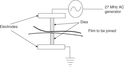
Dipole dielectric heating is accomplished by applying a high-frequency alternating electric field to a lossy dielectric polymer. The electric field is created between two electrodes with dies connected to them (Fig. 12.1). Polar polymers have polar molecular structure such that when the molecules are exposed to the alternating electric field, they tend to align in the field direction so that the positive end of the dipole will align with the negative charges according to the electric field (see Fig. 12.2). However, because of the unique high lossy dielectric properties in some polymers, when the dipoles reorient according to the high-frequency alternating electric field, their orientation becomes out-of-phase (or phase shift, movement of the molecules lagging alternating electric field) where the misalignment between the dipoles happens and as a result creates internal molecular frictional heating.

The power dissipated during dielectric or RF heating is governed by the following formula:
or
or
where
ε0 = permittivity of vacuum (8.84 * 10−12 F/m)
Erms = electric field strength (V/m)
ω = 2πf = angular frequency (f in Hz)
![]() = effective dielectric loss factor of the polymer
= effective dielectric loss factor of the polymer
ε″ = ε′ * tan(δ) (dielectric loss factor of the polymer) (efficiency of the electromagnetic energy conversion into heat) tan(δ) = ε″/ε′ (loss tangent or dissipation factor) (material’s capability of absorbing electromagnetic energy)
δ = the loss angle or the phase shift between the electric field and the molecules orientation
where ε′ = dielectric constant (or relative permittivity of the polymer – ratio of the permittivity of the polymer ε to the permittivity of vacuum, all ε′ values of polymers are >1). This value directly reflect the extent to which the polymer can be polarized.
The amount of the electromagnetic energy that will convert into heat is dependent on the atomic and molecular structure of the polymer, the frequency of the electric field and the field strength. In an electric term, we refer it to dielectric loss factor. The dielectric constant is a material property. It determines the extent of dipole polarization. The dielectric loss factor is the one that determines the conversion of electric energy into heat. This also explains why dielectric heating only works on dipolar polymers with high dielectric loss, such as PVC.
Effects of frequency and temperature
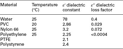
Two key material related factors that could determine the heat generation are the dielectric constant and the dielectric loss factor (or loss tangent, loss factor is defined by the product of loss tangent and dielectric constant). Table 12.1 shows the values of the dielectric constant and dielectric loss factor of some material at room temperature under 30 MHz frequency.1 One critical aspect of the dielectric constant is that both the dielectric constant and the loss factor increase when temperature increases. For dipole polarization, there is a relaxation time t defined as the time required for preferentially oriented molecules to relax back to 36.8% of the original condition upon sudden removal of the exposure from the electric field. For a given material there is a maximum value for the dielectric loss factor at a specific relaxation frequency (f = 1/2πt). In an ideal case, you want to operate the heating in a frequency range where the dielectric loss factor is at its maximum value. The other critical factor is the temperature change (increase) during the dielectric heating. When a polymer’s dielectric loss factor increases significantly with temperature during dielectric heating, a thermal runaway condition could occur and lead to thermal degradation (hot spot) of the polymer (i.e., the high temperature causes the dielectric loss to rise which causes internal heating in the polymer, leading to higher temperature and further increase in loss).
12.3 Dielectric welding/sealing process description and process parameters
Similar to other welding process, four fundamental steps of welding also apply to dielectric welding (see Chapter 10 overview of the welding of medical plastics).
Dielectric sealing is achieved by sending a high-frequency electric-field current through two or more thin layers of thermoplastic material placed between two electrodes through specific dies. The two matching dies are shaped in the image of the required seal. The dies are usually mounted on two platens that are attached to a pneumatic or hydraulic press to provide pressure during the sealing process. The high-frequency energy produces localized heating through the heating mechanism described in the previous section. Once the joint interface melts and allows their molecules to intermingle, fusion bonding between two sheets is created. The power input is then turned off, and the molten polymer is allowed to solidify during a holding period. The resulting seal strength can be comparable to the original sheeting materials.
A typical dielectric welding/sealing machine consists of these basic elements:
1. High-voltage power generator with frequency of 27.12 MHz where the system can be tuned and the total power output controlled through the electrodes and dies.
2. A pneumatic or hydraulic press where two electrodes are attached to two aluminum platens so that their movement (distance) and pressure can be controlled precisely.
3. A pair of dies made from brass are attached to the electrodes (aluminum platens) to serve as the heating elements where the final shape of the seal can be formed. The movement and pressure of the dies are controlled by the press.
4. A nest or fixture that can hold and provide support for the sheets other than the seal area during sealing process.
12.3.1 Key process requirements and parameters
Power requirement
In order to identify the right machine to use, a user must figure out the power necessary to perform a successful seal. This is mainly dependent on the total seal area for each sealing cycle. A tear seal only counts a fraction of a flat seal area. A larger area requires higher power. As a rule of thumb, 1 kW per 1000–2000 mm2 can be used to estimate the power requirement. Please consult with the sealing machine manufacturer for a recommendation. Sheet-material thickness can complicate the power requirement if it gets so thin (less than 0.01″ or 0.25 mm thick) that the dies become a dominant heat sink that prevents sufficient heating and melting of the material in between the dies. In this case, buffer material can be used as a heat insulator. The buffer material will be discussed in more detail in a later section.
Interdependency of process parameters
To some limited extent, these process parameters are interrelated. For example, higher power input can increase the heating rate of the sealing process and reduce the seal time. The pre-seal pressure can affect the seal time too because it can change the effective material thickness during sealing. Die temperature control can also impact the power input and seal time because it changes the dielectric loss and the heat loss through the dies. It is critical to identify a process window where a stable sealing process can be established with an acceptable seal quality.
Power input
Higher power input can reduce the seal time required. However, the voltage increase can lead to a more sensitive sealing process where any imperfection in alignment, material impurities, could lead to arcing and inconsistent seal quality. Most dielectric sealing machines in the market are equipped with an arc suppressor. Whenever an arc suppressor is triggered without any obvious reasons, it means the power-input level for that particular seal geometry is reaching its maximum level. To achieve a stable process is more important than to have a shorter seal time because any short circuit caused by high-power input/short seal time could damage the machine and dies where significant machine down time could incur.
Weld/seal time
The seal time is the time required for the power to stay turned on until the target (higher than melting or transition) temperature at the joint interface is reached. This is one of the key parameters to determine the amount of the melting and as a result the final seal thickness and the size of the weld beads.
Weld pressure or collapse distance
Having pressure control before and after power input is desirable. Application of pre-seal pressure is important because it will determine the effective material thickness before sealing begins. It is also beneficial to have both pressure and final collapse control, because pressure is critical to create a consistent seal and collapse control can avoid over thinning of the material at the seal interface right after melting occurs and prevent arcing.
Hold time
After the power input is turned off, the dies are held together with a preset pressure for a preset hold time. This is to make sure the molten material at the joint interface is solidified and a seal strength is established before releasing the die pressure.
Die temperature
Section 12.2.1 discussed the temperature dependence of the dielectric loss. It is desirable to control the temperature of the dies to maintain a consistent sealing process. This can be achieved by running cooling water through the metal base platens where the dies are attached to. Dies can be regarded as a heat sink during the sealing process to provide fast re-solidification of the molten layer. However, as the sealing process runs for a typical production line, thousands of seals are generated and it does not take long for the dies to become hot. If the die cooling system is not functioning properly, it is very easy for the dies to get hot. Once the dies become hot, the die heat sink effect is significantly reduced and results in higher temperature in the polymeric film which could lead to higher dielectric loss and increase in heat generation. As a result, thermal runaway could happen and lead to arcing and inconsistent seal quality. Some plastics that do not have the best dielectric properties will require pre-heating of the electrode to improve their weldability. For example, polyamide (nylon) typically requires pre-heating the electrode to about 50 °C in order to have a good seal quality.
Single-versus double-cycle process, simultaneous versus sequential
It is always desirable to complete a sealing process with one single sealing cycle. But when different seals with different power distributions are required, a single-cycle die design can be very challenging. For example, an application that requires a flat/planar seal and a circular/non-planar seal (around a rigid port) to be completed in the same sealing process can become complicated. In this case, a double-cycle sealing process can produce a much better seal quality with a simpler die design. However, it also requires a longer processing time. Different approaches on the sealing steps can also be an important factor to consider when designing the machine configuration. One good example is the sealing of medical bags where the port seals and the bag peripheral seal are needed to complete the sealing process. This can be achieved by either sealing the port seal first then the peripheral seal with sequential steps or with a double-cycle sealing process where a port seal is introduced by an additional mandrel die in between the top and bottom dies first. Then, a peripheral seal is done between the top and bottom dies with the second sealing cycle while the pressure between the top and bottom dies are maintained throughout both cycles. One main advantage of using a double-cycle sealing process over two separate sealing steps is that it is easier to maintain the seal alignment for both seals because the same fixture and sealing pressure are maintained, while the top and bottom platens are remain closed.
12.3.2 Sealing process automation
There are many different ways to automate the dielectric sealing process, depending on the throughput and how complicated the seals are. The following lists the three most common configurations are used in the industry:
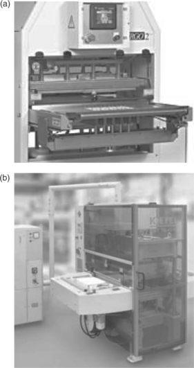
1. Semi-automatic manual loading machine: this type of machine requires the operator to manually feed the sheeting materials onto the bottom die and fixture area. The bottom platen and die can shuttle in and out horizontally and the top platen with the top die can move down vertically to match up the bottom die and generate the seal. This is the most suitable for low throughput requirements with a low capital investment (see Fig. 12.3).
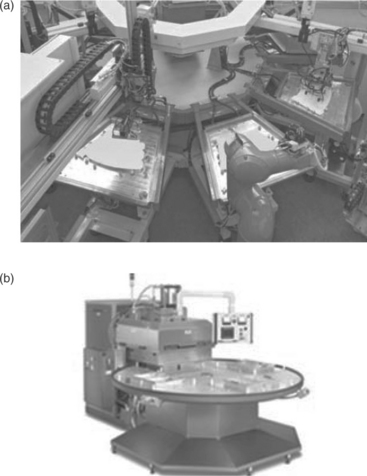
2. Turntables with indexing: this is used mainly to accommodate more complicated sealing requirements. Multiple stations are utilized to provide different sealing and other assembly processes. This can be configured with an operator feeding at different stations or an automatic feeding system at the different stations. Each station can be single- or double-cycle sealing process (see Fig. 12.4).
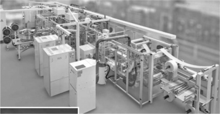
3. Linear continuous conveyer automatic machine with 2-up or more— high throughput machine: when a high throughput is needed, a much bigger machine with a linear continuous conveyer, where the film (web in roll) is fed into the machine continuously, can be used. Multiple stations can be integrated into the line where single- or double-cycle sealing process can be used for each station. Also, depending on the throughout requirement, it can be a 2-up or more for the conveyer line. Different feeding systems can be integrated into the stations depending on the part geometry and material types. As a typical high throughput medical-bag production-line machine, one can envision that two rolls of web (as top and bottom sheets) being fed into the line continuously where the web is precut and multiple stations perform the peripheral seal, tear seal, insertion of tubing as ports, and port seals, etc., depending on the applications. As a good quality-control measure, inspection and testing can be integrated into the production line at appropriate stations to ensure only a good quality product is produced. One of the key things regarding the machine configuration is the flexibility of the power-generator arrangement. This type of machine can require multiple stations with a high power requirement. Careful consideration for the extra power supply and extra space is always a good strategy. Figure 12.5 shows typical linear continuous RF welding system for blood-bag applications.
12.4 Key factors affecting the sealing process and seal quality
This section discusses key factors that could affect sealing process control and final seal quality. It provides important background information that will help engineers to understand some practical RF sealing process applications.
12.4.1 Die design
A good die design is a prerequisite for achieving a quality seal. Two key aspects determine the final shape of the seal. Firstly, if the dies are not matched perfectly, the final seal will show the mismatch and could become the weakest link of the overall seal. The other aspect is that the efficiency of the dielectric heating process is dependent on the die design.
Complex die design – non-planar and three dimensional
Traditional dielectric sealing die design is all vertical circuit flow direction from top to bottom dies. With a double-cycle sealing application, die design could become complicated because of the potential multiple circuit flow directions. This brings an additional degree of freedom to the die design where heating patterns could be more complicated and three dimensional rather than just in vertical direction.
In some complicated applications, heating has to happen on a non-planar (non-linear) surface where the dies has to be designed to follow the contour but at the same time ensuring the whole electrical system is tunable and generating a uniform electric field (heating) during the sealing process. Non-planar die design can be very tricky and any misstep may lead to non-uniform heating and result in bad-quality seal or unstable sealing process where arcing could happen. A double-cycle sealing process can simplify the die design for a multiple seals application where both a planar and a non-planar seals are required. A die design for double-cycle application usually involves multiple dies (more than two sets of die) and switching circuits during different cycles. Plate VI (see Plate VI between pages 300 and 301) shows one die set design with two potential switching circuits. Panel (a) in Plate VI shows a single-cycle welding process with a combined electrodes configuration where the electric field flows vertically. Panel (b) shows a double-cycle welding process where the electric field flows vertically for a flat seal in the first welding cycle and then flows horizontally in the ring seal in the second welding cycle. Figure 12.6 shows a seal sample that is sealed from sheet material onto a rigid port through a flat/ring seal die design using a RF sealing process.

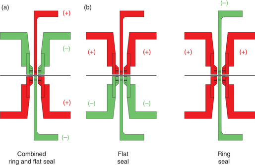
Plate VI (Chapter 12) (a) Polarity of the dies during fl at seal and ring seal – single-cycle welding process (red, positive electrode (+); green, negative electrode (–)). (b) Polarity of the dies during fl at seal and ring seal – two-cycle welding process (red, positive electrode (+); green, negative electrode (–)).
When multiple dies are in close proximity, the maintenance of the precise gaps between dies and insulation between dies are critical to the consistency of the sealing process and the quality of the seal. One way to achieve this is to incorporate insulate material such as UHMWPE with matching geometry in between the dies. Also for double-cycle die design, one must consider the distribution of the overall capacitance of the circuit due to the three-dimensional die design. One rule of thumb for this is to avoid too much overlapping areas when two active dies are in close proximity.
Tear seal die design
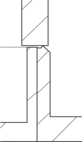
Tear seal is utilized to cut the unwanted portion of the sheeting material after the sealing process. The die design for tear seal is different than a typical seal. Figure 12.7 shows a typical tear seal die design where a regular flat seal is right next to it. These dies are actually on the bottom side. The matching top dies are just flat dies (see Fig. 12.8 for cross-section view). The tear seal is always located on the outside edge right next to a regular seal.

12.7 Bottom flat seal and tear seal (outside edge) die design; die is attached to an aluminum base plate.
Also die design should be an iterative process. For each iteration, you evaluate the seal and modify the dies accordingly as necessary. For any complicated die design, one must consider the structure integrity of the dies design because the dies have to go through hundred of thousands of cycles under pressure. Brass is a good candidate for the die material because it has electrical and material properties. One thing to keep in mind is that all die design must avoid sharp edges.
12.4.2 Uniformity is key
Uniformity plays a key role in the dielectric sealing process. Good die design is essential to ensure that the electric field created between the dies is uniform. A good dielectric sealing machine must provide precise uniform pressure application and movement control. Uniform dielectric heating is key to uniform seal quality and it depends on the uniform distance between the dies where the electric field is created. To insure a stable sealing process and consistent seal quality, dies, press platens and nest/fixture for the sheet material must provide uniform pressure (maintaining parallel) and precise movement during the sealing process.
12.4.3 Arcing
Arcing could happen when unexpected thinning of the sheet material during the sealing process. When the power input/seal time is excessive, coupled with high seal pressure, too much material squeeze-out (large weld bead) could happen and lead to thinning of the material in between the dies. When it is thin enough to reducing the material’s ability to electrically insulate the upper and lower dies, current flow between the dies and as a result arcing happens. An uncontrolled arc can damage (burn) the sheet material, the die, and even the circuit of the machine. More importantly the significant down time will incur where repair can be performed.
Arcing could also happen with inappropriate die design where the thickness of the seal or the electric-field distribution is not uniform. Sharp corners and edges on dies may also cause arcing. The die edges should always be rounded and smooth. Arcing may also occur because of dirt or foreign matter on the material or dies. To avoid this, care must be taken to keep the material and the machine clean. When arcing occurs, the dies must be re-evaluated to understand the root cause of the arcing. Modification of the dies might be necessary. Also dies must be smoothed out and cleaned thoroughly.
Arc suppression
Most sealing machine is supplied with arc-suppression devices. It enables the machine to sense the possibility of an arc and turn off the power before an arc can occur. A sensing control which can be set by the machine on different sealing areas to prevent arcing during production runs.
12.4.4 Buffers
A thin layer of polymer (or laminate) materials with high dielectric properties and (insulator/barrier material), such as Teflon, Phenolic, and Mylar, can be used for some specific dielectric sealing applications to get better process stability and consistent seal quality.
The buffers are usually placed in between the sheet material and the dies. They do not increase the heating efficiency of the sealing process. However, they can add benefits in the following ways:
1. add an extra insulating layer to provide more stable dielectric heating (prevent arcing) especially when the sheeting material is thinner than 0.01 inch;
2. serve as a thermal insulator between the sheet material and dies;
3. provide extra cushion for non-uniformity of the electric field or pressure;
4. some buffers can reduce adhesion of the seal to the dies.
But one thing to keep in mind is that when dealing with a complicated, double-cycle and continuous sealing process, it is difficult to incorporate any buffers in the sealing process.
12.5 Weldability
Like other welding process, weldability of the plastics for dielectric sealing process is a dominant factor during the initial welding-process selection. Two main material/electrical properties discussed earlier in the heating-mechanism section are the dominant factors for weldability:
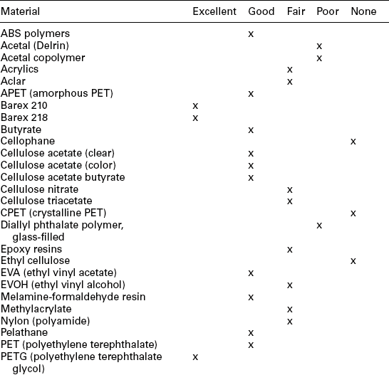
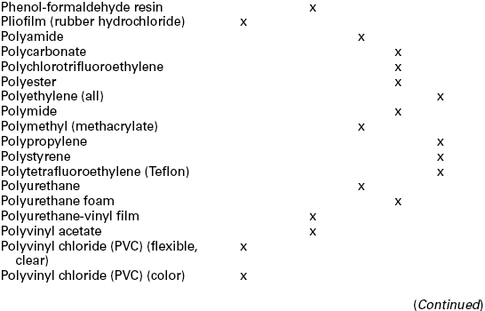
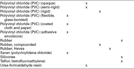
Typical materials suitable for dielectric sealing applications are polar thermoplastic polymers such as PVC (vinyl), nylons, PET, EVA, PVDC, ABS, and urethanec. Table 12.2 shows the weldability of all thermoplastic polymers. PVC has been used in the medical bags/pouches application for decades mainly because of the excellent dielectric sealing properties. Because of the environmental concerns, non-PVC materials have been under development to replace the existing PVC bags/pouches and tubing.
12.6 Testing approaches for seals and the dielectric sealing process
Testing can have different objectives during different stages of medical-device product commercialization. During the sealing-process development phase, testing is conducted to understand the process parameters and eventually optimize the sealing process. This can be done through a design of experiment process with testing of seal strength or other quality characteristics/attributes as criteria for evaluation. Two measureable test results listed below are good ways to evaluate the quality of a seal:
1. weld bead size (final thickness) and symmetry (see Fig. 12.9);

During the production process, testing is carried out to make sure that the products produced are within the specifications with the specified confidence level before releasing to end user. For a typical dielectric sealing process, there are some key characteristics that we should either monitor or test to make sure the seal quality is meeting our expectation. Some of the tests are destructive tests which have to be conducted after the product is produced. Some non-destructive tests can be done at different stages before or during the production process to reduce the rejection rate. For example:
12.7 RF welding process advantages, limitations and future trends
12.7.1 RF welding process advantages and limitations
Compared to other sealing processes, RF sealing provides some unique advantages that other welding processes can not offer:
1. Precise, efficient, and localized heating occurs from the joint interface. Figure 12.10 shows a temperature profile comparison for traditional heat sealing and RF sealing. The die temperature can be controlled to compensate for the thickness of the sheet material. Also, sticking to the die/tool is not an issue for RF sealing.

2. Some unique and complicated RF seals can be created for tubing and bag applications. Tear seals and regular seals can be integrated into the overall sealing process to streamline the process.
3. Hermetic seals can be achieved.
12.7.2 Future trends in RF welding
One of the major R&D areas in RF welding that medical-device companies are working on is the RF welding/sealing of medical pouch/bag system (with ports) using non-PVC and/or non-DEHP PVC materials. PVC material has been known for containing harmful components such as vinyl chloride monomer (VCM) and ethylene dichloride (EDC) which can release dioxin when incinerated. Also, a plasticizer DEHP (bis(2-ethylhexyl) phthalate) that has been commonly used to soften the rigid PVC for use in medical-device applications has many potential health concerns when used improperly. Many efforts from the medical-device industry are focused on identifying materials to replace PVC and yet being able to continue utilizing the similar RF welding processes. Proprietary material (including multi-layer material structures) development for bags, pouches, and ports for medical applications for RF welding is still a very active research and development area as many medical-device companies are trying to provide non-PVC and non-DEHP PVC disposable sets for applications in IV, dialysis, blood transfusion areas.
Another area of research efforts is the continuing improvement of the current RF sealing system, in particular how to simplify the integration of peripheral sealing (such as port sealing) into the main sheeting-material sealing by a combination of new die designs and new material/component configurations.