
Overview of welding methods for medical plastics
Abstract:
This chapter presents a technical review of the welding technologies for medical plastics. It covers both the fundamentals of the plastic-welding process and an overview of the major welding technologies used in medical plastics. Plastic-welding processes can be divided into three different groups based on the mechanism of heat generation: external heating methods, where the thermal energy is applied externally onto the surface of the part such as hot plate, extrusion, hot gas, laser, and infrared (IR) welding; internal heating methods, where the heating is generated mechanically, electrically, or electromagnetically by internal molecular vibration or friction at the joint interface such as ultrasonic, vibration, spin, dielectric, and microwave welding; and implant heating methods, where heating is initially produced in a susceptor placed at the joint interface and then conducted to the parent material such as resistive implant, induction implant, microwave implant, and IR/laser implant welding.
10.1 Introduction
With advances in raw polymer materials and their manufacturing processes, many plastics are able to offer flexibility, consistency and cost effectiveness in design and manufacturing processes while at the same time meeting the stringent requirements of the well-regulated medical-device industry. As a result, the usage of plastics in the medical-device industry has been increasing steadily since the discovery of synthetic polymers. More and more, plastic devices are being developed and commercialized to replace existing metal devices. Medical plastics have been used in different applications in the FDA’s device classifications (Class I, II, III), ranging from a simple tool such as a tongue depressor, to a complex balloon/stent catheter system that goes inside a human body during surgery with the stent being implanted inside a patient’s artery.
Joining plastic components becomes necessary when molding complex products (or other primary processes) is difficult and/or cost prohibitive. In other applications, joining is also needed between parts that come from different primary processes, such as between extruded sheet/tubing and molded parts. Unlike metal welding, the joining/welding of plastics has frequently been overlooked by the mainstream plastic industry. It has been regarded as a secondary operation in the plastic manufacturing processes. In many real-world examples that I have dealt with during my consulting career, welding consideration is frequently treated as an ‘afterthought’ in a typical plastic-product development cycle. In reality, however, the performance of the final product depends equally on both primary and secondary operations. Any component can be molded precisely but if assembled/welded improperly, it is still considered a reject.
Typical joining methods for plastics include adhesive bonding, mechanical fastening, and welding.
10.1.1 Adhesive bonding
Different adhesives with specific bonding processes (such as dispensing and curing) can be used to bond dissimilar plastics and thermoset plastics, as well as different types of materials such as metals and plastics.
10.1.2 Mechanical fastening
Mechanical fastening does not provide bonding between the two surfaces of the parts to be joined. The joint strength is provided by mechanically joining two parts together through pre-designed fitting (such as snap fit or press fit) or by the addition parts such as a bolt or rivet.
10.1.3 Welding
As its title implies, this chapter will focus on the welding of medical plastics and provide an overview of the main welding processes used in the medical-device industry. As the awareness of recycling and other environmental issues increase, welding is becoming a natural choice with regards to the joining of thermoplastics. The welding process itself has some attractive features:
• strong joint (comparable to parent material);
• short process time (for most medical-device applications);
• no new material (such as adhesives) is required except the implant welding processes;
• it can be automated and integrated into manufacturing processes.
An array of welding techniques is available for different applications. Choosing an appropriate welding method can directly affect the product integrity and the manufacturing cost. Many criteria can be used to select an appropriate joining method but the decision is usually based on the following variables: application of the joint, cost, process time, reliability of the joint, material issues, additional manufacturing processes required, operating conditions, loading, geometry, weight, and size. This chapter is intended to provide a brief overview of different welding techniques for medical plastics. It will also compare the benefits and limitations of the welding techniques in relation to other medical-device manufacturing processes.
10.2 Fundamental processes of plastics welding
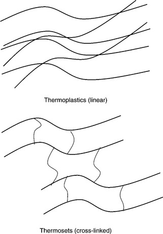
Plastics can be categorized into thermoplastics and thermosets. Thermoplastics can be softened and melted upon heating. Thermosets, on the other hand, cannot be softened or melted once they are made due to their cross-linked structure (see Fig. 10.1). Because fusion is required for the welding process, only thermoplastics can utilize welding as a joining process.
There are four fundamental steps in a welding process – heating the joint surface, application of pressure, intermolecular diffusion and cooling.1
Heating of the joint surface is the most important step. Different welding methods differ in the heating method that is used. The heating can be divided into three types (see Fig. 10.2):
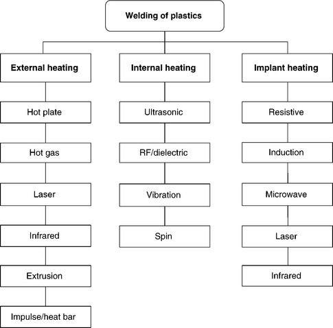
1. External heating: heat is externally applied onto the surface of the part. Typical processes are:
2. Internal heating: heat is generated by internal molecular vibration or friction at the joint interface. The energy sources can be mechanical or electric/electromagnetic. Typical processes include ultrasonic, vibration, spin, and RF/dielectric.
3. Implant heating: thermal energy is produced by heating a susceptor (energy absorber) at the joint interface where the energy sources can be converted from different types of energy such as electrical or electromagnetic energy. Typical processes are induction implant, resistive implant, microwave implant, and infrared/laser implant. Two key characteristics of the susceptors are the ability to absorb the energy from the particular energy source and the ability to provide compatibility (weld-ability) between the two pieces of the parts to be joined.
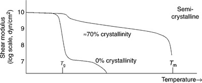
Different materials require different levels of heating. As a rule of thumb, semicrystalline thermoplastics require a heating temperature higher than the melting temperature. And amorphous thermoplastics require heating temperatures higher than glass transition temperature (see Fig. 10.3). The corresponding process parameters for the heating process are heating time and temperature. Controlling heating time as a process parameter ensure that a sufficient molten layer is created during the heating process such that the uniform diffusion process at the joint interface can occur under the preset pressure, ensuring that a strong joint strength can be achieved.
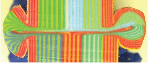
Application of pressure presses two melted parts together to have an intimate contact at the joint interface. Some heating (welding) methods require higher pressure because the heating is generated by relative mechanical motion between two parts such as ultrasonic, vibration, and spin-welding processes. The corresponding process parameters for this particular process are weld force/pressure and hold time. An analytical force/pressure application process can be described as a squeeze-flow process that is commonly observed in polymer processing. Plate II (see Plate II in color section between pages 300 and 301) shows a flow pattern of the joint interface of a hot-plate welded-plastic sample. It is important to note that the final material left in the joint interface is the material that comes from the central portion of the molten layer. The original top surface of the molten layer is squeezed out and forms weld beads at the side.
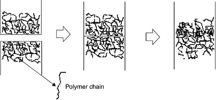
Intermolecular diffusion is similar to the healing of the polymer–polymer interface. The main purpose is to let the chain molecules move across the interface to create chain entanglement (see Fig. 10.4). The important aspect of this is the time required for the complete healing. Many studies have shown that the time required for healing is much less than the time required for flow and wetting.
Cooling is the process when the melted polymer is resolidified to provide structural strength. The cooling rate may have some effect on the microstructure of the semicrystalline thermoplastics. This becomes more pronounced when a large molten layer is created in a welding process such as hot-plate welding. But in many cases, short cooling times are more desirable for cost reductions.
10.2.1 Key welding process parameters
Based on these welding steps, there are some common process parameters:
(a) temperature of the heating element;
(c) power/energy related terms (current level, watts, etc.).
(a) Depending on the welding processes, a preset pressure is applied during or after the heating/welding process.
(a) A specific collapse or travel distance during welding could be used to control the completion of the welding process.
(a) Cooling time is part of the cycle time required for the welding process. Welding process with a larger heat-affected zone will require more cooling time and results in a longer process/cycle time.
6. Good fixturing to ensure a uniform energy and pressure is applied over the joint interface.
10.3 Medical plastics and weldability
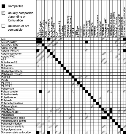
Depending on the application there are different requirements for medical-device development. Typical key requirements in the medical-device development are biocompatibility, plastic material performance, and manufacturing processability. If welding is one of the manufacturing processes required, the weldability must be considered in addition to other requirements when choosing the plastic materials. Ideally, one should always try to use the same or similar plastic for the two parts to be welded if possible. However, in the real world there are limitations on material selection depending on the applications and designs. Figure 10.5 shows a weldability table that lists the compatibility of different polymers that can be used as a reference to aid selection of appropriate plastics for general welding considerations. This table should be used as a starting point just for compatibility considerations. There are other welding-related factors affecting the selection of the plastic materials for medical devices, which will be discussed when different welding processes are covered in later sections of this chapter.
10.3.1 Alloys and copolymers
Two key subsets of polymer materials are alloys and copolymers. They offer unique properties for specific applications. Their weldability is more difficult to estimate but as a rule of thumb welding between similar materials should produce acceptable weld strength for specific applications. Based on the alloy combination, one can also expect that welding strength between two plastics that could form an alloy is generally acceptable. For example, welding between these plastics might be able to produce weld strength well above the particular application that you are looking for:
10.3.2 Plastic with fillers or regrind
In general any increase of fillers or regrind in the plastics means less virgin polymer available for welding purpose. The weld strength will be reduced as the content of filler or regrind increases.
10.3.3 Moisture
Some polymers are hygroscopic, such as polycarbonate, nylon, polysulfone, and PET; if the materials are not dried or exposed in a high-humidity environment before welding takes place, foamy structure (air bubbles) could occur at the joint area. Larger heating area will make the condition worse. As a result, joint quality will suffer. In general, it is desirable to do welding right after the molding process with minimal exposure to the high-humidity condition. If this is not possible, an additional drying process will be necessary before the welding process takes place.
10.3.4 Special additives and colorants
Additives are considers as impurity or foreign material to the base polymer. These usually reduce the weldability. Colorants do not usually interfere with welding, but titanium dioxide used as a white pigment has some noticeable impact on the weldability.
10.3.5 Testing of weldability
There is an easy and straight forward way of manually testing the weldability between two unknown plastics:
1. Prepare a hot metal plate that is capable of producing a temperature for up to 400 °F. Use a sheet of fiber-reinforced Teflon cloth as a non-stick coating by clipping it on the metal plate surface.
2. Prepare two test bars (similar to a regular tensile test specimen) out of the plastic on which you want to do the weldability test.
3. Hold the test bars against the hot plate (the temperature should be higher than Tg or Tm of the plastic) with a small pressure until a small molten layer form on each bar (usually takes around 5 s).
4. Quickly remove the bars from the plate and carefully align and push the two molten layers against each other and maintain the pressure for another 10 s to let it solidify and cool down.
5. If these two plastics are compatible/weldable, the joint should be able to hold up when you try to pull them apart.
10.4 Part and Joint Design
Joint-design considerations for welding processes should be treated as part of DFM/DFA (design for manufacturing and assembly) process. In my past experience as a consultant, joint design for welding processes is frequently treated as an afterthought. Many parts are designed and prototyped without having an appropriate joint design based on an appropriate joining/welding process. As a result they fail to meet the final functional requirements and are forced to be modified in the last-minute scrambling.
A good joint design is a critical step in achieving final joint results. Depending on the welding processes selected, there are different joint designs available. As a rule of thumb, welding processes that use mechanical movement/vibration (such as ultrasonic, vibration, spin-welding processes) as a heating mechanism have a critical and sensitive joint design to the final joint strength because the efficiency of the heat generation is dependent on the design.
One key concept about the joint design is to integrate it into the overall part design. Here are some factors that need to be considered during the joint- and part-design stage:
1. To simplify difficult molding or manufacturing processes: When a complicated part geometry prevents a molding tool design or a molding process from producing the whole part, it can be molded into two or multiple parts and then joined together by a welding process. In this case, how and where to separate the complex part into two or more parts could be limited by the molding process, additional manufacturing process required, or the available welding process to join the parts together and provide sufficient joint strength. For example, some of the smaller medical-use filters are put together by welding two top and bottom molded halves with a membrane in between.
2. Functional or strength requirement for the joint (geometry of the joint): Is there a specific functional or strength requirement for the joint? In some cases, a hermetic seal is required to create an enclosure when joining two halves together. In other cases, depending on the joint-strength requirement, joint design could be all around the joint interface or it could be just at some intermittent spots (designed to be breakable or detachable).
3. What welding process can be used? Different plastic materials and welding processes usually require different joint designs. Even with the same welding process, depending on the functional requirements, the joint design could be different too. Welding-related aspects of the joint design will be discussed separately in the later sections of the welding processes.
The typical joint designs are described below (see also Fig. 10.6):

(a) Butt joint: this is the most straightforward joint design for welding process. The joint interface is perpendicular to the direction of the force application.
(b) Lap joint: two joining surfaces are joined by overlapping onto each other.
(c) Tongue and groove joint: joint interface is a matching male (T shape) to female (U shape) joint design. This joint design provides self-aligning and is more suitable for hermetic-seal applications. However, there is a requirement on the minimal wall thickness especially for the ultrasonic welding process.
(d) Shear joint: this is a special joint design for ultrasonic welding where an interference between two matching parts is required. This is also a good joint design for hermetic-seal applications.
(e) Step joint: this joint design has a step where it provides more joint area and a mean of alignment.
10.5 Processes with external heating
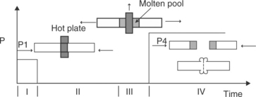
This is when heat is applied externally onto the part surfaces to be joined. The heat source can be a hot plate, hot gas, or infrared heater. After the surfaces are melted, the heat source is removed and the two melted interfaces are pressed together. Unless the parts to be welded have thin enough material that heat can be transferred from the heating surface (such as thin film) to the joint interface quickly, these two parts have to be heated separately and then brought together under a preset pressure – that is, a change-over time will need to be included in the overall process cycle time.
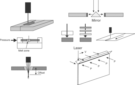
10.5.1 Hot-plate welding
Hot-plate welding uses a contact-type heating process (see Fig. 10.7). Heat is carried out by thermal conduction from the hot plate to the parts. Hot-plate welding is not a popular welding method used in medical-device industry because it is more suitable for large parts and requires a longer process time. However, it offers simple process control and very consistent results. The size of the part can be as big as the hot platen. It can be an irregular shape as long as the temperature on the platen is uniform. Good control of the heating temperature and heating time is required to ensure uniform melting at the joint interface. It is possible to weld dissimilar but compatible thermoplastics using the hot-plate process. Two hot platens with different temperature setting are required to compensate for different melting temperatures of the compatible plastics. Butt joint is the most common joint design used for hot-plate welding. Also, the hot-plate-welding process will create a weld bead where the molten material is squeezed out during the welding process.
10.5.2 Heat sealing/welding (impulse sealer)
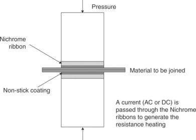
The heated bar or impulse heat sealer is commonly used to seal thermoplastic thin films and laminates. The process is very similar to hot-plate welding process. The heating energy is provided by a two heated bars (maintained at the heating temperature) or two resistive thin metal stripes (heat generated only when the current passing through the stripes is turned on). PTFE or Kapton film is usually used in between the heating element and the films to be welded as a non-stick layer. During the welding process, pressure is applied onto the films in between the heating elements. In some cases, if the film is thin enough for heat to be conducted through the film quickly, one-sided heating element can be sufficient. For the heated-bar sealing process, sometimes a cooling tool with a shape similar to the heated bar can be used to cool down the joint interface right after the heating process to help re-solidify the joint area and prevent the reopening of the joint. The key welding parameters are bar temperature, welding time, and weld pressure. The main application for this welding technique is to seal of packaging materials such as blister pack and tray. The heated-bar sealing process can also be used to seal a small membrane onto a plastic substrate.
Impulse welding is the process by which electricity is used to create heat through a high-resistance wire (see Fig. 10.8). The wire is typically nickel– chromium encapsulated in a non-stick coating. A current will cause the wire to heat rapidly then transfer to the materials. Traditional impulse welding processes have limited controls over the heating and cooling cycles. This results in a continuous heat build-up in the machine cycles, negatively affecting the repeatability of subsequent welds.
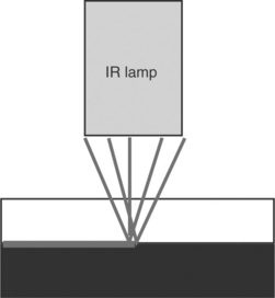
10.5.3 Infrared welding
Infrared welding uses a non-contact type heating process (see Fig. 10.9). Heating is carried out by thermal radiation from the infrared lamp. The radiation wavelength is dependent on the temperature of the heating element following Wien’s law (see equation below). Figure 10.10 shows the wavelength distribution of a typical quartz halogen IR lamp at different temperatures. At the peak temperature, the corresponding wavelength is around 0.9 μm. Figure 10.11 shows a relatively low absorption of a typical natural-color plastic material around the near IR wavelength. This wavelength range is suitable for through-transmission welding applications.

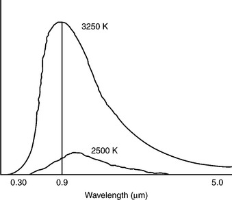
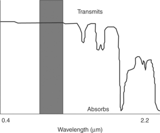
Figure 10.11 IR lamp near infrared wavelength transmission for most of the transparent (or natural-color) polymers.
Different thermoplastics and thermoplastics with different pigmentation absorb infrared energy differently. Black thermoplastics absorb more infrared energy than other color materials. Natural and transparent thermoplastics usually have the least absorption. Studies have been done in this area on characterization of IR heating absorption.2 Figure 10.12 shows how the carbon black content in polyethylene could impact the heat absorption efficiency for IR welding. For a typical quartz halogen IR lamp, you begin to see the impact of the heat absorption when the carbon black content level in a polyethylene thin sheet is greater than 0.06%. Therefore, selective heating (through transmission) is possible for infrared welding (lap joint with transparent layer on top or an absorbing layer between two transparent parts to be joined, see Fig. 10.13). Through-transmission, welding can be operated in step-wise or continuous mode where either the heat source or the work piece can move or rotate at a constant speed.

Figure 10.12 IR heating absorption efficiency (measured by temperature) of polyethylene with different carbon black levels.
For direct-heating butt-joint operation (non-contact, external heating), the infrared process is very similar to hot-plate welding. Heating time and heating distance are the variables that control the amount of heat input. One key advantage of the direct IR over hot-plate welding is that the heat source only needs to be turned on during the heating cycle. No preheating is required as in the hot-plate welding process. However, this type of operation works better with darker-color plastic parts because transparent or light-color parts will have much less energy absorption with a high-intensity quartz halogen IR lamp, and, as a result, very inefficient heating. Some other lower-intensity radiant heaters with lower peak temperatures than the quartz halogen lamp can actually have higher heating efficiency even with natural-color plastic parts because of their longer wavelengths and higher energy absorption.
Limitations of infrared welding include a shorter lamp life and the availability of different size/shape of the lamps. Currently, only line and spot heating elements are available for high-intensity lamps, but some heating patterns can be achieved by combining spot heaters together. Furthermore some translucent parts could actually absorb IR radiation energy (melting at the top surface) during through-transmission welding. However, studies have shown that as long as appropriate filters are applied, a good-quality weld can be obtained.
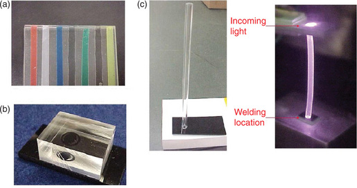
Due to the limitations and suitability for specific applications, infrared welding has not been used widely. However, it has great potential because of its unique characteristics of radiant heating. Many research studies have been conducted on how to combine, enhance, and transport the IR energy to the joint area efficiently. Different approaches have been evaluated in utilizing light pipes (quartz rods), fiber-optic bundles based on single and modified multiple focusable IR spot lamps. Plate III (see Plate III in color section between pages 300 and 301) shows some examples of the welded parts using these techniques. In my opinion, through-transmission IR welding is underutilized because it is not readily available commercially. Most of the commercial IR welding machines are targeted to replace traditional hot-plate welding machines. More development work is needed to further advance the through-transmission IR welding for specific commercial applications.
10.5.4 Laser welding
Laser welding has a much greater heat density than infrared welding. Unlike infrared, laser has a single-wavelength radiation. Nd-YAG, CO2 and diode lasers are the most frequently used lasers for joining thermoplastics. One unique characteristic of laser is the high-energy concentration and the precision of the heating area. The wavelength of a laser determines the material interaction between the laser and the plastic materials. Most thermoplastics are considered opaque with the wavelength of CO2 laser. On the other hand, YAG and diode lasers have much shorter wavelengths and can penetrate through some transparent and natural-color plastics with minimal absorption. Similar to the infrared processes, different materials and pigmentation may affect the absorption efficiency of the laser radiation. These effects can be suitable for selective heating (through-transmission welding or implant-laser welding) for YAG and diode lasers. For example, if you have an application where you need to melt the transparent tubing from external surface, the CO2 laser will be a better choice than the YAG or diode lasers. However, if you have an application where a transparent tubing overlaps a dark tubing inside, then YAG and diode lasers can be used to create bonding at the interface of these two tubings. YAG and diode lasers are also suitable for fiber-transmission beam delivery, which makes the laser-welding process much simpler and more flexible. Figure 10.14 shows different laser-welding-process configurations. Laser welding is not the most commonly used welding process because of its high-capital and maintenance costs. However, with the unique heating characteristics and price reduction of the laser systems as laser technology advances more and more applications of laser welding are expected in the future.
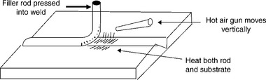
10.5.5 Hot-gas welding
Hot-gas welding is not a common welding technique used in the medical-device industry. In traditional hot-gas welding, heating is done by directing hot gas or air at the joint area to melt the surfaces (see Fig. 10.15). A filler rod is used for some joint designs. It usually has the same composition as the substrate. Both the filler rod and substrate surfaces are melted and then welded. In most of the cases, compressed air is a popular choice. In some cases, non-oxidizing gases such as nitrogen are used for oxidation-sensitive materials. Unlike the traditional hot-gas welding process, for medical-device applications hot gas can be used as a non-contact heating source for preheating, fusion, and welding applications. In the welding case, no additional filler rod is used. One thing to keep in mind is that hot-gas heating is not very uniform or precise. If non-contact hearing is required, I would suggest looking into IR heating rather than hot-gas heating.
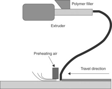
10.5.6 Extrusion welding
Extrusion welding is similar to a combination of hot-melt adhesive and hot-plate or hot-gas welding (see Fig. 10.16). It is not commonly used in the medical-device industry. The melted polymer is injected into the weld zone with the hot gas or a heated shoe preheating the substrates to be joined. The injected polymer should be the same material as the substrate. The heated shoe is usually coated with PTFE and can come in different shapes to suit different part geometries. The application of extrusion welding is similar to that of hot-gas welding. A skilled operator is needed when manual welding is used.
10.6 Processes with internal heating
One unique aspect of this internal-heating welding process is that the heating and application of the pressure occurs at the same time throughout the welding process. This eliminates the change-over time and offers faster overall process time.
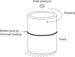
10.6.1 Spin welding
Frictional heating is generated by rotating one part against another under pressure (see Fig. 10.17). One part is fixed while the other is rotated with a controlled angular velocity. Spin-welding machines are equipped with either a flywheel which allows presetting of the energy level, or a servo motor which can control the speed and orientation precisely. Spin welding can produce high-quality welds with a short process time and good reproducibility, but it is only suitable for circular parts (or parts with circular bondlines). It can produce good strong weld but it generates weld flash during the welding process. Typical butt, shear, tongue, and groove joint designs can be used for spin welding. A joint design with a flash trap should be considered if flash generation is a concern for the product. It is possible to make welds under liquid environments but higher-energy input will be required because of the energy dissipation into the liquid.
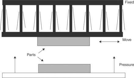
10.6.2 Vibration welding
In vibration welding, heating is generated by rubbing two bars linearly under pressure and at a preset frequency and amplitude (see Fig. 10.18). Usually the process works best when the joints are planar, but parts with angles of less than 10 ° are weldable. Short process times and narrow weld zones make the process more tolerant of moisture in the polymer. Typical joint designs are butt joint and tongue and groove with a flash trap. Typical amplitudes range from 0.5 to several millimeters and frequencies range from 100 to 500 hertz. A typical vibration-welding machine is quite big and expensive compared with other welding processes. It is more frequently used for unique applications that are challenging for other welding processes such as large-part and/or difficult to weld high-temperature semicrystalline plastics. It is commonly used in the automotive industry rather than in the medical-device industry.
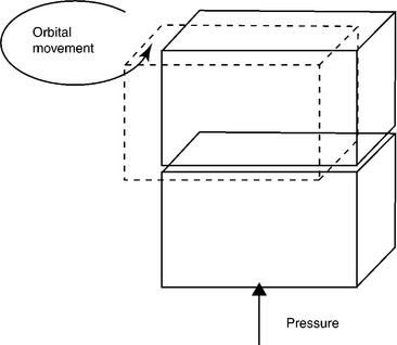
Orbital-vibration welding (see Fig. 10.19) is a newer approach. The main advantage with orbital welding is that it can be used to weld large structures with much more uniform joint strengths than the traditional linear-vibration-welding process.
10.6.3 Ultrasonic welding
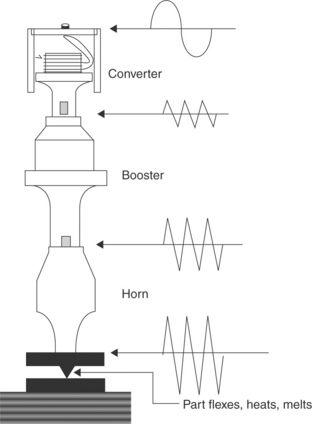
High-frequency (15–70 kHz) vibrational energy is transmitted vertically to the joint surface by a horn assembly during ultrasonic welding (see Fig. 10.20). The asperity on the joint surface dissipates into heat and leads to the melting of the joint surface. Important process parameters include the amplitude of vibration, welding time, collapse distance, welding energy, and welding pressure. The higher the operating frequency, the smaller the horn required. For a joint area smaller than the size of a dime, 40 kHz or higher is preferred. Ultrasonic welding is the best choice for amorphous thermoplastics because they are more rigid and have a more definitive transition temperature. Some semicrystalline thermoplastics can be ultrasonically welded at distances from the horn up to about 6 mm (near field welding). For far-field welding (distances longer than 6 mm), amorphous thermoplastics have a better chance of being successfully welded. Joint design is important in ultrasonic welding. Typical joint designs include the energy director and shear type. An energy director is an artificial asperity which is molded in the bondline for initial melting to occur. A shear-type joint design is like an interference between two parts. This type of joint design is more suitable for semicrystalline thermoplastics. Ultrasonic plunge (step-wise) welding is usually limited to small parts, but scan (continuous) welding (parts are moved at a constant speed) can be used for thin long parts. Ultrasonic welding is the most commonly used welding process for plastic joining and is used in all sorts of industry sectors including the medical industry. 40 kHz ultrasonic welding machines are particularly useful for many small medical components. Chapter 11 discusses ultrasonic welding in more detail.
10.6.4 Dielectric (RF) welding
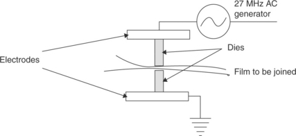
Dielectric heating operates at a high frequencies at in multiples of 13 MHz, typically at 27.12 MHz. The alternating electric field delivered by electrodes forces the dipoles in polar molecules to rotate and generate heat (see Fig. 10.21). This method is good for thin and polar materials such as PVC, polyurethanes, and polyamides. Design of dies (connected to electrodes) is important for RF welding because the final joint shape and quality depends mainly on the dies. It can be designed to have decorative edges or to precut the surplus material for manual peeling. This method is commonly used in medical/health care applications such as for bags or pouches. Chapter 12 discusses dielectric welding in more detail.
10.7 Processes with implant welding
Implant welding requires an additional susceptor (energy absorber) at the joint interface to provide the localized heating. Two key characteristics of the susceptors are the abilities to absorb the energy from the particular energy source and to provide compatibility (weldability) between the two pieces of the parts to be joined. One critical aspect of this type of welding is that the selection of the susceptor material must meet the biocompatibility requirement of the particular medical device’s intended use.
10.7.1 Induction-implant welding
When an eddy current is induced inside the conducting material such as graphite fiber, metal, carbon powders or metal foils, resistance heating occurs (see Fig. 10.22). Usually, the electrically conductive powders or fibers are mixed or braided with thermoplastic powders or fibers that are used as heating susceptors. The susceptors are implanted in the bondline and will remain in the bondline after welding. It is a non-contact heating process. The electromagnetic field is applied to the work pieces by a coil, which is connected to a power generator. Coil design and fixturing are critical to achieving efficient and uniform heating. The fixturing should be made of electrical non-conductive material that can provide pressure during the welding process to ensure intimate contact at the joint interface. An induction generator converts 60 Hz electrical power to kilohertz (kHz) or even megahertz (MHz) range high-frequency power.
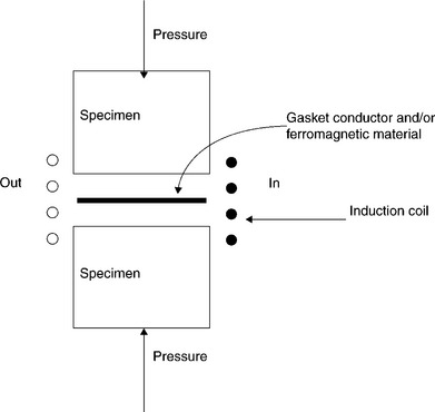
One main advantage of this method is that the joint can be three dimensional as long as the coil design can provide a uniform heating. One popular application for both medical and food packaging is the sealing of metal/foil packaging material such as foil laminate used in a pouch or bottle-cap seal.
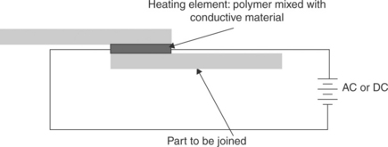
10.7.2 Resistive-implant welding
This process is similar to induction-implant welding except that the heating is generated by directly passing a current to the heating susceptors (see Fig. 10.23). A three-dimensional and large/long joint can be achieved by this method. Due to the complexity of the process and the need for an additional compatible susceptor, resistive-implant welding is only used in very unique applications.
10.7.3 Microwave-implant welding
Typical microwave welding operates at 2.45 GHz (see Fig. 10.24). Different materials can be heated by microwaves with different mechanisms. Ionic current can be generated in polymers with a high carbon black content. Dielectric losses (heating) are generated when dipoles try to reorient themselves under the field. Sensitizing materials such as carbon black or highly polar organic materials can be blended with polymers to make sensitizers heating susceptors. In microwave heating, the dimensions of most parts are smaller than, or of the same order as, the wavelength. The basic concepts of low-frequency electrical principles have to be replaced by the concept of ‘electromagnetic waves’: energy is generated with magnetrons, transmitted via wave guides, and emitted from resonating spaces or cavities.
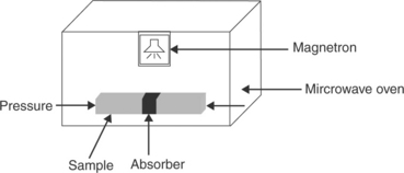
Microwave heating can be operated in either single-mode or multi-mode. For the single-mode operation, a wave guide is needed. The cavity can be tuned to have high-efficiency heating. For the multi-mode operation (domestic microwave oven), a metal fan is employed to stir the field and make it more uniform. Microwave welding is a relatively new welding process. Theoretically, it is possible to design a microwave-heating system that will generate a uniform heating for a complex joint geometry (three dimensional).
10.7.4 IR/laser-implant welding
Because the ability to absorb IR/laser radiation energy is different from different plastics and different pigmentation, it is possible to do implant welding by placing an absorbing layer, such as black polymer, in between two IR/laser transparent plastic parts to initiate the heating (see Fig. 10.25). The susceptor can be made of the same polymer as the part to be joined with the addition of carbon black pigmentation.

10.8 Potential impacts from other manufacturing processes
There are different primary manufacturing processes for medical plastics, such as molding and extrusion. These are the processes that convert the raw polymer materials to components. Welding and assembly processes are considered secondary manufacturing processes and usually take place after the primary manufacturing processes. The other important process that could happen before or after the welding process for medical devices is the sterilization process. Usually, sterilization processes have a minimal impact on the welding process. Here are some factors that should be taken into consideration in the overall manufacturing processes and weld quality control:
1. Gamma and E-beam radiation sterilization:
(a) Radiation sterilization can potentially cause cross-linking in some polymers. This could potentially reduce the weldability of the polymers.
(b) Process temperature for E-beam sterilization is much higher than gamma radiation. More stress relaxation could happen in E-beam process.
2. Steam sterilization (autoclaving): steam sterilization could potentially distort parts because of the high process temperature (120 °C heating) and exposure cycle. Typically, autoclave uses terminal sterilization where the sterilization process is done with the final product. This means that the sterilization process is done after all assembly processes are completed, including the welding process. Therefore, the weldline must withstand the sterilization thermal cycle and maintain its functional requirements, such as seal integrity.
3. Ethylene oxide (EtO) sterilization: one critical aspect for EtO sterilization is that the residual EtO should be removed completely. Therefore, one consideration is that the weld joint design should make sure that there will be no chance of EtO entrapment after a weld is made.
4. Welding of two components made from different primary processes: in a situation where welding of similar polymers takes place but one part is made from molding and the other is made from extrusion process. One needs to anticipate that plastic parts coming from the same polymer-grade raw material might behave differently during heating because different primary processes were used. For example, extrusion parts will have a highly oriented molecular structure. During welding when (heating takes place), the extruded parts could distort more than the molded parts because highly oriented residual stresses inherently exist in the extruded parts. For this type of welding application, it is desirable to select a welding process with more localized heating area.
10.9 Special applications for welding of medical plastics
In this section we extend our discussions to the welding of medical plastics for certain specific applications in the medical device industry.
10.9.1 Radiation welding of fluoropolymers
Some polymers have molecular weights that are too high for conventional processing
Teflon (PTFE) and UHMWPE are polymers that share similar characteristics. Teflon has a high melting temperature of 327 °C and when it melts it forms a gel that cracks when force is applied. However, because of its unique properties and characteristics, Teflon is widely used in medical-device applications. In a conventional process, PTFE particles are sintered into shapes or bulk forms. Welding of PTFE to PTFE directly is very difficult because of the unique characteristics of the PTFE. However, a different form of fluoro polymer, Teflon PFA, which is very similar to PTFE due to its chemical structure, can be processed conventionally. PFA is clearer than PTFE with a lower melting temperature of 310 °C. Because of the processability of the PFA, it can act as a hot-melt glue for PTFE.
Welding of Teflon can be done with traditional welding techniques using Teflon PFA as a hot-melt glue as long as the high melting temperature can be achieved. However, for a clean and good-quality weld, through-transmission radiation welding will produce the best results. The radiation energy source can be from infrared lamps or YAG or diode lasers.
In through-transmission radiation welding, radiation light passes through a transmitting PTFE polymer onto an absorbing PFA polymer that is in contact. Natural PTFE looks white but it is very transparent to both IR and lasers in 1 micron wavelength range. The key is to add pigment (such as carbon black, low percentage is fine) to the PFA to turn it into an absorbing material for IR and laser in that wavelength range. During the welding process, heat will be generated at the PFA absorbing layer and melt both PFA and PTFE to create a good joint interface. A good welding result can be obtained through good control of heating temperature of around 340 °C with a longer weld time combined with uniform pressure during welding. Plate IV (see Plate IV in the color section between pages 300 and 301) shows welded PTFE samples using the through-transmission IR principle with black PFA at the joint interface.

10.9.2 Joining of catheters using laser and infrared bonding (welding) technology
One special application in the medical device is the laser welding of the catheters. I was involved in the early development of the laser welding of catheters in the late 1990s. Since then, laser-welding applications of the catheter system have taken off. It has been used in percutaneous transluminal coronary angioplasty (PTCA) catheters where the welding of the balloon to the catheter is applied. Both butt and lap joint designs can be used to laser weld catheters in different applications. There are many custom-built laser-welding machines available for catheter applications in the medical-device industry.
There are two types of joining techniques in the assembly of plastic catheter products. The first type is adhesive bonding. The other type is welding or thermal fusion bonding. The only advantage of adhesive bonding is that it can be used for bonding thermoset plastics or bonding between two different plastics. However, because of the small dimension for the catheters, the bonding process (dispensing of adhesive, fixturing, and curing) requires very precise process control. As a result, getting a consistent joint quality could be a challenging task.
Welding, on the other hand, does not introduce additional chemicals during the process. Some type of energy source is needed for fusion bonding to occur. For the traditional catheter joining process, two types of welding techniques are used: hot air and RF welding. For both techniques, heat is applied to the surface of the tubular part and then conducted to the joint interfaces. The main challenge for the traditional welding is the efficiency and precision of the heating. Hot air is intrinsically an imprecise heating process due to the uncontrollable air flow. RF welding is actually an indirect heating process where heat is generated in a heated tool by RF energy and then conducted from the tool to the surface before finally being transferred to the joint interfaces through thermal conduction in the plastic. Because of the large heating area and poor thermal conduction, these traditional welding methods cannot control the heating at the joint interfaces precisely and consistently. Also, for balloon catheter bonding applications, it could be even more challenging due to the thin balloon wall that could be damaged easily by imprecise heating. A large heating area also means the mechanical property of the joint area of the catheter could change and compromise the functional performance of the catheter.
Unlike traditional welding methods, laser welding offers a precise and localized heating – a key advantage over traditional welding. Other than precise heating, one unique process characteristic is the ability to do either direct heating or through-transmission heating by selecting an appropriate laser to match up with the right material. These characteristics have made laser bonding very attractive to the catheter assembly process. For example, the CO2 laser has a longer wavelength of 10 600 nm, where all the plastics are opaque to the laser and will absorb the laser energy directly. On the other hand, for Diode or YAG lasers, due to their shorter wavelengths (from 800 to 1064 nm), the laser energy can pass through the natural or transparent plastics and facilitate through-transmission welding (please refer to Section 10.7.4). One of the biggest advantages for Diode and YAG lasers is that they are suitable for fiber-optic transmission which simplifies beam delivery and makes it easier for high-speed applications. However, pure through-transmission welding cannot provide a good surface heating to smooth out the transition area around the tubing edge as in with the CO2 laser. Especially for joining balloon to catheter (PTCA application), the CO2 laser can heat and melt the thin outer layer efficiently and bond the outer layer to the catheter uniformly and consistently with low energy consumption.
Another welding technology similar to laser that can be used for catheter joining is infrared (IR) welding. The typical IR lamp energy intensity is not as high as the typical laser and it cannot be focused down to as tiny a spot as in a laser. However, because it is not monochromatic like a typical laser and its wavelength is distributed around 1 μm, it can offer the benefits of both direct and through-transmission welding (combination effects of YAG/diode and CO2 lasers). Two critical areas that could help IR welding become more suitable for catheter application are an increased heating intensity with more focus area and a better control of selective (through-transmission vs direct) heating. Many studies have been done with IR welding of plastic parts in recent years, and I am confident that once more R&D effort is put into the IR welding for catheter application its great potential will be realized.
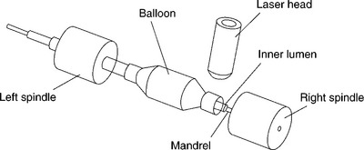
Similar to other welding processes, catheter bonding/welding requires precise process control and fixturing. Figure 10.26 shows a typical balloon and catheter laser-bonding process where a rotating mandrel and spindle welding set-up is used to maintain a uniform heating and pressure. The main focus is always on how to apply the heat and pressure uniformly during the welding process. The laser heat source can move along the spindle axis to control the bond length and multiple bonds.
Different approaches are utilized to control the application force and final shape of the joint areas of a catheter and balloon parts. Utilizing fixtures with high temperature shrink tubes (such as FEP, fluorinated ethylene propylene) or glass molds under a heat source such as a hot-air station is the traditional way to form or fusion bond catheter and balloon applications. Without doubt, laser or IR as a heat source can offer more flexibility in the fixtures and produce products of more consistent quality.
10.9.3 Solvent bonding/welding
Solvent bonding/welding is not the most environmental friendly method to join plastics but it does provide a unique and efficient joining method for some medical plastics (mainly amorphous) including PVC, ABS, PC, Acrylic, and PS. For medical-device applications, solvent bonding is widely used in bonding tubings and ports for blood or IV solution bags, mainly because of the circular joint interface with a pre-designed interference provides a perfect way to maintain an intimate contact between two parts without any additional fixturing.
The processes of solvent bonding/welding is similar to a typical welding processes (see Section 10.2) except the heating energy is replaced by the solvent and the cooling is replace by the evaporation/drying:
The key principle for solvent bonding is to use solvent to dissolve surfaces to be joined and allow movement of the polymer chains in between the joint interface. In other words, the two polymers to be joined need to be compatible to each other in order to create intermolecular chain movement across the joint interface.
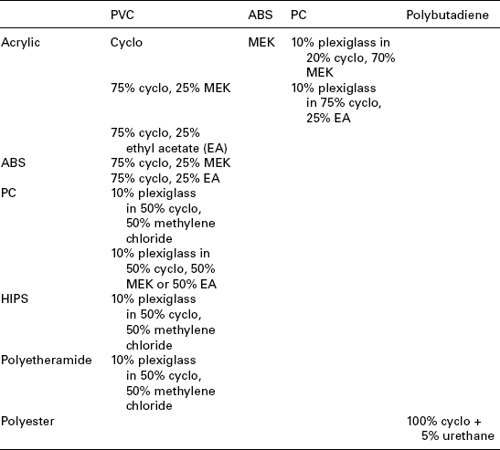
Examples of compatibility of polymers for solvent bonding:
2. Similar polymers that can form an alloy or mixture (have common solvent):
(a) bonding acrylic to ABS using MEK (methyl ethyl ketone);
(b) bonding acrylic to PVC using 75% cyclohexane and 25% MEK.
3. Different polymers that are not compatible and do not have a common solvent but have a mutually compatible polymer:
One important note to keep in mind is that many amorphous polymers that can be solvent bonded are also vulnerable to environmental stress cracking. Therefore, the selected solvent should not act as a stress crack promoter for either one of the plastic materials to be joined.
A successful solvent bonding/welding operation has five key elements:
1. Selection of the right solvent that is able to dissolve the plastics (see Table 10.1).
Table 10.1
Selection of the solvents for the bonding amorphous polymers
| Solvents (boiling point °C) | |
| ABS | Methyl ethyl ketone – MEK (40) Methyl isobutyl ketone (40) Methylene chloride (40) |
| Acrylic | Ethylene dichloride (84) Methylene chloride (40) Vinyl trichloride (87) Methyl ethyl ketone (40) |
| PC | Ethylene dichloride (41) |
| Polycarbonate | Methylene chloride (40) Methyl ethyl ketone |
| PS | Ethylene dichloride (84) |
| Polystyrene | Methyl ethyl ketone (80) Methylene chloride (40) Toluene (110) Acetone (57) Xylene (138) |
| PVC | Acetone (57) Cyclohexane (80) Methyl ethyl ketone (80) Tetrahydrofuran (65) |
| Polyester | Cyclohexanone – Cyclo (155) |
| Polybutadiene | Cyclohexane Toluene (110) Hexane (68) Benzene (80) |
| Polysulfone | Methylene chloride (40) |
2. Selection of the right polymers with compatible physical properties and right solvents to form a joint (see Table 10.2).
3. Application of the right and uniform amount of solvent to the joint area using different techniques:
(a) bonding between round tubings:
i. Dip-dab: dip the part to be joined into a tray filled with solvent (the depth of the solvent level is constantly controlled), dab the dipped part with a screen mesh or a form pad to get rid of the excess solvent.
ii. Solvent dispenser: use a dispenser to control the amount of solvent dispensed each time.
(b) Bonding between rigid surfaces:
i. Brush-on: the solvent can be brushed on the surfaces to be joined but an additional fixture is usually needed to maintain the pressure between the two parts before the handling strength is developed.
ii. Capillary: this is a method typically used for joining acrylic parts with a consistent gap between two parts where the solvent is applied with a hypodermic needle right into the gap.
4. Joint-design configuration:
(a) Maintain intimate contact before the initial handling strength is established: this could be done through joint part geometries, interference fit or external force by fixturing. Obviously, the simplest way to do this is by interference fit. A popular example is bonding flexible tubing to another flexible tubing or a rigid port. A range of acceptable interference and length of overlap of the joint can be derived empirically based on the joint-strength requirements.
(b) If bonding between a flexible tubing and a rigid tubing is needed, it is better to insert the rigid tubing into the flexible tubing to take advantage of the elastic tension of the flexible tubing to maintain intimate contact.
(c) It is desirable to have clearance at the lead in angle/area and interference at the inside fit.
(d) Joining between two rigid cylindrical parts will require a matching set of locking tapers.
10.9.4 Testing of joints
Once a weld is made it becomes a part of the medical device. Testing is usually required after a welding process in order to confirm that the weld quality is good enough for the intended functions and the overall performance of a device to meet the original design requirements.
During the welding-process development, testing should be focused on understanding the impact of the welding parameters to the weld quality. Three approaches that are very useful in understanding the welding parameters during the welding-process development are listed below:
1. Joint cross-section examination: The most straightforward way of evaluating the weld quality is to cut cross-section areas along the weld line to visually evaluate the joint interface. The joint interface of different cross-section areas should show uniformity.
2. Tensile test of samples from the joint area: Another way of evaluating the joint is to cut samples from the joint area and conduct tensile test to confirm the uniformity of the weld strength along the weld line.
3. Conduct a design of experiment to optimize the welding-process parameters based on the intended acceptance criteria such as joint strength or other quality attributes.
Testing approach selection depends on many factors, including:
1. Sensitivity/accuracy of the test: If the sensitivity/accuracy requirement is very high, a special precision instrument is required along with specified testing environment. Some special sample preparation might be needed before the test.
2. Non-destructive vs destructive: Non-destructive testing or inspection can be used for in-line testing and can be used for 100% testing. Destructive testing can only be used for final testing with sampling.
3. In-line testing: This type of test should be simple, quick, and non-destructive. It can be used in the component level or the subassembly level. It can be used for 100% testing.
4. Final testing: This type of test is usually conducted after the final assembly is done. This could be a functional test of an overall performance test. It can be destructive with a sampling plan to meet lot release requirements.
When a hermetic seal/weld is required for the welding process, different testing approaches can be used depending on the testing requirements. For example:
10.10 References
1. Benatar, A., Gutowski, T.G. Methods for fusion bonding thermoplastic composites. SAMPLE quarterly. 1986; 18(1):34–41. [Oct].
2. Yeh, H.J., Grimm, R.A. Infrared welding of thermoplastics: Colored pigments and carbon black levels on transmission of infrared radiation. Proceedings of the 1998 ANTEC, Society of Plastics Engineers, May, 1998.