Transmission laser welding strategies for medical plastics
Abstract:
This chapter describes the various methods of using lasers to weld plastics. Particular attention is paid to the most commonly used method – transmission laser welding. The different types of equipment available are discussed, including the laser types, beam delivery and clamping equipment. The user is assisted in application of laser welding by the inclusion of successful joint designs, suggested monitoring methods and information on the effects of the main welding process parameters.
13.1 Introduction
Laser welding is suitable for joining sheet, film and moulded thermoplastics and textiles. Lasers can deliver well-controlled amounts of energy to a precise location due to the ease of controlling the beam size, and the range of methods for precise positioning and movement of the beam. Complex forms can be welded using high-resolution positioning and welds from less than 100 µm wide. This makes them suitable in a wide variety of applications including catheters, microfluidic devices, tubing, packaging, electronic cases and textiles by using different material-handling equipment.
13.2 Advantages and limitations of laser welding
The main advantages of using laser welding over other welding processes are:
• short weld times and high-speed processing (typically less than 1 s);
• highly adaptable process – through the use of optical scanning of the beam it is possible to change between designs easily;
• automated technique – straightforward to put into production;
• consistent performance (once weld parameters are optimised) – a reliable process with good monitoring and control procedures;
• clean non-contact process – can be used in a clean-room environment;
• minimal thermal damage to product: heating location is precisely defined and the weld cycle is short allowing little time for conduction to areas surrounding the welds;
• joint designs are typically simple flat to flat surfaces;
• no vibration or movement of the parts required during welding – the parts are located and clamped before welding begins;
• no particulates or large melt bead is produced – no requirement for joint designs to trap the melt flash;
• weld sizes can be defined from 1 μm up to 10 mm wide allowing application to small complex parts and larger parts as required;
• no surface damage – in transmission laser welding all the heating takes place at the joint line;
• multiple layers can be welded simultaneously by transmitting the beam through the upper material layers;
• thin, flexible substrates and elastomers can be readily welded, and rigid materials can be welded to flexible materials;
• suitable for high-melting-point polymers and those with low-melt viscosities such as polyamides;
• can be used to join dissimilar materials by using a compatible film interlayer.
The main disadvantages of laser welding are:
• the upper part must transmit at least 10% of the laser-beam energy to the joint line (for transmission laser welding but not direct laser welding);
• there are part thickness limitations in semi-crystalline materials with high crystallinity, such as PEEK;
• laser-absorbing material must be added to one of the plastics or as a coating or film interlayer at the joint surface – though for direct laser welding the laser wavelength can be selected to absorb into most plastics;
• joint surfaces must be in intimate contact for welding to be successful – good-quality surfaces and suitable clamp designs are required;
• eye and skin protection must be considered when using laser equipment.
These advantages and disadvantages are summarised in Table 13.1.
Table 13.1
Advantages and disadvantages of transmission laser welding
| Advantages | Disadvantages |
| Automated process. Good monitoring and quality-control procedures. Joint designs are simple flat to flat surfaces in general. Hermetic seals possible. Fast (<1 s) weld possible depending on size. No contact with heated tools. No vibration. No particulate generation. Precise placement of welds (50 µm or less). No surface damage. Low residual stresses. Complex shapes possible. Localised heating – no thermal damage close to weld. Multiple layers can be welded simultaneously. Thin, flexible substrates or elastomers can be welded. Suitable for high-melting-point polymers and those with low-melt viscosities, such as polyamides. Can join dissimilar materials by using a compatible IR-absorbing interlayer. Little or no flash. |
The top part must transmit the laser radiation. Laser-absorbing material must be added to one of the plastics or at the joint surface. Equipment can be expensive. Joint surfaces must be of good quality. Part clamping must be designed carefully to ensure contact during welding. Health and safety issues relating to the use of lasers. Part thickness limitations, especially for highly crystalline materials, such as PEEK. |
13.3 Process description
Two general forms of laser welding exist: direct laser welding and transmission laser welding.
In direct laser welding the materials are heated from the outer surface possibly to a depth of a few millimetres. Normally, no specific radiation absorber is added to the plastics. Laser sources from 2.0 to 10.6 µm wavelength are typically used. At 10.6 µm (CO2 laser), radiation is strongly absorbed by plastic surfaces, allowing high-speed joints to be made in thin films. Developments have also been made using a CO2 laser transmissive cover sheet as a clamp and heat sink to make welds in thicker plastics without material loss at the surface. At 2.0 µm wavelength where the absorption is less strong, a fibre or Holmium:YAG laser can be used to make welds in sheet a few millimetres thick. Direct laser welding is not widely applied for joining plastics but has potential for wider use.1–3
Transmission laser welding is now widely used for joining thermoplastics in industry, using laser sources with wavelengths from 0.8 to 1.1 µm, such as diode, Nd:YAG and fibre lasers. The radiation at these wavelengths is less readily absorbed by natural plastics. Laser-absorbing additives are therefore put into the lower part or applied as a thin surface coating at the joint. The parts are positioned together before welding and the laser beam passes through the upper part to heat the joint at the absorbing surface of the lower part (Fig. 13.1). The absorber in or on the lower plastic is typically carbon or an infrared absorber with minimal visible colour (Clearweld), which allows a wide range of part colours and appearances to be welded. Transmission laser welding is capable of welding thicker parts than direct welding, and since the heat-affected zone is confined to the joint region no marking of the outer surfaces occurs.4

13.1 Diagram of transmission laser welding showing the movement of a beam over a workpiece. The lower part can be arranged to be an infrared absorber or the absorber may be placed at the joint surface.
The maximum thickness of the upper part is determined by the transmission properties of the material; transmission laser welding is only possible if over 10% of the energy is transmitted to the joint interface.
Transmission laser welding can also be used to weld film and sheet materials. The laser source is scanned over the two parts just in advance of clamping using a roll-processing method.
An example of a transmission laser welded part is shown in Fig. 13.2.

13.2 Transmission laser welded polystyrene microfluidic component. Welded using beam manipulation with scanning optics.
13.3.1 Modelling
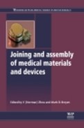
Thermal modelling of polymer welding is applied most easily when the process is predominantly one of diffusion at the surfaces and has minimal melt flow. Transmission laser welding is one such process. Models may be based on classical heat-flow equations for a specified joint design or using finite element methods. The models typically use details of the materials’ radiation absorption coefficient, thickness, reflectivity, melting point, density, heat capacity and thermal conductivity, whilst also taking into account the laser-beam profile, laser power and welding speed. Through analysis of the heat flow it is possible to generate the thermal history for all points in joint during the welding cycle. Thus it can provide the weld dimensions, the peak temperature and, with details of the materials’ mechanical properties, the residual stress remaining after welding can be estimated. Plate VII (see Plate VII between pages 300 and 301) shows a typical output from a finite element thermal model.5–8
13.3.2 Colour independence
As already described, the absorber used in transmission laser welding is often carbon black, which obviously affects the colour of the lower part being joined. Alternative absorbers are now available which have very little visible colour (Clearweld materials). They can be applied by liquid coating onto the joint surface or as an additive within the resin of the lower material. The additives are based on infrared absorbing dyes which have been tested for biocompatibility. They absorb the laser sources strongly and yet have very little absorption in visible ranges.
By using the Clearweld materials, completely transparent products can be laser welded, which is of particular importance in the medical industry where an initial indication of cleanliness and lack of contamination is important. An example of a laser-welded transparent medical device is shown in Fig. 13.3.9

13.4 Main welding parameters and effects
As with all plastics-welding processes, the three critical process parameters are temperature, time and pressure. In laser welding these are controlled by laser power, laser spot size, irradiation time (either fixed or moving systems), the presence of laser-absorber materials and clamping load.
The energy density used during welding combines the process parameters of temperature and time. It is determined by the laser power, the spot size at the joint, and the irradiation time (for fixed processes) or welding speed (for processes in which the part moves with respect to the laser):
or
If the energy density is too low then insufficient heating takes place and the material at the joint is not held at a high enough temperature for a sufficiently long time to form a strong weld. If the energy density is too high, then excess heating can degrade the polymer at the joint, resulting in porosity, or, in extreme cases, burning or charring of the polymer. Either case results in a weld of lower strength than the optimum. In practice, a relatively wide processing window can usually be found within which satisfactory welds can be produced. Typically laser-welding applications use an energy density within the range 0.1–2 J/mm2, although this will vary depending on the depth of melt required to ensure a satisfactory joint. Although the energy density can be used to characterise the welding process, it should be treated with caution. The conduction of heat away from the joint during welding means that using the same energy density will not necessarily result in the same quality of weld. For example, with a constant spot width, doubling the power will usually allow the speed to be more than doubled, whilst retaining the same performance from the weld.
The other factor affecting the amount of energy made available to the weld is the density and absorbance of the absorber present at the joint interface. A higher density of absorber will allow the weld to be made faster or with a lower-power laser.
The pressure applied is controlled using the clamping system. If the workpieces are not clamped together during welding, or if the pressure at the joint is insufficient, then the joint faces will not be in intimate contact. This will result in poor conduction of heat to the upper workpiece and limited interdiffusion of polymer chains across the joint interface.
Both effects result in a weld of lower strength than the optimum. Care is needed to ensure that a clamping load actually provides pressure at the joint. Typically, clamping pressure in the range 0.1–1 N/mm2 is used. If the workpieces bend under the clamping load in such a way that the joint is distorted then a poor weld can result. For this reason, it is often useful to have some compliance, for example an elastomeric element, in the clamping system.
13.5 Forms of equipment
A laser-welding system will typically consist of a laser source, a beam-delivery system and workpiece clamping or manipulation.
13.5.1 Laser types
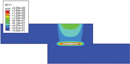
The main types of laser used for transmission laser welding are diode, Nd:YAG and fibre lasers in the wavelength range 0.8–1.1 µm. At longer IR wavelengths, CO2 and other lasers with a wavelength in the region of 2.0 µm, may be used for direct welding (Table 13.2).
Table 13.2
Laser types used for welding plastics
aEfficiency is the percentage of the electrical power consumed by the laser that is emitted in the beam.
bBeam quality is the ability to focus the beam to a small spot size with a high-energy density.
Nd:YAG
Nd:YAG lasers are widely used in industry for materials processing. High-power systems are bulky, but lower-power systems are relatively compact. Water cooling is usually required. The beam is transferred from the laser to the workpiece via an optical fibre. It is feasible to combine the beam from more than one laser to produce higher powers if required. The high-beam quality allows relatively small spot sizes to be produced.
Diode
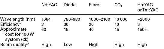
Diode lasers produce radiation at a wavelength of 780–980 nm. Water cooling is usually required. Their relatively low-beam quality means that they cannot be used to produce a spot size as small as Nd:YAG or fibre lasers. However, this is rarely a problem for plastics laser welding, where the relatively low purchase and running costs have attracted a great deal of interest. The beam may be delivered by an optical fibre, but the diode is sufficiently small and light that it is often feasible to use a direct system, in which the diode is included with a lens system in a single unit, typically ~150 × 150 × 300 mm. This unit can readily be mounted on a gantry system or robot arm to manipulate the beam (Fig. 13.4).
Fibre
Rare-earth doped fibre lasers typically supply a wavelength in the range 1000–2100 nm. In the field of materials processing, much interest has focused on wavelengths around 1100 nm to provide a direct replacement for Nd:YAG lasers, with equivalent beam quality, but greater efficiency. Systems are relatively compact and can be air cooled. In the field of plastics welding the use of fibre lasers has been demonstrated for a range of applications, including precision welding, films, textiles and larger moulded parts.
CO2 laser
CO2 lasers are widely use in industry for cutting plastics. High-power systems are bulky with gas-flow systems incorporated, but lower-power systems are relatively compact. The beam is transferred from the laser to the workpiece via mirrors. Focused spot sizes of less than 200 µm are available.
2.0 μm wavelength lasers
There are YAG and fibre lasers available emitting at a wavelength in the region of 2.0 μm. They are less commonly used than the other sources and more expensive. The beam can be delivered down a fibre optic, usually has good beam quality and can provide small focused spot sizes.
13.5.2 Beam delivery
The beam or workpiece manipulation equipment for laser welding will typically take one of the forms illustrated in Fig. 13.5, or a combination of one or more of these.
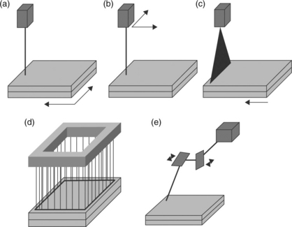
13.5 Laser beam and workpiece manipulation. (a) Moving workpiece. (b) Moving laser. (c) Curtain laser. (d) Simultaneous welding. (e) Scanning laser. (From Reference 10.)
Moving workpiece
With the laser fixed, the part can be manipulated to form a continuous weld. This can be achieved, for example, with rollers, or a single- or two-axis moving table. This type of system is relatively simple to set-up and programme, but would not normally be used if three-dimensional welds are required.
Moving laser
The optical system for a fibre delivered laser, or the laser head for a direct diode laser can be mounted on a variety of robotic systems. These range from simple two-axis gantry systems to multiple-axis robotic arms. The laser is manipulated around the part to be welded, potentially allowing complex, three-dimensional welds to be produced. To facilitate automatic production, it is feasible to combine a moving laser with a moving part, for example by using a rotating table to present different faces of a component to a laser mounted on a robot arm.
Curtain laser
The laser energy is spread into a line and then passed over the component, either by moving the laser or by moving the part. A mask is typically used to ensure that only the relevant areas of the component are exposed to the radiation. This is particularly suited to small components with a complex weld geometry. The process would usually be used only to produce two-dimensional welds. The welds may be completed very quickly with a single sweep of a line source.
Simultaneous welding
If a large number of identical welds is required then an array of diode lasers can be assembled in the shape of the weld to be produced. This is then used to irradiate the whole joint simultaneously, with a typical cycle time of 1–3 s. This approach is well suited to automated assembly. The equipment used is frequently based on ultrasonic welding equipment and this process is typically used in place of ultrasonic welding where a good cosmetic appearance is required or for components that are sensitive to vibration. Two- and three-dimensional welds can be produced. Since the entire joint is welded at the same time, this allows more collapse of the polymer at the joint, and therefore wider part tolerances.
The methods for simultaneous welding include development of light guides, fed by fibre-optic bundles, which are shaped to the item being welded. The light guide therefore provides both heating and clamping to the whole part at the same time.11
Scanning laser
The laser radiation is manipulated by a pair of orthogonal rotating mirrors over an area that may range from 50 mm × 50 mm up to approximately 1000 mm × 1000 mm. In general, a larger working area implies a longer working distance and a larger spot size. It is possible to co-ordinate a number of scanning systems to give a larger working area. In general, only two-dimensional welds can be produced.
Repeatedly scanning the laser at high speed over the same path can be used to give quasi-simultaneous welding. As for simultaneous welding, this heats the entire joint area at the same time, allowing more collapse of the material in the joint and potentially allowing wider tolerances.
An alternative approach is to direct a scanning beam onto a mirror surrounding the weld line. This has been carried out using a cone-shaped mirror surrounding a cylindrical part, allowing tube tips or small round components to be welded simultaneously.12
13.5.3 Clamping
A wide variety of clamping systems have been used for transmission laser welding. They are mostly variants of the two systems illustrated in Fig. 13.6.
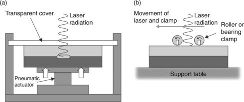
13.6 Clamping systems for through-transmission laser welding (a) Fixed clamp. (b) Moving clamp. (From Reference 10.)
Variants of the fixed clamp include systems using mechanical fastenings, rather than an actuator, to apply a load. In the simplest variant, if the part design allows it, a bolt can be passed through the workpiece to apply the load. The transparent cover must be rigid enough to provide the clamping pressure. Thick acrylic or plain plate glass can be used. Borosilicate glass is less vulnerable to thermal shocks during welding, but more expensive. For welding of high-temperature polymers, quartz glass may be used. In all cases it is important to ensure that suitable safety precautions are taken to avoid the risk of injury if the transparent cover breaks while it is under load.
The moving clamp can use bearings, rollers or a simple sliding shoe to apply a clamping load. Because the load is applied only at the point where the joint is irradiated, clamping loads may be much lower when a moving clamp is used. There is therefore less risk of distorting the workpiece, and equipment can be less bulky. This is particularly advantageous for large components, where application of a suitable clamping pressure to a large area can require large loads.
Welding in a nip between two rollers is typically used to weld two flexible materials together or a flexible film to a rigid base. The laser beam is directed towards the nip between the rollers and positioned to heat both internal surfaces of the joint just before they are pressed together. Very high-speed processing (over 500 m/min) has been demonstrated using this technique.
Another method of applying force at the point of heating, a variation of the moving clamp, is to transmit the laser beam through a ball-shaped transmissive clamp. The ball rolls in an air bearing socket. The air flow also helps to keep it clean and maintain a consistent transmission of energy. Such a clamp has been used successfully with 3-D robotic-welding equipment for complex-shaped parts.12
13.6 Weldable materials
This section describes the range of plastics and textiles that can be welded using the laser process, and the material characteristics that are important. Dissimilar material combinations are also considered.
13.6.1 Weldable plastics
A wide range of plastics can be welded using laser-welding procedures. The process is tolerant of a wide range to melting temperatures, a wide range of melt viscosities and of materials that readily oxidise in air. This is because the temperature at the joint can be readily controlled, the melt zone is of minimal volume, and is generally trapped at the joint line by surrounding solid material. Material in a variety of forms can also be readily processed, including film and sheet, moulded parts, elastomers, fabrics and dissimilar combinations of those types.
The main limitation in materials selection is the presence of dark colours and opaque additives. It must be remembered that for transmission laser welding, at least one of the parts must transmit a proportion of the laser energy. This therefore limits the use of carbon-black pigments and other opaque pigments such as titanium dioxide to the side of the joint away from the laser. This is not the case in direct laser welding.
13.6.2 Transmission properties
The transmission properties of plastics vary with the type of polymer, the crystallinity and the additive or pigment content. It has already been stated that for transmission laser welding it is preferable for the part closest to the laser to be more than 10% transmissive. Transmission measurement is carried out using a calorimeter to measure a laser pulse energy directly and then with the test material between the sensor and the laser source. The pulse energy measured in these two cases is compared. A more detailed measurement includes the reflection of energy at the surface, which can be significant for some materials and will also limit the energy available to the weld.
The spherulites in semi-crystalline plastics and any particulate or fibre additives lead to scattering of the laser beam. This leads to a reduction in beam intensity at the weld interface. Measurements can be used to indicate the size of such effects to allow the beam shape and process parameters to be controlled accordingly.
Typically amorphous plastics (e.g. polycarbonate, polymethylmethacrylate, polystyrene) with minimal additive content can be welded in thicknesses up to at least 100 mm. Semi-crystalline plastics (e.g. polyethylene, nylon) are suitable for laser welding up to a thickness of 10 mm. Some materials, such as polyetheretherketone (PEEK), can only be welded when the thickness is less than 1 mm using transmission laser welding. Glass-fibre additives tend to increase the beam scattering, but do not prevent laser transmission. Other additives such as carbon-black or titanium-dioxide pigments will block or reflect the beam, and prevent welding.
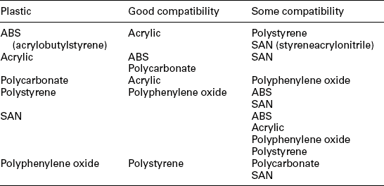
13.6.3 Compatible combinations
In general, only similar plastics can be welded together. However there are some combinations of different plastics that are compatible with each other. Compatible combinations are shown in Table 13.3.
13.6.4 Textiles
Fabrics are most commonly joined by stitching, a highly labour-intensive process that renders production cost-prohibitive in many parts of the world. It also makes holes in the fabric, which impairs the strength of the resulting seam and limits the performance of seams that need to be sealed.
The principal advantages of laser welding for joining textiles include high production rates; sealed seams; no melting of external fabric texture; single-sided access so welds can be produced beneath other layers of fabric; seam flexibility; and robotic manipulation for automated joining.
Applications such as inflatable product construction, sealed mattress assembly, medical furniture and protective clothing (Fig. 13.7) have been studied, with successful demonstration of representative seams that meet the performance requirements of the applications.13 Laser welding of flexible implantable products has also been developed. This is for the construction of vascular grafts, where polyester fabric can be joined to support stents using a cost-effective, automated process.14

The laser-welding procedure used for textiles is generally based on the Clearweld method of transmission laser welding, but direct welding using either diode or CO2 laser sources is also feasible.
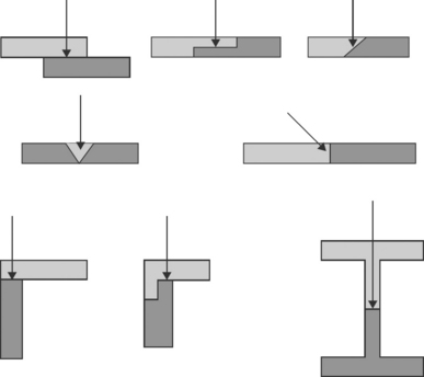
13.7 Joint designs
A selection of successful joint designs suitable for transmission laser welding is shown in Fig. 13.8. In general, it must be ensured that the energy reaching the joint interface is sufficient for melting the interface material without overheating the material on the outer surface and, as far as possible, evenly distributed at the interface. Extra care may be required to ensure even distribution of energy for interfaces angled to the beam direction or for complex-shaped parts that have different thicknesses along the joint line. Parts must be well fitting. A surface roughness less than 50 μm may be used as a general rule of thumb. Joints are often designed to be self-aligning, may incorporate a snap-fit to hold parts in place for welding or can be sized to allow self-clamping. As an example, tubes may be arranged to have an interference fit to allow self-clamping.15
13.8 Monitoring and quality control
Laser welding is unique in the precision with which the location and amount of energy applied can be controlled. To take advantage of this potential, a rapid and accurate monitoring method is required.
Monitoring may be applied for a number of reasons, to confirm that various stages of the process have occurred, as well as to assess the quality of the weld:
• confirmation that the infrared absorber is applied correctly to parts before welding;
• indication that the parts are in contact during process;
• indication that weld heating is being carried out and control of temperature;
• indication that the parts are in contact after completion;
• indication that the weld has been achieved after completion;
• indication that the weld quality and strength are satisfactory.
Monitoring methods can give information for most of these points with varying degrees of confidence; however, it must be noted that complete quality and weld strength assurance can only be achieved with destructive testing.
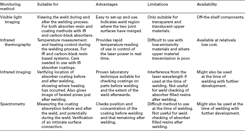
Monitoring of other polymer-joining methods is generally carried out by monitoring process parameters, such as energy utilised and displacement. These can also be applied with laser welding, but the process is also well suited to the use of optical methods, such as infrared thermography. This, and other optical methods, are summarised in Table 13.4.16
13.9 Applications
Typical medical applications that have been considered or put into production are summarised below.
13.9.1 Microfluidic devices and microelectromechnical systems (MEMS)
Laser welding procedures for microfluidic devices have been developed and described in detail.17,18 Smaller-scale biological analysis or chemical micro-reactors (e.g. 50 × 25 mm platforms) are being developed in plastics so that smaller samples can be used or sample processing can be carried out more cheaply. Typically these have been made of glass with small fluid channels (~100 μm wide), and sealed with adhesives. In many applications there is a drive to mass produce the units and hence a need for lower-cost materials and manufacturing procedures. Use of plastics is being considered widely and joining methods are needed to provide the precision, reproducibility and speed for mass production. Laser welding is well suited to meet these challenges and can be used to seal round the channels or round electronic connections or devices. Different processing options have been suggested for the manufacture of micro devices. These include using line beam as a curtain of energy over the whole part either with or without a mask, or by scanning a small spot source around individual channels. Both can provide rapid manufacture with high quality and reliability of sealing and in particular without damage to the channels in the units as a result of the welding process. The two methods of processing can be applied to different application areas or product designs.
13.9.2 Catheters and small-diameter tubing
Butt joints between tube ends, lap joints between tubes of different diameters, for tip attachments and for balloon sealing and longitudinal tube welding have all been demonstrated using laser welding on a range of small-diameter tubes.19 A balloon catheter is composed of a polymer balloon that is attached to a polymer shaft at two points called the distal and proximal bonds. The bonds have been conventionally made using cyanoacrylate or UV curing adhesive; however, with performance requirements of bond strength, flexibility, profile and manufacturing costs these bonds are increasingly being made by welding using laser, RF and Hot Jaw methods. Laser welding has typically been carried out using a CO2 laser to provide direct heating in combination with shrink polymer tubing to support the materials. The position and volume of melting can be controlled using rotating supports, optical scanning of the laser, and control of the temperature and time of heating. It is possible to shape the tip and balloon overlap regions using this processing. More recently, alternative techniques using selective laser absorbers and shorter wavelength diode and fibre lasers have been developed and applied to catheters and tubing. An example of a longitudinal seam weld is shown in Plate VIII (see Plate VIII between pages 300 and 301). In this case an infrared absorbent coating was applied along the edge surfaces to be joined, and a laser beam much larger than the joint region was directed over the whole joint region, providing selective heating only where the laser and the absorber coincided at the joint.

13.9.3 Textiles – vascular graft
As already discussed, laser processing can be used to join textiles. This procedure has been applied in the joining of vascular grafts, where nitinol stent wire rings must be attached to a polyester fabric tube to hold the tube open. An abdominal aortic aneurysm (AAA) is a type of cardiovascular disease, a life-threatening condition that occurs when a section of the abdominal aorta, the body’s main circulatory vessel, weakens and bulges outwards, as shown in Fig. 13.9, to form a fragile, balloon-like swelling which is prone to rupture.
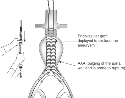
13.9 Schematic illustration of the AAA along with the Anaconda endovascular device manufactured by Vascutek Ltd. (Picture courtesy of Vascutek Ltd.)
Currently, weaving is used to produce the textile graft material, and hand-sewing is used to add the Nitinol ring-stents to the graft, which is very complex and highly labour intensive with quality dependent on the operator. Some of the joining techniques that have been considered in place of manual stitching are listed below:
After a series of preliminary feasibility trials, laser welding showed potential as a novel, alternative manufacturing technique to assemble the stent-grafts.
The laser-welding process consists mainly of three stages:
(i) application of Clearweld laser absorber dye at the interface of the two materials being welded;
(ii) assembly of the seam and application of clamping pressure;
(iii) irradiation of the seam with a near infrared laser (940 nm) to melt the material where the absorber has been applied and create a permanent weld at the interface between the two materials being joined.
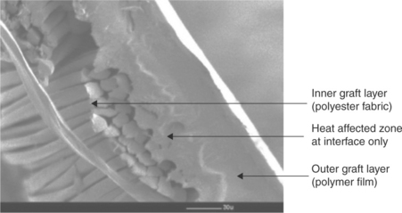
The main purpose of sewing the Nitinol ring-stents to the graft fabric is to hold it securely in place to keep the graft fabric tube open at all times. Using the laser-welding technique, this is achieved by introducing an outer film layer and welding it to the inner polyester graft fabric thereby sandwiching the rings in between the two layers and securely holding it in place. The heat-affected zone generated during the laser-welding process is localised and restricted to the interface between the two layers (see Fig. 13.10) and hence the Nitinol ring-stents are not affected by the heat generated. A very thin layer of polymer is melted in each graft layer and the application of clamping pressure brings the melted fibres in contact. The clamping pressure is maintained as the melted fibres cool and solidifies to produce a permanent weld.
Laser welding using polyester fabric on polymer film configuration proved to be ideal to provide some fibres melt into the film but not through the full thickness. During tensile tests, most of the samples failed in the parent material rather than at weld location or along edge of the weld, indicating a strong weld. Furthermore, this material combination resulted in minimal bulk (thickness) at the joint location and hence was suitable for use in the final-product configuration.
It is clear as a result of extensive feasibility studies that laser welding (using the Clearweld process) could potentially replace hand-sewing as it offers many functional advantages over conventional joining techniques, thereby reducing production times, costs and improving the quality and durability of the products.20
Laser welding has also been considered for other medical-textiles applications such as seam sealing of gowns, manufacture of dressings and for making sealed seams in hospital furniture reducing the chance of transferred infection by enabling greater cleanliness around the seams.
13.9.4 Sealed bags and inflatable devices
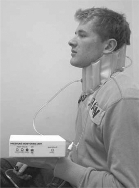
Continuous seam sealing using laser welding has been applied to thin films to create products that can be inflated or used as containers. Examples include an inflatable neck brace and ostomy bags. More detail about the neck-brace application is provided below10 and serves to demonstrate application to inflatable devices.
The Royal National Hospital for Rheumatic Disease (RNHRD) in Bath, UK, has developed the concept of an inflatable brace for the immobilisation of neck injuries. This can be inflated to a high pressure when a high level of support is required, for example when the patient is travelling. The pressure can be reduced when greater mobility is required, for example while eating. The material selected for the brace was Hytrel®, a thermoplastic polyester elastomer from DuPont™. For simplicity, two sheets were welded together, forming a number of interconnected inflatable chambers. The brace could be customised for each patient. This steered the choice of welding process towards laser welding, using equipment that could be rapidly programmed to produce different sizes tailored to individual patient measurements. A moulded lug for inflation was welded directly to the Hytrel® sheet. The processing used a diode-laser system mounted above a two-axis CNC manipulating table. The profile of the welds to be made were defined by the CNC table, and could easily be adjusted. Prototype parts have been successfully tested, and one is shown in Fig. 13.11.
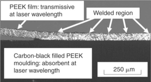
13.9.5 Polyetheretherketone (PEEK) film and implants
Polyetheretherketone is an engineering polymer with high strength and stability in harsh chemical and high-temperature environments. It also has a high wear resistance, and low coefficient of friction. It has a high melting point of 343 °C and typically a highly crystalline structure that limits laser transmission to approximately 1 mm in thickness. PEEK-OPTIMA®, supplied by Invibio®, is a medical grade for use in long-term implanted medical devices, with potential for packaging of electronic components. When assembling such components it is necessary to prepare hermetic joints.
There is therefore considerable interest in the use of welding processes for part assembly. Laser processes are suited to welding PEEK in film and thin moulded forms (< 1 mm) using transmission laser welding (Fig. 13.12). For thicker PEEK products, direct laser welding can be used that does not rely on transmission of the laser through the highly crystalline polymer.
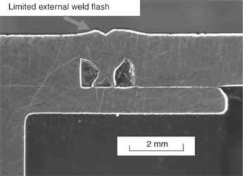
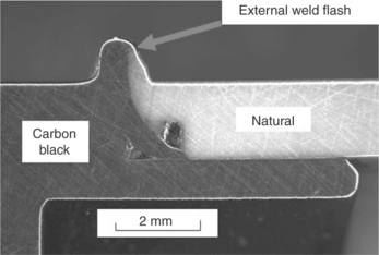
Direct laser welding has been demonstrated for sealing of cylindrical test cylinders, 24 mm in diameter, 16 mm tall, and with a wall thickness of 3 mm. Equipment was designed to spin the part underneath a diode laser to provide simultaneous heating of the circumference of the joint. A WeldControl system was used to monitor the weld temperature and provide feedback to adjust the laser power and maintain the weld temperature at the required level just above the melting point of the plastic. Excellent welds were produced in black to black and black to natural samples. The weld time in each case was approximately 10 s. Figures 13.13 and 13.14 show micrographs of cross-sections through the welds. A bubble test showed good hermeticity in the welds.
13.10 References
1. Jones, I.A., Taylor, N.S. High speed welding of plastics using lasers. ANTEC 1994, conference proceedings – Society of Plastics Engineers, San Francisco, May, 1994.
2. Kurusaki, Y., Matayoshi, T., Sato, K. Overlap welding of thermoplastic parts without causing surface damage by using a CO2 laser. ANTEC 2003, conference proceedings – Society of Plastics Engineers, Nashville, May, 2003.
3. Herfurth, H., Ehlers, B., Heinemann, S., Haensch, D. New approaches in plastic welding with diode lasers. Laser Materials Processing. ICALEO ’99, conference proceedings, San Diego, November, 1999.
4. Jones, I.A., Taylor, N.S., Sallavanti, R., Griffiths, J. Use of infrared dyes for transmission laser welding of plastics. ANTEC 2000, conference proceedings – Society of Plastics Engineers, Orlando, May, 2000.
5. Kennish, Y.C., Shercliffe, H.R., McGrath, G.C. Heat flow model for laser welding of polymers. ANTEC 2002, conference proceedings – Society of Plastics Engineers, San Francisco, May, 2002.
6. Grewell, D., Benatar, A. Modelling heat flow for a moving heat source to describe scan micro-laser welding. ANTEC 2003, conference proceedings – Society of Plastics Engineers, Nashville, May, 2003.
7. Abed, S., Knapp, W., Ghorbel, E., Agrebi, K., Laurens, P. Thermal modelling of the laser welding of polypropylene. Lasers in Manufacturing 2003, proceedings of 2nd International WLT Conference, Munich, June, 2003.
8. Jones, I.A., Olden, E. A thermal model for transmission laser welding of thermoplastic polymer, 2000. [TWI Members report 708/2000, July].
9. Klein, R., McGrath, G. Creating transparent laser weldings on thermoplastic components. Joining Plastics 2006, conference proceedings, London, April, 2006.
10. Warwick, C.M., Gordon, M. Application studies using through-transmission laser welding of polymers. Proc. Joining Plastics 2006, 25–26 April. NPL, London, 2006.
11. Caldwell, S., Rooney, P. Design flexibility in waveguides and lightpipes for TTIr plastics welding. ANTEC 2004, conference proceedings – Society of Plastics Engineers, Chicago, May, 2004.
12. www.leister.com.
13. Jones, I.A., Improving productivity and quality with laser seaming of fabrics. Technical Textiles International, 2005:35. [May].
14. Patil, A., Jones, I., Ashton, T., Tavakoli, M. Investigation into novel joining techniques for rapid and automated manufacturing of a new generation of endovascular grafts. Proceedings of Health Technologies KTN/University of Brighton Annual Conference, 3 April, 2008.
15. Kirkland, T.R. Practical joint designs for laser welding of thermoplastics. ANTEC 2004, conference proceedings – Society of Plastics Engineers, Chicago, May, 2004.
16. Jones, I.A., Rudlin, J. Process monitoring methods in laser welding of plastics. Joining Plastics 2006, conference proceedings, London, April, 2006.
17. Jones, I.A., Loyo-Maldonado, V. Comparison of laser welding methods for microfluidic devices. Joining Plastics 2010 – 2nd DVS/WJS Conference, Dusseldorf, 2 November, 2010.
18. Chen, J.-W., Zykbo, J.M. Diode laser bonding of planar microfluidic devices, MOEMS, bioMEMS, diagnostic chips and microarrays. Proc. SPIE. 2005; 5718:92–98.
19. Flanagan, A.J. Laser welding of balloon catheters. Proc. SPIE. 2003; 4876:517.
20. Patil, A., Jones, I., Ashton, T. New manufacturing methods for vascular grafts using laser welding and laser cutting techniques. Joining Plastics 2010 – 2nd DVS/WJS Conference, Dusseldorf, November, 2010.