
Micro-welding of shape-memory alloys
Abstract:
This chapter discusses the challenges in the joining of Nitinol (i.e. NiTi alloys) shape-memory alloys (SMAs) which are becoming increasingly popular in medical-device applications due to their unique shape-memory effect and pseudoelastic (i.e. superelastic) functional properties. The chapter starts by providing a brief introduction to the properties of SMAs followed by a review of how different micro-welding techniques affect the alloy microstructure and properties. Fundamentals for key micro-welding processes used in joining Nitinol SMAs are detailed, including resistance and laser micro-welding (i.e. RMW and LMW).
5.1 Introduction
The unique properties of shape-memory alloys (SMAs) have resulted in numerous applications, including fasteners, actuators, wear prevention and most importantly biomedical devices.1 As the knowledge base and processing methods of these materials continue to evolve, many more potential applications can be realized. In particular, there is ever increasing interest and implementation of SMA in biomedical applications. Their excellent biocompatibility coupled with good strength and ductility has made them an ideal material for implantable medical devices. Temperature-dependent characteristics of their functional properties, which are disadvantageous in certain applications, are insignificant in implantable medical devices due to the temperature stability maintained by the human body (i.e. 37 °C). Furthermore, specific surface treatments have shown to greatly improve SMA biocompatibility.2
In many cases, medical-device fabrication procedures require microwelding techniques. An example of this is shown in Fig. 5.1 where microscopic forceps utilized in endoscopic brain surgery is connected to 0.63 mm wire using laser welding.3 However, joining (i.e. welding, brazing and soldering) of Nitinol is generally difficult, which in turn limits flexibility in the design and fabrication of Nitinol devices and hence impedes high-volume commercialization of the alloys. This is further complicated when working on small-scale products, such as those implemented in medical-device components. This chapter starts by providing a brief introduction to the properties of SMAs. Fundamentals for key micro-welding processes are detailed, including resistance and laser micro-welding. Finally (LMW), a review of current challenges faced with welding Nitinol is provided.
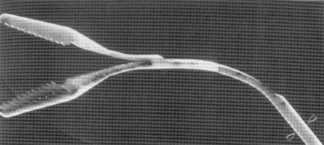
5.1 Laser-welded microforceps made from Nitinol. Source: Reprinted with permission of ASM International. All rights reserved. www.asminternational.org.3
5.2 Fundamentals of Nitinol shape-memory alloys
The shape-memory and pseudoelastic properties of near equatomic Nitinol were discovered in 1963 by Beuhler et al.5 Similar effects were discovered earlier in other alloys;6,7 however, the superior mechanical and functional properties of NiTi alloys has led to greater popularity. As the fundamental understanding of Nitinol’s mechanical behaviour improved, these alloys started to become commercially available in the 1970s. To date, Nitinol alloys provide the best combination of shape-memory material properties for commercial applications.1 They particularly excel in the medical-device industry due to the excellent biocompatibility, where they are used for bone brackets, surgical staples, vascular stents, orthodontic arch wires and many more applications.14
The composition required to form Nitinol SMAs can be determined using a binary NiTi phase diagram, shown in Fig. 5.2.8 The NiTi phase is restricted to the central region of the diagram between the Ti2Ni and TiNi3 phases, near equiatomic composition. Not shown on this diagram is the metastable Ti3Ni4 intermediate phase between NiTi and TiNi3. This Ti3Ni4 phase is essential in altering the functional properties of the Nitinol SMA. At lower aging temperatures the Ti3Ni4 phase appears while at higher aging temperatures the TiNi3 phase is more stable.9
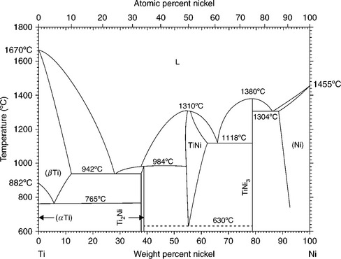
5.2 NiTi phase diagram. (L in the figure refers to liquid.) Source: Reprinted with permission of ASM International. All rights reserved. www.asminternational.org.8
Mechanisms responsible for Nitinol’s functional properties are closely linked to diffusionless solid–solid martensitic phase transformations. SMA phase transformations typically occur in a metastable solid state. Phase transformations can be induced by either temperature change or mechanical deformation. During transformation the austenite (i.e. B2 phase) transforms into martensite (i.e. B19′). Temperatures and stresses required to induce phase transformation are largely dependent on the alloys’ chemical composition and previous thermomechanical processing. The following sections describe the temperature- and stress-induced transformations and the associated shape memory and pseudoelastic properties, respectively.
5.2.1 Temperature-induced transformation
Temperature-induced transformation in SMAs are typically characterized by four distinct temperatures, including austenite start (As) and austenite finish (Af) during heating and martensite start (Ms) and martensite finish (Mf) during cooling. As and Af indicate the start and finish of martensite to austenite phase transformation, while Ms and Mf describe the reverse austenite to martensite transformation. Temperatures are typically identified utilizing a differential scanning calorimeter which captures the endothermic and exothermic events during phase transformation. A schematic showing the volume fraction transformed as a function of temperature is shown in Fig. 5.3.10 For Nitinol, transformation temperatures typically range from −150 °C to 150 °C, while the overall hysteresis of transformation are in the range of 10–50 °C.
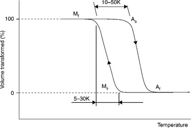
5.3 Schematic of the volume transformed as a function of temperature. Source: Copyright (2001) Wiley. Used with permission from Van Humbeeck, J., Shape memory alloys: a material and a technology, Advanced Engineering Materials, John Wiley & Sons.10
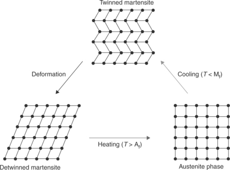
The ability Nitinol to undergo solid–solid phase transformation enables the material to exhibit a phenomenon known as shape-memory effect (SME). schematically detailed in Fig. 5.4. During this cycle the initial parent material is brought to a temperature below Ms. At this temperature detwinning of the martensite phase accommodates deformation and maintains the altered shape. Subsequent heating to above Af would result in phase transformation and recovery of its original shape and hence its ability to remember a shape.
5.2.2 Stress–strain curve and pseudoelasticity
The non-linear stress–strain behaviour of SMAs is unlike other common metallic engineering materials. Figure 5.5a shows a typical pseudoelastic stress–strain curve where the sample is loaded to failure. This stress–strain curve consists of three distinct deformation zones: elastic (region 1), pseudoelastic (region 2) and plastic deformation (region 3). At temperatures above Af, the pseudoelastic properties of Nitinol enable it to be strained beyond the linear elastic (region 1) portion on a stress–strain curve while undergoing stress-induced phase transformation. The applied stress transforms the austenite parent phase to martensite which is termed stress-induced martensite (SIM). Upon removal of stress within region 2 most of the mechanically induced martensite reverts back to austenite, as shown in Fig. 5.5b. The magnitude of near-perfect pseudoelastic strain for Nitinol can reach 8% in polycrystalline materials.10 Straining beyond the pseudoelastic region results in the plastic deformation of martensite until full fracture occurs.
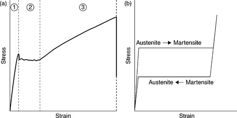
5.5 Schematic of a typical stress–strain curve for pseudoelastic NiTi alloy: (a) stress–strain curve until fracture and (b) loading–unloading curve.10
5.3 Micro-welding of NiTi
With increased demands for finer and more complex devices, advancement in effective processing methods becomes necessary. Hence, the development of effective micro-welding of NiTi is an integral part of the manufacturing of Nitinol-based devices. Welding processes commonly result in localized changes in the welded regions, yielding properties that differ from that of the original material. These changes become even more of a concern in SMAs because not only are their mechanical properties altered but also their functional properties. Strength reduction, inclusions of intermetallic compounds, altered pseudoelastic and SMEs are all examples of how Nitinol can be affected by welding.5–13 Micro-resistance spot welding (MRSW) and LMW of crossed-wires are two commonly used welding processes for interconnection and component assembly for miniature medical devices, such as pacemakers.14 Each of these processes can affect differently the aforementioned properties of Nitinol. Furthermore, their respective process parameters can greatly influence the extent of altered properties.6 The following sections detail the effect of laser and resistance micro-welding (RMW) procedures on the mechanical and metallurgical behaviours of welded crossed Nitinol wires. Details on fundamentals for both welding procedures can be reviewed in Chapter 5 and Reference 11.
5.3.1 Laser micro-welding
During LMW peak temperatures in the weld metal typically surpass the material melting point resulting in a molten metal pool which subsequently solidifies upon removal of lasing energy. Often pulsing methods are implemented to aid in minimizing the heat-affected regions during the welding of miniature components. However, thermomechanical properties of the re-molten material can still greatly differ compared with the base material.
Effects of laser welding on mechanical performance
The majority of SMAs in application are subjected to loading to the pseudoelastic loading stress of the material. Therefore the failure stress is required to be above the pseudoelastic stress. However, depending on laser-welding processing parameters the maximum tensile stress can either be above or below the maximum strength. This process parameter dependence is shown in Fig. 5.6, which shows engineering stress–strain curves of traverse pulsed Nd:YAG laser-welded tensile specimens for varying peak power (0.6–0.9 kW) as compared to the Nitinol base material.12 Typical pseudoelastic behaviour is indicated by a flat region (plateau) after linear elastic straining when a 290 MPa plateau stress is achieved. Beyond the plateau stress, plastic deformation of martensite occurs and load increases due to strain hardening followed by material failure. Laser-welded material often have reduced failure stress and ductility compared with the base metal. However, failure stresses obtained with high enough peak power surpass the pseudoelastic region and are acceptable for SMA applications (Fig. 5.6).
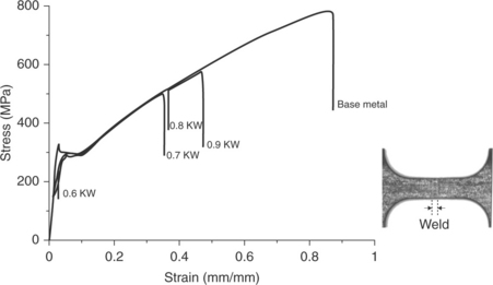
5.6 Representative tensile curves for varying peak power input for 10 pps frequency and 5 ms pulse time.12
Although SIM transformation (austenite→ martensite) occurs in a traverse weld specimen,1,9 the weld zones experience an irreversible initial yielding. This is shown in Fig. 5.7,12 which details the elastic to pseudoelastic deformation. The initial plateau indicates yielding in the welded region, while the second plateau is the SIM transformation in the base metal (BM) stress–strain curve (Fig. 5.6). Furthermore, process parameters directly affect the magnitude of yielding, which became more pronounced with increasing peak power. Reasons for this change will be detailed in the following section. However, it is crucial that the mechanism of deformation and its correlation to process parameters is accounted for prior to implementation of a welded SMA device.
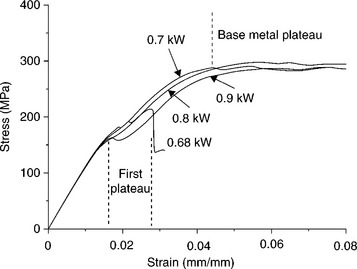
5.7 Detailed view of multiple plateaus in processed samples.12
For most welded SMA devices the weld metal only accounts for a fraction of total material. As such, it is more realistic to test weld tensile samples that consist of both unaffected base metal and weld metal. Figure 5.8 shows a schematic of such a sample that is at the different stages of deformation experienced during loading (i.e. see Fig. 5.7). During loading, the transverse tensile coupon induces stress in both the base and weld metal. Upon initial tensile loading, both regions experience elastic deformation until a critical stress is reached where the onset of the initial plateau occurs. Local yielding experienced within the welded region, illustrated in Fig. 5.8b, results in the formation of the initial plateau. Additional straining then induces further elastic deformation of the remaining unaffected gauge length followed by SIM transformation (Fig. 5.8c). Hence the presence of multiple plateaus results from different deformation mechanisms occurring in the weld and base metal. Amplification of the first plateau is directly related to the increasing peak power since increasing peak power results in a larger weld width. Accordingly, a larger volume within the gauge length undergoes local deformation. This altered mechanical performance must be accounted for during the design of welded SMA devices.
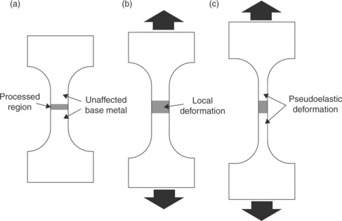
5.8 Schematic of deformation occurring in the tests presented in Fig. 5.7: (a) before straining; (b) initial plateau and (c) base metal plateau.
Effects of laser micro-welding on NiTi microstructure and phase transformation
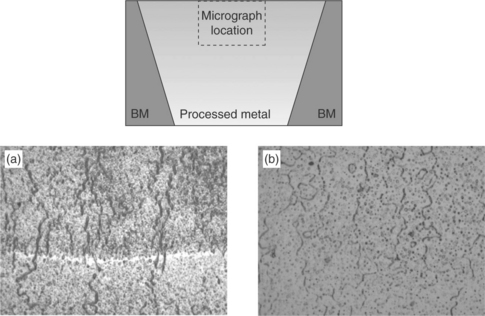
Re-melting due to laser welding significantly alters base metal microstructure, which for most SMAs is responsible for the change in mechanical properties. Specifically, laser welding causes dendrite formation, grain coarsening and segregation of intermetallic (IMC) compound at grain boundaries. These phenomena are observed in Fig. 5.9, which shows Optical micrographs for pulsed Nd:YAG laser-welded Nitinol. The base metal (Fig. 5.9b) consists of a homogeneous single-phase microstructure, with relatively large NiTi grains (about 20–40 µm). Similar base-metal microstructure is observed near the interface of the re-solidified fusion zone, shown in Fig. 5.9d. Columnar dendritic growth occurs along the solidification interface with finely dispersed IMC within the fusion zone. These IMCs are further defined in Fig. 5.9b where the use polarized light highlights their location.

5.9 Cross-section of samples generated at 0.6 kW, 10 pps showing overall cross-section under (a) white and (b) polarized light and high magnification of (c) base material and (d) re-solidified interface.
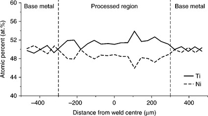
Depending on the SMA alloy composition and welding parameters, IMCs in the weld material can be either Ti-rich (i.e. Ti2Ni) or Ni-rich (Ni3Ti). Ti2Ni is an intermetallic present in the binary NiTi phase diagram (Fig. 5.2), it is most stable in Ti-rich alloys/regions. When the re-solidified material is in the Ni-rich domain, Ni-rich IMCs form (i.e. Ni3Ti). However, the near equiatomic composition of Nitinol coupled with ability of high power-density laser-welding processes to locally vaporize constituents, IMCs and composition in the weld metal can vary greatly. Furthermore, in NiTi alloys Ni is most susceptible to vaporization since it is most volatile, having the highest vapour pressure. An example of changes in Ni content is given in Fig. 5.10, where an energy dispersion spectrum (EDS) scan measures lower Ni concentrations in the weld metal. As such Ti-rich IMCs can become stable in Ni-rich alloys.
The concentration of IMC is greatly influenced by the laser-welding process parameters, which is also directly correlated to the mechanical performance. Specifically, it has been shown that high peak powers can result in reduced concentrations of IMC.12 This can be observed in Fig. 5.11 which details the microstructures near the top of the welded region for 0.6 and 0.9 kW peak-power parameters. Each condition exhibits varying amounts of sub-micron Ti2Ni segregation. The 0.6 kW weld shows a high density of continuous intergranular segregation compared to that of the 0.9 kW weld. These segregated phases act as preferential sites in the weld metal where failure initiates and/or propagates. As such, higher segregation concentrations may result in premature failure as observed for the 0.6 kW weld in Fig. 5.6. Specifically, the densely segregated condition observed with a peak laser power of 0.6 kW lead to premature failure, whereas with 0.9 kW the joint performed better and the weld strength surpassed the pseudoelastic plateau stress.
5.11 Fusion zone microstructure at the top of weld-fusion zone for (a) 0.6 kW and (b) 0.9 kW peak-power conditions. BM, base metal.
As a consequence of preferential Ni vaporization, the thermal properties of Nitinol are greatly affected. Sensitivity to composition change has been shown to be severe in the nickel-rich alloys, with changes of only 1 at% altering Ms temperature by as much as 250 °C.9 As Nitinol Ni content decreases with high power-density laser-welding processes, there is an increase transformation temperatures. This is observed in DSC curves shown in Fig. 5.12, where the laser-welded material exhibit a high temperature compared with base-metal phase transformation, which is primarily induced by Ni vaporization. However, if power densities during laser welding are kept to a minimal and vaporization is not induced, then transformation temperature can decrease as shown in Fig. 5.13.13 This decrease is due to the recrystallization of the microstructure, which removes transformation impeding dislocations. As such, change in weld transformation temperature must be considered in medical-device application.
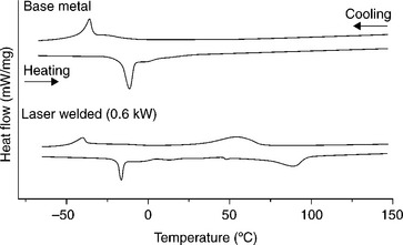

5.13 DSC scans for base (left) and CO2 laser-welded metal (right) showing decrease in exothermic martensite phase transformation peak. Source: With kind permission from Springer Science + Business Media: Metallurgical Materials Transactions A, Effects of CO2 welding on the shape memory and corrosion characteristics of TiNl alloys, 32(3), 2001, p. 569, Hsu, Y. T., Wang, Y. R., Wu, S. K., Chen, C., Figure 4.13
5.3.2 Resistance micro-welding
Like laser welding, MRSW can affect the local functional properties of Nitinol. Modifications to base-metal transformation behaviours15,16 and previous strengthening heat treatments17,18 have been shown to occur during the application of thermomechanical processing. Similar thermomechanical processing is experienced during MRSW. During MRSW, metallurgical bonds form between two faying surfaces using heat generated by the resistance to passage of electric current through the workpieces. This involves the coordinated application of electric current and mechanical force of specified magnitude and duration.19 The induced changes to Nitintol alloys must be thoroughly understood in order to refine the protocol for achieving functional welds. This section describes these effects on a crossed-wire configuration of fine Nitinol wire.
Mechanical properties and failure mechanism
Compared with the base-metal strength, MRSW welds have a considerably lower failure force, known as joint breaking force (JBF). Figure 5.14 shows the effects of welding current on JBF and set-down for MRSW of 400 µm diameter Nitinol wire.14 Although Joint strength increases sharply with current, only a maximum JBF of 18 N was achieved with 200A current. The 18 N JBF is only a fraction of the 70 N breaking force of base metal. At higher currents, over welding and degradation to joint strength occur due to the introduction of weld defects.
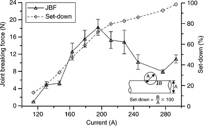
5.14 Effects of welding current on joint breaking force (JBF) and set-down. Source: With kind permission from Springer Science + Business Media: Metallurgical Materials Transactions A, Resistance microwelding of Ti-55.8 wt pct Ni Nitinol wires and the effects of pseudoelasticity, 43(8), 2012, p. 2969, Tam, B., Pequegnat, A., Khan, M.I., Zhou, Y., Figure 6.14
Joint strength and fracture mechanism of MRSW of crossed NiTi strongly influence the weld morphology. Figure 5.15 shows the fracture surface of welds.14 At low currents fracture occurs through the bond interface (Fig. 5.15a) in a brittle fracture mode, which is indicated by the relatively smooth surface (Fig. 5.15b). Joint strength gradually increases due to improved bond strength as set-down increases coupled with solid-state bonding. Higher currents also result in dimpled ductile fracture morphology (Fig. 5.15d). As the JBF increases due to the larger bond area the HAZ becomes increasingly softer due to recrystallization until eventually failure begins to occur in the HAZ.

5.15 Fracture surfaces of joint welded at different welding currents: 145 A (a and b), 195 A (c to e) and 245 A (f). Source: With kind permission from Springer Science + Business Media: Metallurgical Materials Transactions A, Resistance microwelding of Ti-55.8 wt pct Ni nitinol wires and the effects of pseudoelasticity, 43(8), 2012, p. 2969, Tam, B., Pequegnat, A., Khan, M.I., Zhou, Y., Figure 7.14
Transition of fracture modes from interfacial at low currents to HAZ at high currents is schematically shown in Fig. 5.16.14 Mixed-mode failure occurs at intermediate currents, also referred to as partial-interfacial. Increasing welding current creates a competition between two counter-balancing behaviours, increased interfacial bond strength and wire softening, which improve and degrade joint strength, respectively. The sum of their effect determines the actual joint strength.14 At low current, insufficient bonding leads to interfacial failure while at high currents; joints fail through the softer HAZ. Maximum JBFs can be achieved at intermediate welding currents when bond strength and wire softening are balanced. Although the severely reduced mechanical properties of Nitinol MRSW greatly impedes their use in structural application (i.e. stents), joint strengths are sufficient for non-load bearing applications such as electrical interconnects.
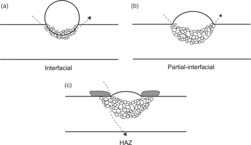
5.16 Schematic of failure modes with increasing weld current; interfacial (a), partial-interfacial (b) and HAZ (c). Source: With kind permission from Springer Science + Business Media: Metallurgical Materials Transactions A, Resistance microwelding of Ti-55.8 wt pct Ni Nitinol wires and the effects of pseudoelasticity, 43(8), 2012, p. 2969, Tam, B., Pequegnat, A., Khan, M.I., Zhou, Y., Figure 9.14
Effects of micro-resistance spot welding (MRSW) on NiTi microstructure and phase transformation
Nitinol alloys exhibiting pseudoelastic properties are thermomechanically manufactured to have a fine-grained base metal. However, heat generated at the weld interface during the initial application of current results in recrystallization and the onset of microstrcutral changes, as shown in Fig. 5.17a (HAZ outlined using dashed lines). At low currents, insufficient bonding (Fig. 5.17b) occurs due to the entrapment of surface oxides and contaminant.14 Both base and weld metals of Nitinol often contains finely dispersed precipitates in the microstructure, which is often TiC compounds formed during the production of ingots.
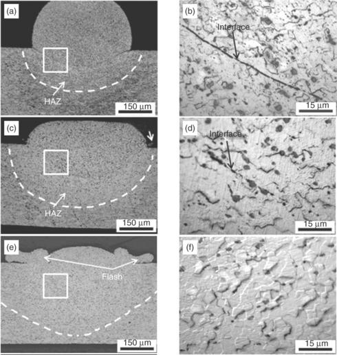
5.17 Cross-sections of joints welded at different welding currents; 145 A (a, b), 195 A (c, d) and 245 A (e, f). Heat-affected zone (HAZ) located between bond interface and dashed lines. Source: With kind permission from Springer Science + Business Media: Metallurgical Materials Transactions A, Resistance microwelding of Ti-55.8 wt pct Ni Nitinol wires and the effects of pseudoelasticity, 43(8), 2012, p. 2969, Tam, B., Pequegnat, A., Khan, M.I., Zhou, Y., Figure 3.14
As weld currents increase the HAZ widens (Fig. 5.17c). Weld microstructure undergoes grain growth at the faying surface, resulting in the partial disappearance of the bond interface (Fig. 5.17d). Squeezed out metal and surface contaminants, commonly referred to as ‘flash material’, is pushed to the joint periphery. This is facilitated by the combination of initial high resistance heating at the faying surface and electrode force, which melts the surface material and pushes molten surface material towards the joint periphery.14 Weld microstructure at currents up to 245 A experience further widening of the HAZ and complete elimination of the bond interface while more flash material gets expelled (Fig. 5.17e and 5.17f).
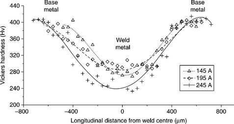
Recrystallization and grain growth results in a drop of hardness values (softening) near the weld zones. The effects of current on weld hardness are shown in Fig. 5.18.14 Softening become more pronounced at the interface as higher currents are applied and more heat is generated.
5.18 Hardness traces along cross-section of welds made using currents of 145 A, 195 A and 245 A. Source: With kind permission from Springer Science + Business Media: Metallurgical Materials Transactions A, Resistance microwelding of Ti-55.8 wt pct Ni Nitinol wires and the effects of pseudoelasticity, 43(8), 2012, p. 2969, Tam, B., Pequegnat, A., Khan, M.I., Zhou, Y., Figure 5.14
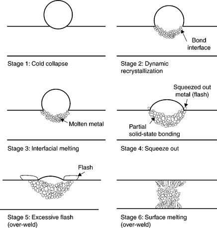
The primary joining mechanism for MRSW of crossed Nitinol wires is solid state, similar to Ni and 304 SS crossed-wires.20,21 The MRSW of Nitinol process can be summarized in six main stages, shown schematically in Fig. 5.19.14 The initial stage 1 ‘cold collapse’ describes the mechanical deformation imposed by the electrode force, from which a larger contact area was formed. Subsequent application of welding current increases temperature at the interface, resulting in ‘dynamic recrystallization’ (stage 2) of the fine-grained base-metal microstructure and softening in the HAZ. As peak temperatures surpass the solidus temperature at the interface, ‘interfacial melting’ (stage 3) occurs, followed by stage 4 ‘squeeze out’ where the electrode force pushes the partially molten metal towards the weld perimeter. This stage is necessary for good solid-state bonding as contaminants are removed from the junction, improving surface conditions for crystal-lographic matching and interdiffusion of atoms across the interface.14 The large amount of expulsion with increasing welding currents is referred to as stage 5 ‘excessive flash’, which introduces undesired defects in the weld metal. Further increase in currents induces melting of the wire surfaces (stage 6 ‘surface melting’) and sticking of welds to the electrodes, which can significantly affect weld quality and shorten electrode life.19
The intrinsic phase transformation behaviour of Nitinol is strongly influenced by thermomechanical processing. DSC curves for as-received, heat-treated base materials and welds produced at select weld currents are shown in Fig. 5.20.14 Like LMW, RMW weld metal experiences different transformations. Residual base-metal accounts for the high-temperature peaks, which has similar transformation temperatures to the base material. On the other hand, weld-metal transformation occurs at lower temperatures, much like laser welds that have not experienced significant Ni vaporization. Increasing welding currents has little effect on the weld transformation temperatures.
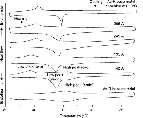
5.20 DSC heating and cooling curves of annealed wire, as-received wire (As-R) and weld made using various currents. Source: With kind permission from Springer Science + Business Media: Metallurgical Materials Transactions A, Resistance microwelding of Ti-55.8 wt pct Ni Nitinol wires and the effects of pseudoelasticity, 43(8), 2012, p. 2969, Tam, B., Pequegnat, A., Khan, M.I., Zhou, Y., Figure 10.14
Nitinol is known to exhibit broad temperature peaks when mechanically strained and narrow when fully annealed to its intrinsic state15–18 as observed in Fig. 5.20. Cold working results in higher transformation temperatures, since higher activation energy is required to overcome the internal stress induced by random dislocations.15,17,18 Annealing previously thermomechanically processes base-metal reduces transformation temperatures. Similarly, during welding the high-temperature workpieces experience resetting of the effects of previous thermomechanical processing and return the material to near fully annealed state. A higher degree of base-metal annealing occurs at a higher welding current, which results in a more defined temperature peaks.
5.4 Future trends
Shape-memory alloys are complex materials which require a thorough understanding prior to being properly implemented in medical devices. Thus far, these alloys have been successfully applied in numerous medical devices and have been increasingly sought after due to their excellent biocompatibility and unique functional properties. As the fundamental material knowledge base continues to spread, so will application in medical (and non-medical) devices. Welding has been a key restriction when implementing SMAs and, as joint complexity increases, these challenges will need to be resolved. Hence advances in SMA-welding techniques, such as refining process parameters and developing new filler materials, will continue for application-specific needs.
5.5 Conclusion
This chapter has shown that welding significantly impacts on the phase transformation behaviour of Nitinol. Specifically, two welding processes have been examined, including LMW and RMW. Local vaporization experienced during laser welding alters the local microstructure from austenite to martensite phase, reducing the mechanical strength. In contrast, resistance heating from the resistance-welding process anneals the original base metal, producing a HAZ that mimics solid-state solution treatment. These local modifications in the weld zones can adversely affect the functional properties of Nitinol and need to be considered in applications where RMW is implemented.
5.6 References
1. Lin, H.C., Wu, S.K. Tensile behavior of a cold-rolled and reverse-transformed equiatomic TiNi alloy. Acta Metallurgica et Materialia. 1994; 42(5):1623.
2. Shabalovskaya, S.A. Proc. ICOMAT 95. J. Phys. IV.. 1995; C8:1199.
3. Shüßler, A. Micro-machining and joining of NiTi-alloys using Nd:YAG lasers: status and prospects. Proceedings of the second international conference on Shape Memory and Superelastic Technologies (SMST-97), Pacific Grove, CA, 1997.
4. Yan, X.J., Yang, D.Z., Qi, M. Rotating–bending fatigue of a laser-welded superelastic NiTi alloy wire. Mater. Charact.. 2006; 57:58.
5. Buehler, W.J., Gilfrich, J.W., Wiley, R.C. Effect of low-temperature phase changes on the mechanical properties of alloys near composition NiTi. J. Appl. Phys.. 1963; 34:1475.
6. Chang, L.C., Read, T.A. Plastic deformation and diffusion-less phase changes in metals – the gold-cadmium beta phase. Trans. AIME. 1951; 189:47.
7. Basinski, Z.S., Christian, J.W. Crystallography of deformation by twin boundary movements in indium-thallium alloys. Acta. Metall. 1954; 2:101.
8. Massalski T.B., Okamoto H., Subramanian P.R., Kacprzak L., eds. Binary Alloy Phase Diagrams. 2nd. ASM International, Materials Park, OH, 1990.:2874. [vol. 3].
9. Otsuka, K., Ren, X. Physical metallurgy of Ti–Ni-based shape memory alloys. Prog. Mater. Sci. 2005; 50(5):511.
10. Van Humbeeck, J. Shape memory alloys: a material and a technology. Adv. Eng. Mater. 2001; 3(11):837.
11. Khan, M.I., Zhou, Y.Microjoining in Medical Components and Devices. Materials Park, Ohio, USA: ASM International, 2012. [ASM Handbook, Volume 23, Materials for Medical Devices].
12. Khan, M.I., Panda, S.K., Zhou, Y. Effects of welding parameters on the mechanical performance of laser welded Nitinol. Mater. Trans. 2008; 49(11):2702.
13. Hsu, Y.T., Wang, Y.R., Wu, S.K., Chen, C. Effects of CO2 welding on the shape memory and corrosion characteristics of TiNI alloys. Metal. Mater. Trans. A. 2001; 32A(3):569.
14. Tam, B., Pequegnat, A., Khan, M.I., Zhou, Y. Resistance microwelding of Ti-55.8 wt pct Ni Nitinol wires and the effects of pseudoelasticity. Metal. Mater. Trans. 2012; 43(8):2969.
15. Kuita, K., Matsumoto, H., Abe, H. Transformation behavior in rolled Nitinol. J. Alloys Comp.. 2004; 381:158.
16. Frick, C.P., Ortega, A.M., Tyber, J., Maksound, A.El.M., Maier, H.J., Liu, Y., Gall, K. Thermal processing of polycrystalline Nitinol shape memory alloys. Mater. Sci. Eng. A.. 2005; 405:34.
17. Miller, D.A., Lagoudas, D.C. Influence of cold work and heat treatment on the shape memory effect and plastic strain development of NiTi. Mater. Sci. Eng. A. 2001; 308:161.
18. Matsumoto, H. Transformation behaviour of NiTi in relation to thermal cycling and deformation. Physica B. 1993; 190:115.
19. Thornton, P.H., Krause, A.R., Davies, R.G. Contact resistances in spot welding. Weld. Res. Suppl. 1996; 75(12):402.
20. Fukumoto, S., Tsubakino, H., Zhou, Y. Heat input and deformation control in resistance microwelding of fine nickel wires. Weld. Int. 2006; 20(9):692.
21. Fukumoto, S., Matsuo, T., Tsubakino, H., Yamamoto, A. Resistance microwelding of SUS304 stainless steel fine wires. Mater. Trans. 2007; 48(4):813.