Advanced metal–ceramic joining techniques for orthopaedic applications
Abstract:
The types of metals and ceramics to be joined, their application, features and characteristics are preliminarily summarized. The main challenges are pointed out and discussed, possible solutions envisaged. As a consequence, general methods for joining metals to ceramics are presented. Their strong and weak points and possible outcomes are presented. The so-called direct bonding methods are discussed, in particular solid-phase, non-fusion welding. Strengths and weaknesses of techniques and materials are considered, as well as further concerns such as biocompatibility, thermal/chemical performances and long-term degradation. Indirect bonding methods are described, such as liquid-phase and solid-phase bonding, as well as active brazing techniques. Joining procedures, brazing agents, possible features and drawbacks, experimental testing issues and feasible applications are considered. Finally, expected future developments and their likely applications are presented together with sources of further information.
15.1 Introduction
Orthopaedic biomaterials dominate the market of biomaterials, thanks to their capability of restoring mobility and quality of life through fixation devices and joint replacements. The best-performing load-bearing joint-replacement prostheses should have a hybrid structure, made of metallic components, where strength, stiffness, fracture toughness and fatigue endurance are required, and ceramic components, where corrosion resistance, bio compatibility, friction coefficient and wear rate are of primary concern. This is why it is more and more desirable to combine the properties of ceramics and metals in medical devices (implantable prostheses or instrumentary tools). The challenge is to join metallic and ceramic components in such a way as to make the assembly able to sustain life-long cyclic loading, reliably and safely, even if their different chemistry, structures and properties can make their joining difficult or impossible (Pask, 1987). By the way, ceramic-to-metal joining represents a major issue in case of implantable neuromodulation medical devices as well, which require a hermetic sealing between ceramic housing and metallic flanges. As a matter of fact, neuromodulation is currently a hot research area in the implantable medical device industry (Koch, 2007; Daulton, 2010; Fowler et al., 2010; Haller et al., 2010; He and Colvin, 2010; Tziviskos, 2010; Blischak, 2011; Chiao and Chiao, 2011).
Theoretically, the components of hybrid metal–ceramic medical devices can be joined by means of three techniques: mechanical joining through integral attachment features (e.g. Morse taper); direct joining by means of solid- or liquid-phase bonding; indirect bonding by means of brazing or soldering agents (Carim et al., 1993). For realizing a reliable direct/indirect joint, an intimate contact between the adherents is needed, to be converted into an atomically bonded interface; besides, this interface must be able to accommodate residual stresses due to CTEs mismatch and generated by temperature variations during service (Loehman and Tomsia, 1988).
An innovative technique called active brazing, which uses special braze agents containing active metals (e.g. Ti or Zr) able to react with ceramics, can presently be considered the most promising process for joining metallic and ceramic parts of medical devices. Although brittle microstructures containing intermetallic compounds may be created at the interface, limiting its capability to accommodate CTEs mismatch, the prostheses assembled by active brazing have demonstrated being able to withstand not only large forces occurring during machining and polishing, but also simulated long-lasting physiological loads.
Besides active brazing technique, some other innovative processes are likely to be successfully adopted to join metals and bio-ceramics, in the field of both solid- and liquid-phase bonding. Solid-phase welds already demonstrated to be suited for joining metals and ceramic through different friction-welding processes, like ultrasonic welding and ultrasonic brazing. Very much promising are the ‘functional graded material (FGM) joints, which are able to join even strongly misfitting adherents through several interlayers of gradually varying metal–ceramic compositions. Combustion synthesis (CS) and self-propagating high-temperature synthesis (SHS) represent the more efficient techniques to produce graded layers.
Although ceramics melt at a very high temperature, inducing phase transformation and cracking inside the heat-affected zone, liquid-phase techniques, especially those based on a high-energy density process, like EBW and LBW, are becoming more and more popular, thanks to their capability to produce deep weld beads and narrow heat-affected zones. Electron beam brazing and laser brazing may be used as well: here electrons or photons beams locally heat a joint, where the filler metal is pre-placed in some form. The main advantages of these processes consist in very rapid heating, very small thermally affected zone and accurate dimensional control.
15.2 The challenges of joining metals to ceramics
The worldwide market of biomaterials is dominated by orthopaedic biomaterials, which are enormously successful in restoring mobility and quality of life to millions of individuals each year, thanks to reconstructive implants (joint replacements) and fracture management products (fixation devices). Orthopedic biomaterials should be chosen among those materials which are able to withstand, over the years, high fatigue loading, being in the meantime bio compatible, corrosion-resistant and mechanically efficient (Pope and Fleming, 1991). Notwithstanding hundreds of different orthopaedic applications exist in the field of fixation and total joint arthroplasty (TJA), only a few orthopaedic polymers, metals and ceramics dominate, listed in Table 15.1 together with their primary uses (Hallab et al., 2004).
Table 15.1
Most common orthopaedic biomaterials with their primary uses
| Material | Primary use(s) |
| Titanium alloy (Ti6Al4V) | Plates, screws, TJA components (non-bearing surfaces) |
| Co–Cr–Mo alloy | TJA components |
| Stainless steel | TJA components, screws, plates, cabling |
| Poly-methyl-methacrylate (PMMA) | Bone cement |
| Ultra-high-molecular-weight-poly-ethylene (UHMWPE) | Low-friction inserts for bearing surfaces in TJA |
| Alumina (Al2O3) | Bearing-surfaces TJA components |
| Zirconia (ZrO2) | Bearing-surfaces TJA components |
Adapted from Hallab et al., 2004, p. 528.
The principal function of long bones is to bear loads; therefore the most suited materials to replace their joints (hip, knee, shoulder and elbow) are metals. They provide appropriate characteristics in terms of strength, stiffness, toughness, hardness, durability, corrosion endurance and bio compatibility, even if their strength and stiffness considerably exceed those of bone, often leading to stress-shielding effects. The mechanical properties of main bio-metals are reported in Table 15.2, compared with bio-polymers and bio-ceramics. Among the three most popular families of orthopaedic metal alloys (titanium-based, cobalt-based, stainless steel), many different types are available, each of them particularly suited for specific applications. However, their widespread adoption as load-bearing implant materials is mainly due to high corrosion resistance; on the other hand, they are generally affected by high density, elevated friction coefficient and low wear resistance (Barbosa, 1992). These drawbacks have given to ceramics the opportunity to become a viable solution for certain specific applications (Hench, 1991).
Table 15.2
Mechanical properties of the most popular orthopaedic biomaterials

*c, compression; t, tension.
†HVN, Vickers Hardness Number, kg/mm.
Adapted from Hallab et al., 2004, p. 535.
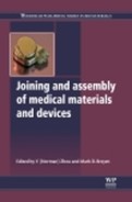
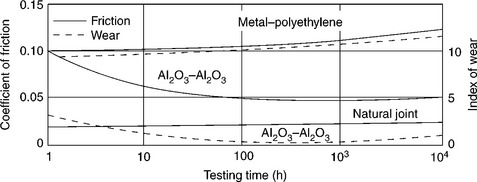
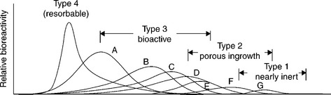
Among different kinds of ceramics, only dense, non-porous, nearly inactive ones are suited for bearing surfaces of TJA components, where their excellent biocompatibility, elevated compressive ultimate strength, low coefficient of friction and high wear resistance (Fig. 15.1) can be exploited thanks to their low rate of bio-reactivity (Fig. 15.2) and absence of formation of interfacial bone tissue (Fig. 15.3) (Hench and Best, 2004). Although adopted in Europe for over 40 years, it is only relatively recently that the FDA (3 Feb. 2003) has approved non-cemented ceramics cups press-fitted into the hip acetabulum. The mating femoral ball is made of ceramics as well, connected through a Morse taper to the metallic stem (Fig. 15.4). Prostheses for TJA of elbow, shoulder and knee, provided with ceramics parts (heads, condyles) have been implanted for many years as well and are likely to be FDA approved in the near future.
15.1 Friction and wear of Al2O3–Al2O3 hip joint compared to a metal–polyethylene prosthesis and a natural joint in in-vitro tests. Source: Reprinted from Hench and Best, 2004, p. 158.
15.2 Relative rates of bioreactivity for ceramic implants materials. A, 4555 Bioglass; B, KGS Ceravital; C, 55S4.3 Bioglass; D, A/W glass–ceramic; E, hydroxyapatite; F, KGX Ceravital; G, Al2O3, Si3N4. Source: Reprinted from Hench and Best, 2004, p. 154.

15.3 Time dependence of formation of bone bonding for the materials shown in Fig. 15.2. Source: Reprinted from Hench and Best, 2004, p. 154.
If their grains are very small (< 5 µm) and have a very narrow size distribution, the ceramics get excellent tribologic properties (friction and wear), since very low surface roughness values (Ra < 0.02 mm) are obtained. This leads to wear of ceramics-on-ceramics sliding surfaces being nearly ten times lower than corresponding metal-polymer coupling (Cooper et al., 1991). In general, long-term outcomes are excellent, although stress-shielding effects due to high elastic modulus of ceramics could result in bone atrophy and acetabular cup loosening, mainly in the case of old patients and osteoporotic bone. Concerns about alumina (Al2O3) brittleness and poor tensile strength are addressed by reducing grain size and porosity, increasing degree of purity and improving processing routes (i.e. adopting hot isostatic pressing, HIP). Zirconia (ZrO2) was introduced 25 years ago as an alternative to Al2O3 in consideration of its superior strength (100% higher) and modulus (80% lower) over competitors; such properties make ZrO2 possibly more resistant and mechanically compatible with surrounding bone material (Hench et al., 1991).
In synthesis: the best load-bearing joint-replacement prosthesis (hip, knee, shoulder, elbow) should have a hybrid structure, and be made of metallic components (stem) where strength, stiffness, fracture toughness and fatigue endurance are required, and ceramic components (ball-and-socket, condyles articulating surfaces) where corrosion resistance, bio compatibility, friction coefficient and wear rate have to be considered. These are the reasons why it is frequently desirable to combine the properties of ceramics and metals in medical devices (implantable prosthesis or instrumentary tool as well): joining these basically dissimilar materials has now become necessary, not simply interesting. The challenge is to join metallic and ceramic components in such a way to make the assembly able to sustain life-long cyclic loading, reliably and safely.
Compared to metals, ceramics are stronger (mainly in compression), more capable of retaining stiffness, strength, hardness and wear endurance at high temperature, more resistant to corrosion and oxidation (even at high temperature), less thermally and electrically conductive and less sensitive to thermal expansion/contraction. Some of these differences are shown in Table 15.3. Such different properties are due to basic differences in atomic microstructure. The micro-structure of ceramics is made of ionic, covalent or mixed ionic-covalent bonds, while the micro-structure of metals consists of typical metallic bonds, where a lattice of positive ions is permeated by a cloud of electrons, free of moving under the action of electric or thermal stimuli. Such different kinds of bonds lead to different values of melting point, strength and stiffness. In particular, all these are higher for ceramics than for metals, thanks to their ionic and covalent bonds, which are intrinsically stronger (Hench and Wilson, 1991).Another basic difference between ceramics and metals resides in brittleness of the former vs the ductility of the latter (due to the ability of metals to slip without disrupting atomic-level periodicity, thanks to the movement of dislocations). Furthermore, differences in electrical, thermal, optical and magnetic properties are owed to differences in electron distribution and spins. On the other hand, at micro-structural level, ceramics contain flaws, cracks and pores, which limit tensile strength and tension-tension or alternate fatigue endurance, because such load conditions open and extend flaws, unstably propagating cracks up to sudden, brittle failure (Hench and Wilson, 1993). Welding, brazing and soldering of ceramics give rise to larger and more complex dislocations that (with the exception of nano-structured ceramics) may prevent ductile deformations and induce low toughness and poor energy absorbing capability. For all that, each of the two materials is able to fulfil different requirements, even if their different chemistry, structures and properties can make their joining difficult or impossible (Messler, 2004).
Table 15.3
Properties of bioceramics and some metals for comparison
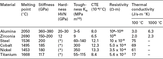
HVN, Vickers Hardness Number, kg/mm.
(*)Dependent on alloying.
Adapted from Messler, 2004, p. 586.
Theoretically, the components of hybrid metal–ceramic medical devices can be joined by means of one of these three techniques: (i) mechanical joining by interlocking, fastening or through integral design attachment features (e.g. Morse taper); (ii) direct joining by means of non-fusion (solid-phase) or fusion (liquid-phase) bonding; (iii) indirect bonding by means of polymeric adhesives, glasses, brazing or soldering agents. With the exception of mechanical joining, to realize a stable and reliable joint, different conditions should be met: (a) an intimate (atomic level) contact between the adherents has to be achieved; (b) the contacting surfaces should be converted into an atomically bonded interface; (c) the interface must be able to accommodate the residual stresses due to adherents CTE mismatch and generated during cooling down after fabrication or temperature variation during service (e.g. autoclave sterilization cycles) (Tomsia et al., 1991).
15.3 Mechanical joining techniques
Mechanical joining between metals and ceramics can be performed through several methods, like interlocking, press-fitting, clamping, fastening and integral threading. In case of fastening, possible damages due to inherent ceramics brittleness could arise. Such damages may derive from bearing and clamping loads and have to be limited by adopting large contact areas (bolt heads, nuts and washers), as well as compliant interlayers (metal liners, sleeves and inserts). Besides, holes for studs, pins and fasteners are difficult to be machined in ceramics, owing to cutting-tool wear and possible ceramics chipping and cracking; preferably, they should be integrally moulded and fired-in; in any case, generous fillets have to be provided. Moreover, since compressive stresses are better tolerated by ceramics than tensile ones, design should avoid complex states-of-stress (e.g. bending and deviated compression) leading to dangerous situations. Finally, large differences between CTEs of metals and ceramics should be accurately considered to reduce the effects of thermal loading due to autoclave sterilization process. Having this in mind, suitable types of ceramics and metals should be chosen for minimizing such a mismatch; deformable metallic fasteners should allow a certain degree of mutual displacement (slippage) between adherents; ductile intermediate components should be provided, able to plasticize and flow (Messler, 2004).
The main advantages of mechanical vs brazed joints are: good mechanical strength under moderate loads (even at high temperature), capability to accommodate strain mismatches due to thermo-elastic differences and, above all, possibility of intentional disassembling to repair, upgrade and modify instrumentary tools and ancillary equipments. Besides, such a characteristic lends modularity to families of implantable devices and allows to customize (in the surgical room) implantable systems made of different components. To integrally connect metallic and ceramic parts through mating geometric features, these should be built into the devices at the initial design stage, like in the case of Morse taper coupling between head and stem of hybrid metal–ceramic hip and shoulder prostheses.
In a Morse taper coupling, the conical female cavity (bore) is characterized by an angle slightly unlike the angle of the stem male cone (trunnion). So doing, if the two mating parts are coupled, they are not in contact on a surface but along a circumference; for this reason, when the trunnion compresses the wall of the bore and tends to expand it, the stresses that arise create a built-in constraint between the two parts. A modular system based on Morse taper coupling offers the capability to combine every trunnion supplied by a producer with every bore made by another producer, provided they have the same degree of tapering. On the other hand, remarkable concerns of fretting and wear afflict such kind of mechanical connection.
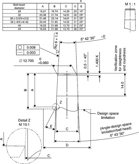
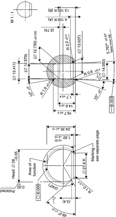
An international standard does not exists to define dimensions and tapering of male and female cones, but main producers of ceramic heads for hip prostheses have imposed their standard to which the dimensions of metallic stems cones have to comply (Figs 15.5 and 15.6). Besides, in order to allow complete inter-changeability between ceramic and metallic heads, the dimensions of metallic heads should conform to such standard as well. As a consequence, the so-called ‘Euro-cone 12–14’ has almost imposed itself among the totality of hip prostheses producers.
15.4 Direct and indirect bonded joining techniques
A direct joining process leads to the connection between two materials thanks to the formation of primary bondings similar to those found in the original adherents; intermediate materials are not required.
An indirect joining process uses an intermediate material, which allows to overcome the incompatibilities (chemical, physical, thermal) of the two adherents.
15.4.1 Direct bonding techniques
A process of direct joining leads to the indissoluble connection between two materials thanks to the formation of primary bondings equal or similar to those found in the adherent materials: no intermediate materials are required. Metals and ceramics may be directly joined preferably through solid-phase non-fusion processes (diffusion welding) or (seldom) fusion techniques. These latter techniques are rarely adopted since intermixing of ceramic and metal liquid phases can hardly occur at atomic level due to basic differences between materials. Viceversa, non-fusion techniques like diffusion bonding, friction welding, chemical vapour deposition (CVD) and physical vapour deposition (PVD) are widely used, even if CVD and PVD are often not considered true welding processes because materials are joined atom-by-atom and not in-bulk.
Solid-phase diffusion welding has become very popular and is widely used thanks to its capability to achieve an atomic-level interface contact. To this purpose, very smooth and perfectly fitting surfaces have to be matched, in order to guarantee an intimate contact between a very large number of microscopic asperities, through which diffusion occurs. At the beginning, plastic deformation of metallic adherent happens, followed by creep, grains growth and diffusion in both metal and ceramic (Fig. 15.7). Similar melting points of adherents is not needed and successful welding of noble (Pt, Au, Ag, Pd) and transition (Fe, Ni, Co) metals to oxide-bioceramics (Al2O3) are reported. Their resistance to chemical and electrochemical corrosion, long-term stability and good reliability during service are well documented in literature (Kamachimudali et al., 2003; Jiang et al., 2005; Xiaochun et al., 2008; Atabaki, 2010). Diffusion bonding usually takes several minutes or a few hours (Messler, 2004).
15.7 Schematic illustration of the stages of solid-phase bonding of metals to ceramic. Source: Reprinted from Messler, 2004, p. 709.
Solid-state bonding process depends on the combination of surface and bulk chemical reactions. In general the adherents should be heated up to temperatures close to metal melting point while pressed together at pressures of 1–10 MPa, respectively suited for noble and transition metals. Shear ultimate can reach 80–100 MPa. The strength of the joint is also strongly dependent on the coefficient of thermal expansion (CTE) of the metallic adherent, as shown in Fig. 15.8. Mechanical performances of the joint descend not only from the nature and the compatibility of the adherents, but also from the proper choice of technological parameters, like process temperature, pressure and duration, as well as surfaces roughness, cleanliness and possible pre-conditioning. Adherents contours should be free from contaminants, and a certain degree of metal roughness and ceramic smoothness are beneficial. It is convenient to increase process duration, bonding pressure and, above all, temperature, owing to the dependency of diffusion rate D on the absolute temperature T given by the Arrhenius relationship:
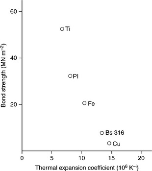
15.8 A plot of diffusion bond strength versus CTE for various metal–alumina combinations. Source: Reprinted from Messler, 1993, p. 516.
where Q is the activation energy needed to start diffusion and R is the gas constant. However, too long process duration or too high temperature levels can induce chemical reactions at the interface, leading to ceramic discolouration, degradation, mismatch strains and residual stresses due to the misfitting of specific volumes of reaction products. In general, vacuum or inert environment should be preferred, even if, in particular cases, an oxygen-rich atmosphere may improve the bonding between noble metals and oxide-bioceramics (Al2O3, ZrO2).
Diffusion in ceramics is more difficult to induce than in metals since diffusion of two or more elements should maintain charge neutrality in ionically bonded materials. This is difficult to obtain, since diffusion is a stochastic process and non-metallic species are usually much larger than metallic ones. Besides, diffusion is a process largely relying on temperature: since diffusion rates speed-up at values approaching 60–70% of metal melting temperatures and ceramics are inherently refractory (i.e. have very high melting points) materials, satisfactory diffusion rates inside ceramics can hardly be obtained in case of low-melting metallic adherents (Messler, 2004).
Other solid-state non-fusion techniques are: electrostatic bonding, where a voltage applied across the adherents improve ionic conduction and induce electrostatic attractive forces, friction welding and ultrasonic welding, although these two latter processes are made difficult by ceramics inherent low plasticity. In any case, once the bonding between a metal and a ceramic is obtained, its stability and reliability should be preserved during the entire service life of the assembly. The main issue concerns its ability to accommodate non-mechanical strains and residual stresses due to CTE mismatch. They arise at metal–ceramic interface during cooling down after joint fabrication or are due to temperature excursion during autoclave sterilization of the implantable prosthesis or instrumentary tool. To this regards, a proper design of the device is of crucial importance, even though diffusion-bonded joints can hardly accommodate such kind of mismatches, owing to the high values of pressure which have had to be applied to cause bonding.
15.4.2 Indirect bonding techniques
The most widely used method for obtaining strong and reliable joints between metals and ceramics consists in using intermediate materials, which allows the chemical, physical, thermal and mechanical incompatibilities of these classes of materials to be overcome. These materials may be polymeric adhesives, glasses, glass–ceramics, oxide-mixtures or (more often) metals or metallic alloys. The intermediates may be in solid- or liquid-state, but, in any case, give rise to the so-called indirect bonding techniques.
In general, solid-phase indirect bonding techniques performed through hot-pressed metallic interlayers are characterized by two advantages if compared with liquid-phase processes: (i) since bonding agent remains in the solid-state, no concerns about metal–ceramic wettability arises; (ii) intrinsic ductility of metallic interlayer is particularly efficient in accommodating CTE mismatches. This particularly holds when low-melting-point metals are adopted and low process temperatures can be kept; besides, the danger of thermal degradation is minimized. The best choice for solid-phase indirect bonding interlayers is aluminum (for joining Al2O3 to titanium alloys or stainless steel in instrumentary tools), to be replaced by silver when parts of implantable devices (which must comply with biocompatibility requirements) have to be joined.
In liquid-phase indirect bonding, glasses or (more often) molten metals fill the meatus between the faying surface of metal and ceramic (Fig. 15.9). The bonding occurs if both materials are satisfactorily wetted by filler and if adhesion resists to post-fabrication cooling down. Depending on the filler melting temperature, the process is called either brazing (Tm > 450 °C) or soldering (Tm < 450 °C). In general, glasses wet oxide-ceramics better than metals do, but these latter are more capable to accommodate the effects due to CTEs mismatch.

15.9 Schematic illustration of the stages of liquid-phase bonding of metals to ceramic. Source: Reprinted from Messler, 2004, p. 708.
Usually, ceramics poor wettability descends from their localized ionic or covalent bonding, which reduces very much electrons movement capability. This particularly holds for oxide-ceramics, while borides, nitrides and – mainly – carbides can often be wetted well.
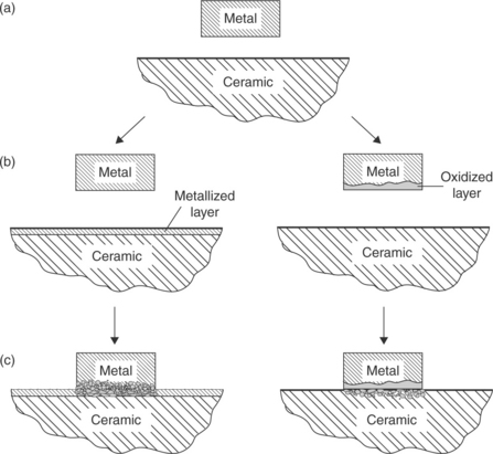
To promote wetting, inherently different materials should be made similar. The problem is to join two dissimilar un-compatible surfaces, one ceramic, the other metallic. To make them compatible, two approaches can be adopted: (a) to oxidize the metallic surface; in this way, the ceramic being an oxide as well, we can join an oxide to an oxide; and (b) to cover the ceramic surface with a metallic layer; in so doing, we can join a metal to a metal. Metallizing can be accomplished through sintered metal powder technique, titanium hydride powder activation or refractory-metal salt process. Other methods for ceramic metallization may consist in metal–glass surface powder sintering, CVD, PVD, sublimation (vacuum metallizing), sputtering, ion plating and plasma spraying.
Another approach, called active brazing, consists in using a filler (brazing agent) containing an active metal (e.g. Ti or Zr) which reacts with the ceramic (Nicholas, 1986). Although brittle micro-structures containing intermetallic compounds may be created at the interface, limiting its capability to accommodate CTEs mismatch, active brazing can presently be considered one of the most promising techniques for structurally joining metallic and ceramic parts of medical devices (Nicholas and Crispin, 1989).
15.5 Active brazing joining techniques
Molten metals do not directly wet ceramics owing to different atomic structures. The same happens in case of indirect joining using passive filler metals (brazes). Vice versa, active brazes, doped with reactive alloying elements, induce chemical interactions with ceramics and allow more stable joints.
15.5.1 Metallurgy of active brazing
Active brazing is particularly suited to produce ceramic–metal joints. Generally molten metals do not wet ceramic materials due to the fundamentally different atomic structures. In order to wet the ceramic material, active brazes are doped with extremely reactive alloying elements like Ti or Zr (Paiva and Barbosa, 1997). The metallurgical effect of those active filler metals is to induce a chemical interaction between the filler metal and the ceramic during the brazing process. Due to a mismatch in thermal expansion coefficients of ceramics and metals, residual stresses are induced into the ceramic that can cause its failure, provided the misfit is large enough and no stress relaxation measures are undertaken. Hence, the development of ductile filler metals, in order to limit thermally induced stresses in the ceramic, is crucial. Moreover, the ceramic–metal joint has to fulfil the mechanical requirements.
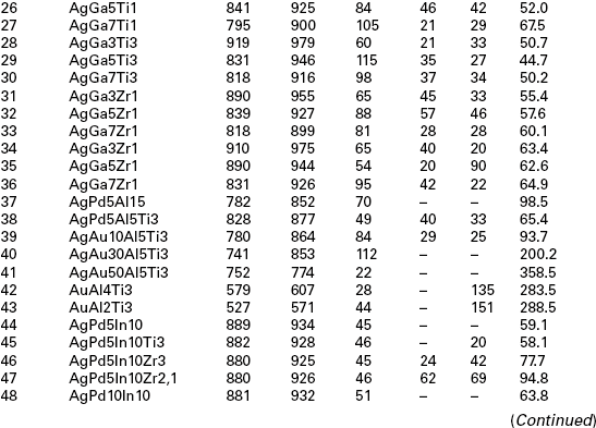
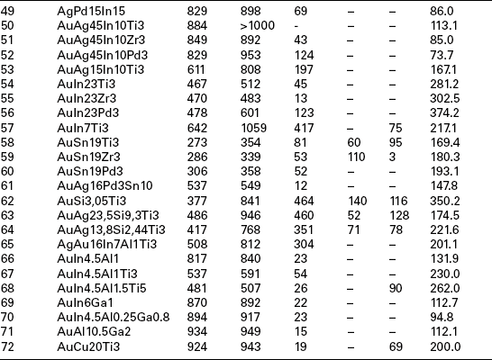
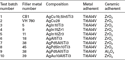
For biocompatibility reasons, the metallurgical realm for the filler metals has to be restricted to alloys predominantly based on precious metals like the elements Ag, Au and Pd. To join bio-ceramics and Ti6Al4V, which is the typical alloy for the production of orthopaedic endoprosthes, these alloys must be doped with either Ti or Zr. The maximum brazing temperature has to be limited to 950 °C due to possible micro-structural transformations of Ti6Al4V and with that also the liquidus temperature of the active braze is limited. The liquidus temperature of Ag (961 °C), Au (1064 °C) and Pd (1552 °C) is too high to fulfil such a requirement. Hence, non-reactive and non-toxic alloying elements, able to lower the liquidus temperature of the precious metals, are demanded. Phase diagram and biocompatibility literature show that promising elements are In, Al, Ga, Cu, Sn and Si, elements which allow reducing the liquidus temperatures for either Ag and Au. The liquidus temperature of Pd is too high to be employed as matrix metal. Therefore Pd has to be excluded as matrix metal and more Au- and Ag-based alloys should be examined. Table 15.4 lists 72 viable filler metals produced by arc-melting; chemical composition is reported, starting with the base metal and giving the percentage weight content of alloying elements; melting and wetting behaviour and hardness are indicated as well (Sicking, 2000). Noble metals Au, Ag and Pd are fully biocompatible, Al and Sn are surely non-biocompatible, while the bio compatibility of In and Ga is still questionable, even if considered satisfactory in most literature (Kimura, 1988; Iijima, 1989; Chandler et al. 1994; Wataha et al., 1994).
Table 15.4
Chemical composition, melting and wetting behaviour and hardness of 72 viable filler metals, fabricated by arc melting

Due to the overwhelming importance of the wetting behaviour, wetting tests should be performed for all filler metals containing active elements and typical bio-ceramics alumina (Al2O3) and zirconia (ZrO2) in a vacuum furnace (950 °C/10 min heating/cooling rate). Most of the Ag-based alloys show an acceptable (α < 90 °C) or good (α < 30 °C) wetting behaviour and thick reaction layer on both substrates. An increase in the Au content leads to an enhanced wetting angle and reduced reaction layer thickness. For this reason only four Au-containing alloys (numbers 39, 58, 59, 72) may be considered as promising. An interesting aspect is the change in colour of the zirconia substrate due to the chemical reaction in the interface. This change is a hint referring to the extent of the occurring interface reaction. The colour change is caused by an oxygen diffusion from the former stochiometric ZrO2 to the reaction layer which is formed at the ceramic–metal interface. A detailed evaluation and assessment of melting ranges (Tsol/Tliq), hardness and micro-structure shows the suitability of 38 filler metals among the original 72. The additional consideration of wetting behaviour and filler metal spreading on oxide ceramics substrates, as well as the discolouration of ZrO2 lead to the selection of 11 most promising active brazes (numbers 5, 9, 11, 18, 27, 38, 39, 45, 58, 59, 72).
Brazing experiments should be performed in a vacuum furnace with a vacuum quality of 5 × 10⁻⁵ to1 × 10−4 mbar to further investigate the suitability of such active brazes. The ceramic samples to be employed have a surface roughness of Ra < 0.4 µm since wetting experiments show that a higher surface quality does not induce a significant improvement in the wetting behaviour. A maximum brazing temperature of 950 °C and a dwell time of 10 min are employed to evaluate the suitability of the filler metals for joining Ti6Al4V to oxide ceramics. These parameters guarantee a sufficient energy input to trigger the chemical reaction at interface and to avoid harmful micro-structural transformations of Ti6Al4V. Brazing experiments point out how difficult is to actively braze Al2O3 and Ti6Al4V: as a matter of fact, with the exception of filler metal number 38, all joints crack due to CTEs mismatch. Viceversa, brazing experiments employing ZrO2 and Ti6Al4V show encouraging results. Metallographic evaluation and discolouration of ZrO2 lead to the selection of the best seven active brazes (numbers 5, 9, 11, 18, 38, 39, 45) among the original 11. Further analysis of interfacial reaction products allows to select three filler metals: numbers 38 and 39 may be selected due to their excellent mechanical behaviour, number 9 in consideration of preliminary biocompatibility tests. Table 15.5 summarizes the results of four-point-bending mechanical tests performed on samples actively brazed with these three filler metals and different brazing parameters. However, a set of optimized parameters has to be defined for filler metals according to two criteria: maximization of mechanical strength and minimization of energy input.
Table 15.5
Four-point-bending strength of coupons actively brazed with filler metals number 39, 38 and 9

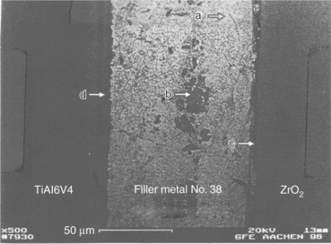
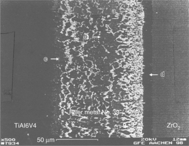
Figure 15.10 shows a SEM image of an actively brazed Ti6AlV4–ZrO2 joint employing the optimized set of parameters for braze number 39. The corresponding line-scan shows that the filler metals micro-structure is almost homogeneous and contains mainly silver with little aluminium in solid solution. The grid content is next to zero. Table 15.6 shows quantitative analysis of a representative peak within the filler metal (spot a in Fig. 15.10). The filler metal thickness is around 65 µm. The white-coloured hard phase is made of Au, Al, Ti and Zr. The reaction layer at the interface between filler metal and ZrO2 is hardly visible but is thinner than 1 µm (spot b in Fig. 15.10). A grey-coloured band of thickness 3–5 µm appears between filler metal and Ti6Al4V (spot c in Fig. 15.10). The line-scan shows an enrichment of Au, Al and Ti for this zone. A quantitative analysis of a representative peak gives the chemical composition reported in Table 15.7. Figure 15.11 shows a SEM image of Ti6Al4V–ZrO2 joint brazed with the optimized set of parameters for braze number 38. Figure 15.12 shows a typical SEM image of Ti6Al4V–ZrO2 joint brazed with filler metal number 9. A quantitative SEM analysis shows that the higher thickness of the reaction layer and the Ti-containing hard phase at mid-seam lead to lower mechanical performances. When filler metal number 9 is adopted, Ti coming from Ti6Al4V has no barrier which avoids erosion into the seam: as a consequence the lowest strength is achieved.
Table 15.6
Quantitative SEM analysis of filler metal number 39 (spot a in Fig. 15.10)
| Element | Weight % | Atomic % |
| Silver (Ag) | 94.97 | 86.94 |
| Gold (Au) | 1.61 | 0.81 |
| Aluminum (Al) | 3.25 | 11.90 |
| Titanium (Ti) | 0.17 | 0.35 |
Table 15.7
Quantitative SEM analysis at Ti6Al4V – filler-metal interface (spot c in Fig. 15.10)
| Element | Weight % | Atomic % |
| Silver (Ag) | 1.89 | 1.10 |
| Gold (Au) | 44.47 | 14.18 |
| Aluminum (Al) | 14.16 | 32.96 |
| Titanium (Ti) | 39.48 | 51.76 |
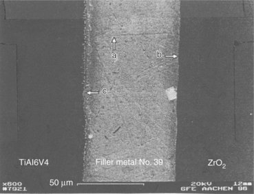
15.10 SEM image of an actively brazed Ti6Al4V–ZrO2 joint with filler metal number 39. (a) Filler, (b) filler-ceramic interface and (c) metal-filler interface.
15.11 SEM image of an actively brazed Ti6Al4V–ZrO2 joint with filler metal number 38. (a) Filler, (b) inclusion, (c) filler-ceramic interface and (d) metal–filler interface.
15.12 SEM image of an actively brazed Ti6Al4V–ZrO2 joint with filler metal number 9. (a) Filler, (b) inclusion, (c) metal–filler interface and (d) filler-ceramic interface.
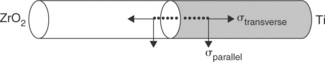
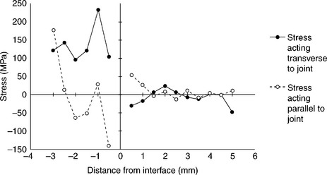
Joining of metals to ceramics leads to development of residual stresses due to the CTEs mismatch between the two materials. The magnitude and the nature (compressive or tensile) of such stresses depend on the extent of such mismatch, the component dimensions and the brazing temperatures. These stresses are usually the highest in magnitude at and near the joint region. High tensile stresses reduce the strength of joints and lead to cracking. A knowledge of such stresses, along with the results of mechanical tests are necessary to optimize the choice of brazing alloy and brazing parameters. To measure residual stresses, cylindrical metal/ceramic coupons 50 + 50 mm long, 10 mm in diameter may be used, whose geometrical details are summarized in Fig. 15.13. The measurement must be carried out across the joint interface at different locations and intervals of 0.5 mm along two directions viz. transverse and parallel to the joints. An X-rays stress analyser should be used to perform the measurement. Reflection may conveniently be analysed along 222 crystallographic plane with filtered Cr radiation (Ti6Al4V) and 133 crystallographic plane with filtered Co radiation (ZrO2).The irradiated area should be small enough (typically 0.5 mm × 4 mm). The beam-length direction must always be parallel to the joint interface in order to have a linear distance resolution of 0.5 mm. The measurements is usually performed according to the sin2Ψ method. For each stress computation, strain acting along eight different Ψ-directions are measured from X-ray diffraction line-shift analyses. It is convenient to use a least-square linear fitting procedure for computing stresses (elastic moduli taken from literature may be used to obtain stresses from measured strain data). A typical result is shown in Fig. 15.14. The measures at ZrO2 side of the joints show negligible scatter: stresses are mostly compressive and low in magnitude, except at regions very close to the joint interface where increase significantly. At Ti6Al4V side of the joints, tensile stresses are present at most locations. Close to the interface, most cases indicate low tensile or compressive stresses. This has to be expected, since CTEs mismatch is mostly felt in these areas. In case of Ti6Al4V–Al2O3 joints, measurements at Al2O3 side point out steep compressive stresses up to 1.5 mm from the interface, in both longitudinal and transverse directions.
15.5.2 Mechanical characterization
The mechanical characterization of actively brazed joints is generally performed through four-point-bending tests, using cylindrical specimens 10 mm in diameter, with 40 mm outer span and 20 mm inner span. The specimens are made of two halves, one metallic (Ti6Al4V) and one ceramic (Al2O3 or ZrO2) brazed together. Since ceramic represents the critical part of the specimen, testing should be carried out in compliance with standards for bending tests of technical ceramics (e.g. AFNOR B41–104). Testing has to be performed in servo-hydraulic testing machines under position control and slow cross head displacement rate (0.1–0.5 mm min−1). Fatigue tests should be performed in servo-hydraulic machines as well, using the same loading set-up and frequencies not higher than 10 Hz in tension-tension (R = 0.1). Figure 15.15 presents the results of static tests performed on specimens brazed with the filler metals summarized in Table 15.8. These tests show poor mechanical performances of most Ti6Al4V–Al2O3 specimens, to the exception of those brazed with filler metals 9, 38, 39. Testing on Ti6Al4V–ZrO2 specimens should be performed with both ‘white’ and ‘black’ zirconia. The dark layer appearing in white zirconia near the brazed interface, due to diffusion phenomema, is detrimental because of aesthetic reasons, but does not affect mechanical performances.
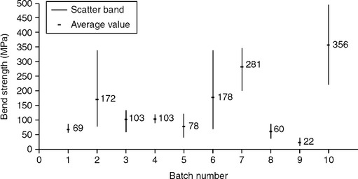
15.15 Four-point-bending static strength of brazed specimens (see Table 15.8).
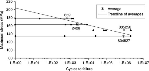
Fatigue tests should be performed under the same four-point-bending condition, at a maximum stress level slightly lower than the ultimate static bending strength and run-out at 2 × 10⁶ cycles. Tests results are summarized in Fig. 15.16. Notwithstanding high scatter in results, mainly affecting the first-quarter cycle (loading to start point), a qualitative trend-line can be established. SEM fracture surface analysis does not reveal any crack propagation. In most cases, fractures close to the point of maximum stress suggest mixed-mode failures, with cracks running from the ceramic-filler-metal interface to the metal-filler-metal one.
15.5.3 In-vitro testing
To in-vitro evaluate biocompatibility characteristics of metal–ceramic brazed joints and to assess the most suited filler metals, three crucial aspects should be analysed: (i) cell growth in presence of the material to be tested; (ii) cell adhesion and spreading; (iii) cell differentiation analysis. Human osteoblasts are employed as in-vitro cells assay. Osteoblasts are seeded in triplicate onto the Ti6Al4V-Al2O3 brazed samples and onto the negative control (polystirene dishes), using multiwell plates, at a density of 4000 cells/mL, in DMEM – 10% FCS. The incubation times are 24 h, 4, 7, 14, 21, 28 days. At the end of each incubation period, cells are detached from the substrate by tripsinization and incubation in trypan blue. The number of living cells is measured by using both haemocytometer and MTT colorimetric assay. The number of floating cells, the number of cells adhering to substrate and the ratio adhering/floating cells are assessed in each brazed sample. As far as cell differentiation analysis is concerned, osteoblasts cultures are stained with a modified von Kossa procedure for detection of Ca++ deposition. The presence of alkaline phosphatase (ALP) activity is determined through the Gomori’s method. The production of alkaline phosphatase is measured in cell lysates obtained after sonication of the cell pellet, by means of spectro-photometric analysis. Immuno-histochemistry uses the following antibodies: anti-type I, type II and type III collagen, anti-osteonectin, anti-vimentin and anti–fibronectin. Each slide is observed by light-microscopy and analysed by an image-analysis system. Samples for cell-adhesion analysis are prepared and observed using SEM.
Osteoblast count shows that filler metals numbers 5, 9 and 11 do not significantly inhibit osteoblasts proliferation as compared with control cultures. Cell survival is about 50% for filler metals numbers 39, 45 and 38, while commercial brazes CB1 – AgCu19,5In5Ti3 and VH 780 – AgCu28 show a high degree of citotoxicity. The number of floating cells is high for filler metals numbers 5, 9 and 11, owing to the persistence of a de-differentiated condition of the cultured cells. The number of adhering cells, which is related to the differentiation process of cultured cells, is high for filler metals numbers 39, 9, 11 and 45, while cell attachment is not detectable for filler metal number 18, CB1 and VH 780. If one consider the ratio between adhering and floating osteoblasts, or the ratio between the adhering and the total cell count, filler metals numbers 39 and 45 exhibit the highest values, followed by numbers 9, 38 and 11. As far as cell differentiation is concerned, filler metals numbers 11, 45 and 9 show the highest values of ALP production in the culture medium all along the culture period, followed by numbers 18 and 39. Moreover, if the ratio between ALP production and total number of cultured cells or the number of adhering cells is considered, filler metals numbers 45, 11, 18, 39 and 9 perform better. Such results suggest that only filler metals numbers 45, 11, 18, 39 and 9 are able to induce osteoblasts differentiation, while all the other ones seem to inhibit this process, as confirmed by histochemical analysis. Calcium deposition, as revealed by the von Kossa staining method, is found on filler metals numbers 39, 45 and 11. Immuno-histochemistry with anti-type I collagen antibodies is highly positive in samples numbers 39, 45 and 9. Anti-type III collagen immune reaction show to be positive in filler metals numbers 39, 45 and 9. Anti-osteocalcin is positive in filler metals numbers 39, 11 and 9. Finally, anti-vimentin is positive in filler metals numbers 45, 39, 11 and 9. As far as the morphology of adhering osteoblasts is concerned, cells show to be polygonal or elongated in shape, with the maximum diameters ranging between 15 and 20 µm, bearing villi, phyllopodia and lamellopodia. For CB1 filler metal, the number of adhering osteoblasts is low, above all on the brazed surface. They are flattened- and spindle-shaped, indicating the condition of metabolic resting. Osteoblasts adhesion in VH 780 filler metal is mild on the brazed surface as well. Most of them are flattened, but some are swollen and metabolic active.
The number of adhering cells per unit area is high in number 5 filler metal, but flattened, polygonal and not showing typical features of cells differentiation. Osteoblasts are less numerous in numbers 9, 11 filler metals, where the brazed surface shows both spindle-shaped and swollen cells, while osteoblasts are much more numerous on the metallic (Ti6Al4V) surface. On the contrary, filler metal number 18 shows a higher number of adhering cells on the ZrO2 surface, but are located far from the brazed surface. Subtile osteoblast cytoplasmic elongations bridging the two opposite surfaces can be found in filler metal number 38, where the number of cells per unit area is high on the brazed surface as well. Filler metal number 45 shows a high percentage of adhering osteoblasts. Cells are well differentiated and metabolically active. Filler metal number 39 shows the most effective features: osteoblasts number per unit area is about 4–5 times higher than for other filler metals. Cells are firmly attached to both ZrO2/Ti6Al4V surfaces and to the brazed area. They are swollen, exhibiting a ruffled surface and are actively sintetizing collagen and bone matrix (see Fig. 15.17). To quantitatively assess the in-vitro biological response of each filler metal, a scoring scale can be used. A score ranging from 1 to 9 is assigned to each filler metal per each test (cell growth, cell adhesion, ALP production, cell differentiation and cell adhesion on the brazed surface), depending on their better or worse behaviour. The results are reported in Table 15.9: filler metal number 39 gets the highest score, followed by samples numbers 45, 9, 11 and 5. The analysis of the results allows one to divide filler metals into four groups:
Table 15.9
Ranking of filler metals according to cell growth, cell adhesion, ALP production, cell differentiation and cell adhesion on brazed surface
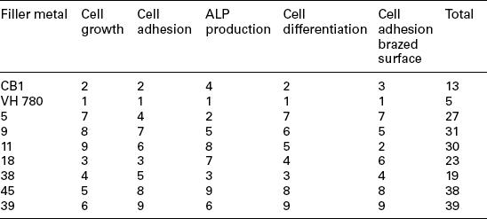
1. Filler metals numbers 9 and 11 promote osteoblasts growth and stimulate bony phenotype expression, but inhibit cells adhesion;
2. Filler metals CB1 and VH 780 inhibit cell growth, attachment and osteoblast differentiation;
3. Filler metals numbers 18 and 38 show a slight growth curve, very bad adhesiveness and do not inhibit differentiation;
4. Filler metals numbers 39 and 45 enhance cell proliferation, attachment and differentiation.
15.5.4 Industrial processing
Typical active brazing conditions for joining Al2O3 or ZrO2 ceramics to Ti6Al4V alloy are given in Table 15.10.
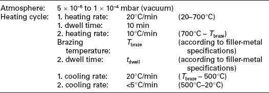
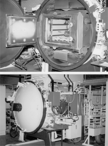
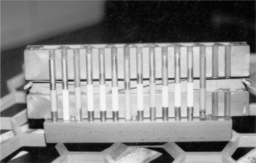
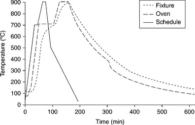
The type of brazing furnace should be chosen once components dimensions and optimum brazing conditions are identified. Different kinds exist, equipped with graphite or molybdenum heating elements; the main choice criteria should take into account: (a) maximum temperature capability (compliant with brazing temperature); (b) temperature uniformity; (c) chamber dimensions (compliant with the dimensions of the parts to be brazed and brazing fixtures); (d) cooling rate capability (< 5 °C/min); (e) degree of vacuum (< 2 × 10⁻⁶ mbar). Figures 15.18 and 15.19, respectively, show furnace and metal/ceramic cylindrical coupons aligned within the fixture, with numbers 9, 38 and 39 braze foils placed at samples interface contacts. Titanium parts should be placed upon ceramic parts to guarantee uniform self-weight loading during brazing. The fixture keeps the samples inclined at 10 ° from the vertical and is provided with a front cover to enable uniform heating/cooling conditions. Figure 15.20 reports the theoretical brazing cycle for filler metal number 39, along with actual temperature profiles measured by means of thermo-couples inside furnace and fixture.
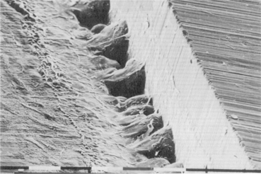
Once brazing process is completed, SEM analysis should be performed, considering both as-brazed surfaces and cross-sections made through the joints. Figures 15.21 and 15.22, respectively, show the typical micro-structure of numbers 38 and 39 alloys brazed joints. Figure 15.23 reports the compositional (energy dispersive X-ray spectroscopy – EDX) dot mapping for Ag, Al, Ti, Au and Zr (from top left to bottom right, respectively), showing the elemental partitioning between different micro-structural features. Selected area EDX analyses may be carried out at different locations and interesting micro-structural features, to semi-quantitatively determine their compositions. The energy dispersion spectra obtained from number 39 brazed joints are shown in Fig. 15.24. From the strength, micro-structure and joint integrity points of view, filler metal number 39 can be considered the best choice for industrial production of brazed-metal/ceramic orthopaedic prostheses. However, the wettability on ceramic could be improved through pre-metallization for obtaining more uniform braze interface.
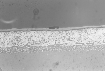
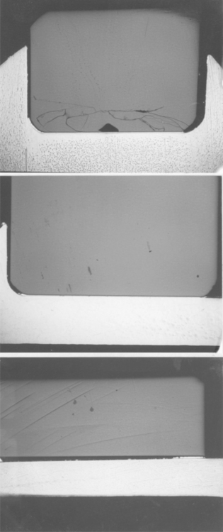
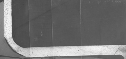
15.21 Centre of the joint brazed with filler metal number 38. Wide zirconia discolouration, reaction between brazing agent and titanium alloy and voids should be noted. Magnification × 2000.
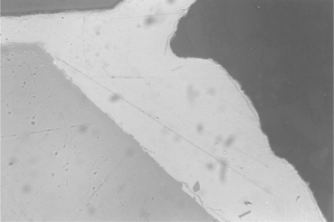
15.22 Edge of the joint brazed with filler metal number 39. Absence of zirconia discolouration and limited reaction between brazing agent and titanium alloy should be noted. Magnification × 2000.
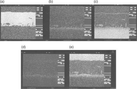
15.23 Compositional EDX dot mapping of the joint brazed with filler metal number 39. (a) Ag, (b) Al, (c) Ti, (d) Au, (e) Zr.
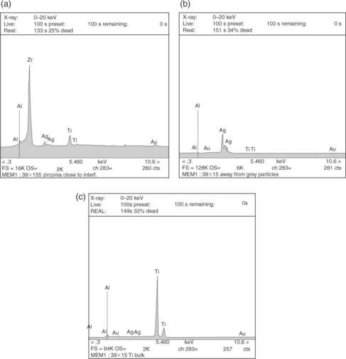
15.24 Energy dispersion spectra at various locations of the joint brazed with filler metal number 39: (a) 3 µm from interface, inside ZrO2; (b) inside homogeneous brazed area; (c) 150 µm from interface, inside T16Al4V.
The nominal chemical composition of the filler metal is decisive to get optimal brazing results. However, it has to be remembered that the production route (laboratory scale vs industrial scale) may influence the properties of the final active braze foils. Quantitative EDX analysis on a fixed area should be used to determine the chemical composition of un-brazed foils, even if, owing to the hard-phase formation and different homogeneity of braze foils, an exact quantitative comparison is seldom possible. Moreover, the EDX analysis is not suitable to analyse the accurate titanium content. Besides measurement point, chemical composition often depends on measurement method (SEM, EDX-area, chemical wet analysis) as well. For this reason, one of these has to be chosen as the preliminary reference method.
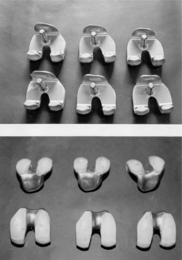
15.5.5 Example: knee prosthesis
The ceramic condyles and the metallic body of a hybrid knee prosthesis are brazed together by means number 39 filler metal. Foils 75–80 µm in thickness are used, previously heated in vacuum at 500 °C for 5 min to reduce hardness and increase ductility. The post-production examination points out some cavities at titanium/ceramic interfaces due to excessive machining clearance. As a consequence, a general rule must established, according to which clearance should not be larger than brazing foils thickness (80 µm). Non-destructive X-rays analysis shows that the brazed joint is quite uniform at the bottom horizontal contact surface, while at the 90 ° bend region, some non-brazed areas appear, due to misfitting between the parts in the as-machined conditions. To verify the homogeneity of the brazed joint, longitudinal and transverse cross-sections have to be cut, polished and analysed through optical microscopy. Metallographic investigation indicates the absence of voids, porosities and cracks. However, the onset of cracks due to intrinsic brittleness of brazing joints is one of the major concerns in industrial applications and is well documented in literature (Cannon et al., 1991; Howe, 1993; Soon-Bok et al., 1995; Waddell et al., 2007). Figures 15.25 and 15.26 point out the features of transverse and longitudinal sections respectively, and show that locations with large clearance are not sufficiently brazed. Composition and micro-structural homogeneity of brazing foils are analysed by means of an EDX Analyser in a Scanning Electron Microscope: large amounts of second-phase particles can be found, consisting of Au, Al and Ti, while the matrix is rich with Ag. However, since the areas considered are few square microns wide (owing to small size of electron beam), the analysis is not reliable in providing information about the bulk composition of the braze foil: to this purpose, wet chemical analysis method should be preferred. On the basis of these post-production analyses, the prostheses design should be optimized, enabling a better fitting between metallic and ceramic parts, to improve the integrity of the brazed joint. Besides, where clearances lie within the range 200–300 µm, a double layer of brazing foils should be used. Finally, special fixtures should be provided to hold metallic and ceramic components tightly together during brazing. On the basis of these experiences, some general rules can be established to obtain a good-quality brazed-metal/ceramic prosthesis (Murray et al., 1999):
• Tolerances in excess of about 100 µm should be avoided. Use of double layer of brazing foils helps, but not with large cavities. This has to do with the low flow properties of the braze, which reduce the capability of filling the cavities by capillary action;
• Misfits between metallic and ceramic parts are due to clearance and/or possible movements within the holding jigs at high brazing temperature. Special jigs have to designed to avoid/minimize this drawback;
• If brazing conditions are optimized, the metallic parts are shiny and the ceramic ones are free from any vapour condensation (see Fig. 15.27). In this case, the joint strength is satisfactory and the prostheses are able to withstand not only large forces occurring during machining and polishing of finished prostheses, but also simulated physiological loads (12 000 N ultimate load, 2000 N fatigue load up to 5 millions cycles – with 4.86 mg/million cycle weight loss).
15.6 Future trends
Besides active brazing technique, some other innovative processes are likely to be successfully adopted to join metals and bio-ceramics, in the field of both solid- and liquid-phase welding.
Solid-phase welds already demonstrated to be suited for joining metals and ceramic through different friction-welding processes, like ultrasonic welding and ultrasonic brazing. In ultrasonic welding, reciprocal micro-motion between the adherents is provided by ultrasonically induced vibrations. Notwithstanding ceramics have inherently poor ductility, a certain degree of plastic deformation is necessary to accomplish friction welding. Ultrasonic brazing is just an ultrasonically-assisted conventional technique, where vibrations allow to remove air bubbles from the molten filler to improve wetting and filling.
Very promising are the ‘functional graded material (FGM) joints’, which are able to join even strongly misfitting adherents through several interlayers of gradually varying metal–ceramic compositions. Combustion synthesis (CS) and self-propagating high-temperature synthesis (SHS) represent the more efficient techniques to produce graded layers. They both are exothermic brazing processes, but in SHS a progressive reaction happens, whose front sweeps through the volume of reactants, while in CS a sudden reaction occurs. The reactants consist in powders of elemental metal and oxide, placed between the adherents. The heat generation is high enough to cause substrate surface melting and to create liquid-phase products. The reactants are packed between the solid adherents (Fig. 15.28); this sandwich is then unidirectionally compressed while the reaction is ignited: as a consequence, problems may arise if non-flat, contoured surfaces have to be joined.
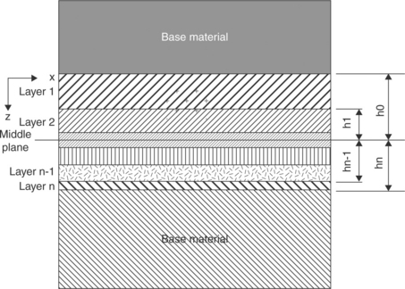
15.28 Schematic illustration of a functionally graded material (FGM) joint between a metal and a ceramic. Source: Reprinted from Messler, 2004, p. 710.
Although ceramics melt at very high temperature and induce phase transformation and cracking inside the heat-affected zone, liquid-phase techniques, especially the ones based on high-energy density process, are destined to increase their popularity. Electron-beam welding (EBW) and laser-beam welding (LBW) were already used in some cases to weld corrosion-resistant metals to oxide ceramics. Both EBW and LBW use a very high-intensity beam to produce heating and induce welding, being the energy highly concentrated by electro-magnetic or optical lens, respectively. The energy density in these processes can reach 1010–1013Wm−2, compared with 5 × 10⁸Wm−2 typical of conventional processes. The kinetic energy of electrons (EBW) and photons (LBW) is converted into heat as soon as the particles hit the adherents and cause melting and vaporization in a very localized area. Both processes are able to produce deep and narrow weld beads, as well as narrow heat-affected zones. In general, the EBW process is performed autogenously; in this case, matching between adherents surfaces should be perfect. However, when thick sections have to be welded, filler metal is needed, preferably in the form of in situ shims, since getting wire down into a deep weld is difficult. LBW is usually performed autogenously as well, but using wires as filler metal. Shielding of EBW process is guaranteed by a certain degree of vacuum (typically 10−3–10−5 bar), which is needed for allowing the electron beam to flow towards the adherents without collisions in the air. Alternatively, shielding of LBW process is accomplished by means of inert gases, which are supplied to create a non-oxidizing atmosphere in the vicinity of weld pool.
Finally, electron-beam brazing and laser-brazing processes can be used as well: the beams of electrons or photons locally heat a joint, where the filler metal is pre-placed in some form (layers, shims, rings). The main advantages of these processes consist in very rapid heating, very small thermally affected zone and accurate dimensional control. Like EBW and LBW, both laser-brazing and electron-beam-brazing processes should be shielded as well, respectively using inert atmosphere and vacuum (Messler, 2004).
15.7 Sources of further information and advice
Further information on these and related subjects can be found in the books, journals, scientific societies and technical agencies listed below:
Black, J.Biological Performance of Materials: Fundamentals of Biocompatibility. New York: Marcel Dekker, 1992.
Boretos, J.W., Eden, M.Contemporary Biomaterials: Materials and Host Response, Clinical Application, New Technologies and Legal Aspects. Park Ridge, NJ: Noyes Publications, 1984.
Messler, R.W., Jr.Principles of Welding: Processes, Physics, Chemistry and Metallurgy. New York: John Wiley & Sons, 1999.
Park, J.B.Biomaterials: An Introduction. New York: Plenum, 1979.
Park, J.B.Biomaterials Science and Engineering. New York: Plenum, 1984.
Schwartz, M.M.Ceramic Joining. Materials Park, OH: ASM International, 1990.
Advanced Materials and Processes (ASM)
American Ceramic Society Bulletin (American Ceramic Society)
Biomaterials (including Clinical Materials) (Elsevier)
Biomaterials Forum (Society for Biomaterials)
Biomaterials: Processing, Testing and Manufacturing Technology (Butterworth)
Biomedical Materials (Elsevier)
Biomedical Materials in Engineering (Pergamon Press)
British Ceramics Transactions and Journal (Institute for Ceramics)
Ceramic Forum International (Deutsche Deramische Geselleschaft)
Ceramics Abstract (American Ceramic Society)
Journal of the American Ceramic Society (American Ceramic Society)
Journal of Biomaterials Applications (Technomics)
Journal of Biomedical Materials Research (Wiley)
Journal of Biomedical Materials Research: Applied Biomaterials (Wiley)
Journal of Engineering in Medicine (Institution of Mechanical Engineers)
Journal of Material Science (Springer)
Materials in Medicine (Chapman & Hall)
Materials Science and Engineering (Elsevier)
Medical Device Research Report (Association for the Advancement of Medical Instrumentation)
15.8 References
Atabaki, M.M. Recent progress in joining of ceramic powder metallurgy products to metals. Metalurgija. 2010; 16(4):255–268.
Barbosa, M.A.Biomaterials: Hard Tissue Repair and Replacement. London: Elsevier-Science North-Holland, 1992.
Blischak, B.R. System and method for making an implantable pump thinner, 2011. [United States Patent No. US 7,896,866 B1].
Cannon, R.M., Dalgleish, B.J., Dauskardt, R.H., Oh, T.S., Ritchie, R.O. Cyclic fatigue-crack propagation along ceramic/metal interfaces. Acta Metallurgica et Materialia. 1991; 39(9):2145–2156.
Carim, A.H., Schwartz, D.S., Silberglitt, R.S.Joining and Adhesion of Advanced Inorganic Materials. Warrendale, PA: Materials Research Society, 1993.
Chandler, J.E., Messer, H.H., Ellender, G. Cytotoxicity of gallium and indium ions compared with mercuric ion. Journal of Dental Research. 1994; 73(9):1554–1559.
Chiao M., Chiao J.C., eds. Biomaterials for MEMS. Singapore: Pan Stanford Publishing Pte Ltd, 2011.
Cooper, J.R., Caravia, L., Dowson, D., Fisher, J. Ceramic bearing surfaces in total artificial joints. Journal of Medical Engineering Technology. 1991; 15:63–67.
Daulton, J. Self-centering braze assembly methods, 2010. [United States Patent No. US 7,766,216 B2].
Fowler, B.C., Miazga, J., Bielstein, M.L. Implantable medical devices and associated systems and methods, 2010. [United States Patent No. US 2010/0185268 A1].
Hallab, N.J., Jacobs, J.J., Katz, J.L. Orthopedic application. In: Ratner B.D., Hoffman A.S., Schoen F.J., Lemons J.E., eds. Biomaterials Science. London: Elsevier Academic Press; 2004:527–556.
Haller, M.I., He, T.X., Daulton, J. Assembly for a microstimulator, 2010. [United States Patent No. US 7,781,683 B2].
He, T.X., Colvin, M.S. Hermetically bonding ceramic and titanium with a Ti-Pd braze interface, 2010. [United States Patent No. US 7,771,838 B1].
Hench, L.L. Bioceramics: from concept to clinic. Journal of the American Ceramic Society. 1991; 74:1487–1510.
Hench, L.L., Best, S. Ceramics, glasses and glass-ceramics. In: Ratner B.D., Hoffman A.S., Schoen F.J., Lemons J.E., eds. Biomaterials Science. London: Elsevier Academic Press; 2004:153–170.
Hench, L.L., Ferber, M.K., Tennery, V.J. Structural applications for technical, engineering and advanced ceramics: medical and scientific products. In: Schneider S.J., ed. Engineered Materials Handbook: Ceramics and Glasses. Materials Park, OH: ASM International; 1991:1007–1014.
Hench, L.L., Wilson, J. Bioceramics. MRS Bulletin. 1991; 16:62–74.
Hench, L.L., Wilson, J.An Introduction to Bioceramics. Singapore: World Scientific Publishing, 1993.
Howe, J.M. Bonding, structure and properties of metal/ceramic interfaces: Part 2 Interface fracture behaviour and property measurement. International Materials Reviews. 1993; 38(5):257–271.
Iijima, S. Histopathological study of the effect of pure metals to the periodontal tissues. Nihon Shishubyo Gakkai Kaishi. 1989; 31(4):997–1020.
Jiang, G., Mishler, D., Davis, R., Mobley, J.P., Schulman, J.H. Zirconia to Ti-6Al-4Va braze joint for implantable biomedical device. Journal of Biomedical Materials Research Part B: Applied Biomaterials. 2005; 72B:316–321.
Kamachimudali, U., Sridhar, T.M., Baldev, R. Corrosion of bio implants. Sadhana (Indian Academy Proceedings in Engineering Sciences). 2003; 28(3–4):601–637.
Kimura, Y. Effects of indium and tin addition to Ag-Cu alloys on the biocompatibility. Gifu Shika Gakkai Zasshi. 1988; 15(2):366–391.
Koch, K.P. Neural prostheses and biomedical microsystems in neurological rehabilitation. Acta Neurochir. Suppl.. 2007; 97(1):427–434.
Loehman, R.E., Tomsia, A.P. Joining of ceramics. Ceramic Bulletin. 1988; 67:375–384.
Messler, R.W., Jr.Joining of Advanced Materials. Burlington, MA: Elsevier/Butterworth-Heinemann, 1993.
Messler, R.W.Joining of Materials and Structures. Oxford: Elsevier/Butterworth-Heinemann, 2004.
Murray, M.G.S., Facchini, A., Sicking, R., Specchia, N., Pathiraj, B., Gomez, A., Sala, G. Development of an advanced ceramic/titanium alloy knee joint. Procs. Bioceramics. 1999; 12:1114–1122. [Nara, Japan].
Nicholas, M.G. Active metal brazing. Br. Cram. Trans. J.. 1986; 85:144–155.
Nicholas, M.G., Crispin, R.M. Brazing ceramics with alloys containing titanium. Ceram. Eng. Sci. Proc.. 1989; 10:1602–1610.
Paiva, O.C., Barbosa, M.A. Production, bonding strength and electrochemical behaviour of commercially pure Ti/Al2O3 brazed joints. Journal of Materials Science. 1997; 32:653–659.
Pask, J.A. From technology to the science of glass/metal and ceramic/metal sealing. Ceramic Bulletin. 1987; 66:1587–1593.
Pope, M.H., Fleming, B.C. Knee biomechanics and materials. In: Laskin R.S., ed. Total Knee Replacement. London: Springer Verlag; 1991:25–38.
Sicking, R.Beitrag zur entwicklung eines biokompatiblen aktivlotes zum fugen von oxidkeramik an TiAl6V4. Aachen: Shaker Verlag, 2000.
Soon-Bok, L., Kobayashi, H., Huh, J.W. Fatigue strength and fracture mechanism of ceramic-metal joints under cyclic bending. International Journal of Fatigue. 1995; 17(6):427–435.
Tomsia, A.P., Pask, J.A., Loehman, R.E. Joining. In: Schneider S.J., ed. Engineered Materials Handbook: Ceramics and Glasses. Materials Park, OH: ASM International; 1991:477–546.
Tziviskos, G. Hermetic seal, 2010. [United States Patent N ° US 7,837,085 B1].
Waddell, J.N., Ichim, I., Lee, H., Fangtao, L., Payna, A.G.T., Swain, M.V. Fatigue failures of bar-attachment brazed joints for implant-supported overdentures. Engineering Fracture Mechanics. 2007; 74(7):1148–1159.
Wataha, J.C., Nakajima, H., Hanks, C.T., Okabe, T. Correlation of cytotoxicity with elemental release from mercury- and gallium-based dental alloys. in vitro’, Dental Materials. 1994; 10(5):298–303.
Xiaochun, L., Xugang, Z., Werschmoeller, D., Hongseok, C., Xudong, C. Embedded micro/nano sensors for harsh engineering environments. Sensors – 2008 IEEE. 2008; 127:3–1276.