
Joining of platinum (Pt) alloy wires to stainless steel wires for electronic medical devices
Abstract:
The joining of dissimilar materials in medical-device applications is necessary to increase flexibility in design, enhance performance, and reduce material costs. This chapter will discuss the joining of platinum alloy wires to stainless steel wires in the crossed-wire joint configuration, providing a solid introduction to the challenges that accompany the joining of dissimilar materials in non-standard joint geometries. Example studies utilizing the resistance microwelding and laser microwelding processes are provided along with the process conditions required to produce sound joints.
6.1 Introduction
The microwelding of dissimilar crossed-wire materials is becoming increasingly important for making electrical interconnections in medical devices.1, 2 Joining dissimilar materials allows for more flexibility in design, enhanced performance, and reduction in material costs. For example, the joining of platinum (Pt) alloys to stainless steel (SS) is necessary to reduce costs by using less Pt material as well as utilizing the excellent corrosion resistance, electrical properties, and biocompatibility of Pt alloys along with the superior mechanical properties of SS. Some common applications where Pt alloys require joining to SS alloys can be found in medical devices such as pacemakers, defibrillators, and cochlear implants, where Pt alloys are commonly used for electrodes and battery/capacitor feed through terminals which require joining to SS wire leads.3,4 Dissimilar-materials joining and the crossed-wire configuration, however, pose several welding-related challenges, all of which are commonly experienced in the manufacturing of medical devices. Two of the most common microwelding processes used in the welding of medical devices include resistance microwelding (RMW) and laser microwelding (LMW). In this chapter, both RMW and LMW of Pt alloy wires to stainless steel (SS) wires are discussed. Typical joint morphology with respect to welding parameters will be outlined along with the techniques and parameter sets used to obtain sound dissimilar crossed-wire joints.
6.2 Material properties
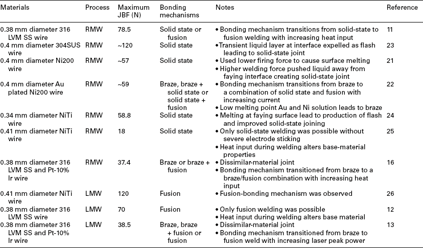
Materials used in medical-device applications are required to be tough, durable, corrosion resistant, and, most importantly, biocompatible. Failure to meet these requirements can cause serious harm to the patient, the need for corrective surgery, or even death. Pt alloys (i.e., commercially pure Pt, Pt-Ir, etc.) and SS alloys (i.e., 303, 304, 316, etc.) have been extensively used in the medical industry for many different applications ranging from microelectronic connections in pacemakers to surgical tools.5, 7, 8 Material properties of the most common Pt and SS alloys used in the medical industry are given in Table 6.1 for aid in discussion.

Platinum and its alloys are well suited for medical applications due to excellent biocompatibility and mechanical properties. Platinum is classified as a noble metal, meaning it is resistant to both corrosion and oxidation. Hypoallergenic reactions to Pt alloys are rare and they have been long proven as passive-type biomaterials, making them ideal for both temporary and permanent implantation applications.5, 6 Platinum also has excellent processability where it can be easily fabricated into very small and complex components. Platinum is often alloyed with iridium (Ir) in order to improve the mechanical properties of the material such as tensile strength.9 The major drawback to Pt alloys is high cost because Pt is a precious metal. For this reason many medical applications are exploring new biomaterials and designs to limit the amount of Pt used in order to reduce material costs.
Austenitic stainless-steel (SS) alloys are commonly used in medical applications and have been considered the baseline for implantable medical-device materials. Stainless steel has a relatively low cost compared with other biocompatible metals, excellent mechanical properties, good corrosion resistance and excellent processability.9 The corrosion and oxidation resistance of SS alloys are attributed to a passive Cr oxide layer on the surface of the material. Stainless steel does, however, still have the tendency to corrode in the human body due to being exposed to complicated aggressive fluids containing chloride ions and amino acids, as well as cells and proteins, causing the Cr oxide layer to locally break down.9, 10 The release of Ni ions into the body during the corrosion of SS alloys is undesirable since they are known to be toxic and can cause hypoallergenic reactions.8, 10
6.3 Material challenges in joining
In materials joining the ultimate goal is to join two components where the joint has the same properties as the base material and the base-material properties are not affected by the joining process. This, however, would be an ideal situation and unfortunately is generally not feasible. In this section the effects of heat input on base-material properties along with the challenges associated with dissimilar material joining of Pt and SS alloys are discussed.
6.3.1 Effects of material properties on joint formation
The electrical and thermal properties of the dissimilar materials play a large role in the joint formation during microwelding. Pt alloys and SS alloys have significantly different thermal and electrical properties which lead to complications during both RMW and LMW, as will be discussed in more detail in subsequent sections. For example the difference in liquidous temperatures between Pt-10% Ir and 316 LVM SS is approximately 200–300 K and thermal conductivity of Pt-10% Ir is four times greater. This means the applied heat during welding will dissipate faster in the Pt alloy making the SS alloy even more susceptible to melting. Hence, these differences in material properties will play a large role in the bonding mechanism and must be taken into account prior to selecting joining process steps and joint geometry.
6.3.2 Thermal effects on base materials
Material properties can be altered during microwelding which can degrade the properties of the base material (BM) obtained through previous material-processing steps. Changes in material properties are attributed to the thermal cycles experienced during welding. Peak temperatures reached during the joining process can induce diffusion leading to the production of different phases or cause recrystallization and growth of grains altering the prior base-metal microstructure. The final microstructure is usually softer and can have substantially different mechanical properties when compared with the unaffected BM. In joining Pt to SS crossed-wires changes in microstructure in the heat-affected zone (HAZ) adjacent to the crossed-wire joint can decrease the material strength by destroying the cold-worked structure obtained during the wire-drawing process. Khan et al.11, 12 showed a reduction in hardness and therefore strength in the HAZ of 316 LVM SS crossed-wire RMW and LMW welds. This reduction in strength leads to the fracture of the joint through the HAZ during tensile testing. Zou et al.13 showed similar HAZ softening in the LMW of Pt-10% Ir to 316 LVM SS crossed-wires as shown in Figs 6.1 and 6.2. However, the Pt-10% Ir wire was in the annealed condition before welding therefore the decrease in Vickers hardness was not nearly as pronounced in the HAZ. Also, note the solidification structure in the fusion zone (FZ) which contains both Pt-Ir and SS has higher hardness than the Pt BM.
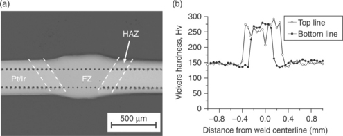
6.1 Microhardness tests performed on 0.39 kW LMW joint cross-sectioned along the Pt–Ir wire axis direction; (a) optical image of sample and (b) Vickers hardness results. With kind permission from Springer Science+Business Media: Metallurgical Materials Transactions A, Crossed-wire laser microwelding of Pt-10 pct Ir to 316 low-carbon vacuum melted stainless steel: Part I. Mechanism of joint formation, 43(4), 2012, p. 1223, G. S. Zou, Y D. Huang, A. Pequegnat, X. G. Li, M. I. Khan, Y Zhou, Figure 12.

6.2 Microhardness tests performed on 0.35 kW LMW joint cross-sectioned along the SS wire axis direction; (a) optical image of sample and (b) Vickers hardness results. With kind permission from Springer Science+Business Media: Metallurgical Materials Transactions A, Crossed-wire laser microwelding of Pt-10 pct Ir to 316 low-carbon vacuum melted stainless steel: Part I. Mechanism of joint formation, 43(4), 2012, p. 1223, G. S. Zou, Y D. Huang, A. Pequegnat, X. G. Li, M. I. Khan, Y Zhou, Figure 13.
6.3.3 Effects of intermetallics formation
In joining dissimilar-materials, defects in the welded joint such as cracking, porosity, and intermetallic compounds (IMCs) are more likely to occur due to mixing of different elements either by diffusion or in the molten weld pool.17 Intermetallics are notoriously brittle and are often cited as the limiting factor when considering maximum joint strength in dissimilar welds. For example, in laser welding dissimilar Pt and Ti materials, brittle IMCs (i.e., Ti3Pt5, TiPt3 and Ti3Pt) could not be avoided and were attributed to cracking in the joint.17, 18 In joining Pt to SS there are also several possible IMC compounds that can be identified from phase diagrams.19 However, these IMCs were not found to play a large role in joint strength. Chen et al.20 observed the RMW joint between 316L SS blocks and Pt wires failing in the Pt wire rather than through regions at the joint interface where IMC compounds reside. Also, in work by Zou et al.13 and Huang et al.15, 16 LMW and RMW crossed-wire joints between Pt-10% Ir and 316 LVM SS wires were found to fail in the Pt-10% Ir wire at the maximum achievable JBF. Therefore, in the joining of Pt and SS alloys IMCs are likely present but do not significantly degrade joint strength.
6.3.4 Effects of welding on corrosion resistance
The corrosion-resistant properties of SS that are vital for implantable device applications can also be affected in the HAZ. Welding SS alloys increases the susceptibility of corrosion in Austenetic SS alloys by weld decay where the grain boundaries adjacent to the weld can become depleted of Cr and corrosion can occur more easily.14 Therefore, the amount of heat produced in the joint must be limited in order not to alter the corrosion resistance of the SS base material. Low-carbon steels such as 316 LVM are often used in medical applications to reduce the susceptibility of forming Cr carbides and therefore weld decay.
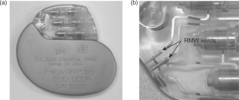
In joining dissimilar materials such as Pt alloys to SS alloys a galvanic couple is also created at the joint. In an implantable medical device the joint must therefore be shielded from the corrosive environment in the body usually by encapsulation in epoxy or hermetic sealing in a titanium can. Figure 6.3 shows a pacemaker where epoxy is used to seal RMW joints between lead connector ribbons and feed through terminals. The galvanic couple between Pt-10% Ir and 316 LVM SS wires prevented etching of joint metallographic cross-sections in References 13, 15, and 16 where extensive pitting of the 316 LVM SS wire material could not be avoided. This further highlights the importance of considering corrosion resistance when joining dissimilar materials such as Pt and SS.
6.4 The crossed-wire joint
In medical applications many different joint geometries are necessary to achieve the required flexibility in design. The crossed-wire joint geometry is most commonly used for electrical connections in medical devices or for structural members including coronary stents.1, 21 Example RMW and LMW 316 LVM SS crossed-wire welds are shown in Fig. 6.4.11, 12 Several researchers have investigated the microwelding of thin (i.e., 200–500 µm) crossed-wires using both RMW11, 21–25 and LMW12, 26 for various different materials. However, the focus has been predominantly on joining similar materials with the exception of Zou et al.13 and Huang et al.15, 16 who focus on the dissimilar crossed-wire joining of Pt-10% Ir and 316 LVM SS. A brief summary of several past crossed-wire microwelding studies is provided in Table 6.2.
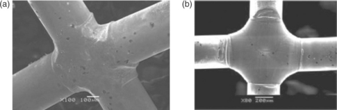
6.4 (a) SEM image of 316 LVM crossed wire RMW joint (With kind permission from Springer Science+Business Media: Metallurgical MaterialsTransactions A, Bonding mechanisms in resistance microwelding of 316 low-carbon vacuum melted stainless steel wires, 40(A), 2009, p. 910, M. I. Khan, J. M. Kim, M. L. Kuntz, Y. Zhou, Figure 15a). (b) SEM image of 316 LVM crossed wire LMW joint. (Reprint with permission of ASM International. All rights reserved. www.asminternational.org.)
6.4.1 Joint-quality characterization
The crossed-wire joint is characterized by its geometry, appearance, and strength. First the joint is inspected for defects such as surface pores, weld spatter, cracks, notches, contamination (i.e., by electrode in RMW), or necking. Poor surface quality is unacceptable in medical-device applications due to a reduction in joint reliability and the possibility of electrical shorts, uneven current transport through the joint, contamination, or even damage to living tissue. The surface quality is usually assessed by either optical microscopy or scanning electron microscopy (SEM). Weld cross-sections are also observed to identify hidden defects inside the joint itself. Some of these defects include internal pores and cracks.
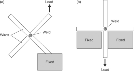
Defects such as porosity, cracks, necking, or notches reduce the integrity of the joint in both maximum strength and fatigue performance. The strength of crossed-wire joints is commonly measured by tensile testing where the joint is subject to a tensile shear loading condition until failure occurs. The force at which the crossed-wire joint fails has been termed joint breaking force (JBF). The two most common methods for measuring the JBF are illustrated in Fig. 6.5. The 45 ° tensile-test method is harsher since it adds a bending stress to the wires putting additional strain on the crossed-wire joint.
6.5 Joining processes
As previously mentioned the most common welding processes used for joining metals in the medical industry are RMW and LMW. Both of these methods are capable of producing crossed-wire joints between the dissimilar Pt and SS alloys. In this section the RMW and LMW joining processes will be introduced and the specific challenges in joining Pt to SS crossed-wires will be addressed. The bonding mechanisms with respect to welding parameters will be outlined along with the techniques and parameter sets used to obtain sound dissimilar crossed-wire joints.
6.5.1 Resistance microwelding (RMW)
Resistance microwelding is widely used in the medical industry since it is an economical process that offers excellent reliability and productivity with relatively low capital costs.2 There are major differences in RMW compared with large-scale resistance spot welding (LSRSW). Some of these differences include substantially lower welding forces and currents, non-ferrous materials are often welded, electrode cooling is not possible and much faster cooling rates exist.2, 27–29 Zhou et al.21 and Ely and Zhou29 were among the first to investigate the differences in RMW compared with LSRSW and outline the recommended process parameters to join thin Al, brass, Cu, Kovar, steel, and Ni sheets. Many investigations into the bonding mechanism and dynamic resistance during the RMW of similar non-ferrous thin sheets and fine wires have since been performed.11–13, 15, 16, 21–26, 30–34
In the RMW process the heat required to form a joint between two metals is generated by resistive heating. The heat generated during the RMW process can be approximated by the following equation:
where the current (I) and the time (t) are controlled variables of the RMW process.35 The resistance (R) is the sum of the contact resistance at the electrode/wire interfaces, the wire/wire interface and the bulk resistances of the base materials. A schematic illustration of RMW crossed-wire joining is shown in Fig. 6.6. Crossed-wire welding is often compared to projection welding since the contact area between the two wires is very dynamic, meaning it changes drastically throughout the welding process.36 The balance between applied electrode force which directly influences the contact area at the faying interface and the welding current is therefore very critical in generating the correct amount of heat to create a sound joint. The increase in joint area during welding can be quantified by calculating the percent setdown with the following equation:
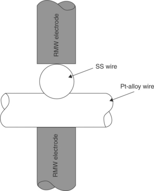
6.6 Schematic illustration of the crossed-wire RMW process.16
where A and B are defined in Fig. 6.7.21 In crossed-wire RMW the JBF increases with setdown because of an increase in joint area that results from higher heat input. However, once the heat input reaches a certain threshold a softening in the HAZ has been found to take over.21 Therefore, increasing heat input leads to a competition between two counterbalancing phenomena, increasing interfacial bond strength and wire softening, which improve and degrade joint strength respectively. The sum of their effects determines the actual joint strength.25
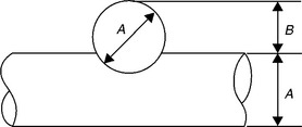
6.7 Schematic illustration of setdown in crossed-wire joining. (With kind permission from Springer Science+Business Media: Metallurgical Materials Transactions A, Mechanism of resistance microwelding of crossed fine Nickel wires, 35A, 2004, p. 3165, S. Fukumoto, Y. Zhou, Figure 3(b).)
During RMW of dissimilar material crossed-wires the main challenges arise from the difference in electrical resistivity, melting temperature, and thermal conductivity.12,16, 20 Chen20 found that the current required for melting Pt is approximately seven times greater than that required to melt SS. This means at a fixed weld current and weld time, the volume of melted SS produced is around seven times greater than that of melted Pt.20 During the RMW welding of Pt-10% Ir and SS wire defects such as weld spatter, electrode sticking, and the formation of notches in the SS wire all result from the dissimilar material properties of the two wire materials leading to unbalanced heating. Unbalanced heating shifts the location of maximum heat generation away from the desired location, the faying interface between the two wires.
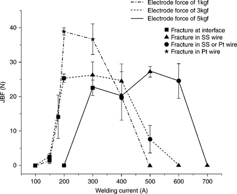
At low welding forces (i.e., < 3 kgf) Huang et al.16 observed excessive expulsion and electrode sticking when joining Pt-10% Ir and 316 LVM SS wires as shown in Fig. 6.8. The excessive melting of the SS wire at the electrode/wire interface causes this expulsion and electrode sticking. At higher electrode forces (i.e., > 3 kgf) the process window for welding currents was found to increase as a result of cold deformation increasing the contact area of the faying and electrode/wire interfaces. Higher electrode forces help avoid expulsion and electrode sticking; however, due to the crossed-wire geometry, softening of the SS wire and high electrode force, a notch in the SS wire was formed as shown in Fig. 6.9a and 6.9b.16 The JBF measured during single pulse RMW of Pt-10% Ir crossed wire welds are shown in Fig. 6.10.16 At higher electrode forces (i.e., > 3 kgf) the lower JBF values are attributed to a combination of insufficient heat input and notch defects. A maximum JBF of 38.8 N which is 90% of the 43 N (i.e., 379 MPa) tensile strength of the Pt-10% Ir wire was obtained with a 1 kgf electrode force and 200 A welding current. The weld geometry and excessive electrode sticking were, however, deemed unacceptable for all single-pulse RMW welds regardless of the maximum achievable JBF.16

6.8 Top (a) and bottom (b) view of RMW crossed-wire joints made between Pt-10% Ir and 316 LVM SS welded with electrode force of 1 kgf and current of 200 A. Electrode sticking and expulsion observed as a result of excessive melting of the SS wire.16 Reproduced with permission of Maney Publishing, Science and Technology of Welding and Joining, www.maneypublishing.com/journals/stw.
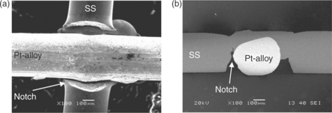
6.9 SEM images of RMW crossed-wire joints made between Pt-10% Ir and 316 LVM SS welded with electrode force of 5 kgf and current of 400 A. Bottom view (a) and weld cross-section (b) showing notch defect.16 Reproduced with permission of Maney Publishing, Science and Technology of Welding and Joining, www.maneypublishing.com/journals/stw.
6.10 Joint breaking force for single-pulse RMW Pt-10% Ir to 316 LVM SS crossed-wire joints.16 Reproduced with permission of Maney Publishing, Science and Technology of Welding and Joining, www.maneypublishing.com/journals/stw.
Double pulse RMW
As discussed in the previous section, Huang et al.16 found the traditional methods of balancing the electrode force and welding current to be insufficient in joining dissimilar Pt alloys to SS alloys in the crossed-wire configuration.16 In LSRSW, several different techniques have been employed to shift the location of maximum heat input to the desired location at the faying interface when joining dissimilar materials or sheets of different thickness. The most common of these techniques include using electrodes with different geometries, water cooling one electrode,37, 38 using electrodes with different resistances,37 or by modifying the welding schedule for example using multiple pulses.39, 40 Modifying the welding schedule is the most practical for the RMW process because using electrodes of different geometries or electrode cooling is not feasible,2 and the significant difference in workpiece properties cannot be overcome by simply changing the resistance of the electrodes.16
Huang et al.16 developed a double-pulse welding schedule capable of producing sound Pt-10% Ir to 316 LVM SS crossed-wire joints. The double-pulse welding schedule used is show in Fig. 6.11. The double-pulse welding schedule is designed to pre-deform the wires by hot deformation in the first pulse, where no melting occurs. This reduces contact resistance at the electrode/wire interface and causes the change in area at the faying surface to be less dynamic as in sheet to sheet welding. The second pulse uses a lower weld force and higher welding current to cause sufficient melting to create a brazed joint at the faying surface and also heal any cracks or notches. Scanning electron micrograph images of double pulse RMW crossed-wire welds are shown in Fig. 6.12. No expulsion, cracks or notches are observed and excessive electrode sticking was avoided. A maximum JBF of 37.4 N, 87% of the tensile strength of Pt-10% wire was achieved.16
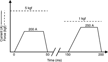
6.11 Double pulse RMW welding schedule for joining 0.38 mm dissimilar Pt-10% Ir to 316 LVM SS wires.
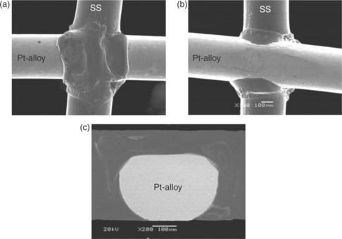
6.12 SEM images of double pulsed RMW of Pt-10% Ir to 316 LVM SS crossed-wire joints: (a) top view, (b) bottom view, and (c) cross-section.16 Reproduced with permission of Maney Publishing, Science and Technology of Welding and Joining, www.maneypublishing.com/journals/stw.
Bonding mechanism during RMW
When joining similar crossed-wire materials using the RMW process the joining mechanism predominantly transitions from solid-state to fusion with increasing heat input, as shown in References 11, 21, and 23–25. Resistive heating at the faying interface causes surface melting at the interface. The molten metal at the interface is squeezed out due to the electrode force. This cleans the interface by removing any surface contaminants, improving the surface conditions for crystallographic matching and interdiffusion of atoms across the interface, promoting quality solid-state bonding. With increasing heat input the solid-state bond increases in strength as the setdown increases and the bond area grows. This additional heat also promotes new grains to grow across the interface via recrystallization.21 At even higher heat inputs fusion can occur. However, fusion welding in RMW crossed-wire bonding is often accompanied by expulsion, electrode sticking, and recrystallization and grain growth in the HAZ. Therefore, when fusion occurs it is usually considered overwelding which should be avoided.21, 25
In joining dissimilar wire materials such as Pt-10% Ir to 316 LVM SS the bonding mechanism is predominantly brazing or a combination of brazing and fusion.16 The brazing mechanism only occurs due to the large difference in melting temperatures between the two wire materials to be joined. For brazing only one of the materials becomes molten while the other remains a solid. In joining Pt-10% Ir and 316 LVM SS wires the 200–300 K lower melting point of the SS and the four times larger thermal conductivity leads to the SS material melting at a much lower heat input than the Pt-Ir wire causing wetting and the braze-type joint shown in Figs 6.8, 6.9 and 6.12.16 Similar results were observed by Fukumoto et al.22 in crossed-wire welding Au-coated Ni wires where, at low welding currents, insufficient heat was produced to melt the Ni wires but a brazed joint was created when the Au coating melted (i.e., > 1064 °C) at the interface. Also, a low melting point (i.e., > 955 °C) Ni-Au solution was also identified which acts as a braze melting at temperatures below that of pure Ni.
6.5.2 Laser microwelding (LMW)
Laser microwelding is a very attractive process in the medical industry having a number of advantages over RMW. Some of these advantages include high precision due to the small size of the laser spot, non-contact to workpiece preventing contamination, excellent weld quality with low heat input and the laser process is easily automated.17, 41 Laser equipment is also a lot more affordable following a drop in cost over the last two decades.17 Laser microwelding also has advantages when joining dissimilar materials as the difference in electrical resistance between the two different materials is not an issue and complete melting of only one material creating a braze-type joint is possible without expulsion and electrode sticking.1, 13 Pulsed neodymium-doped yttrium aluminum garnet (Nd:YAG) type lasers are commonly used in medical joining applications. Nd:YAG lasers have an average output power of 0.3–3 kW and a wavelength of 1064 nm, and can easily achieve a spot size of 200 µm.17, 42 Metals have a relatively low reflectivity at 1064 nm, therefore lower powers are required for welding due to the majority of laser energy being absorbed.42
In crossed-wire LMW a welding fixture is used to apply pressure on the top wire producing the intimate contact required for laser welding as well as promoting setdown. Examples fixture used for crossed-wire LMW are shown in Fig. 6.13a and 6.13b.13, 26 In the fixture shown in Fig. 6.13b used for crossed-wire joining of Pt-10% Ir to 316 LVM SS a hole in the fixture is located beneath the weld location is necessary to prevent welding of the wires to the fixture.13 Zou et al.13 found the optimized hole size to have a depth H of 1 mm and a diameter Φ of 1 mm in order to achieve acceptable joint geometries with acceptable setdown. Example LMW 316 LVM SS and NiTi alloy crossed-wire welds are shown in Figs 6.4b and 6.14, respectively.12, 26
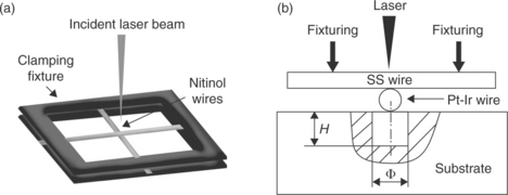
6.13 Example of LMW fixtures for crossed-wire welding. Two different types of crossed wire joining fixtures. (a) With kind permission from Springer Science+Business Media: Metallurgical Materials Transactions A, Mechanical and functional properties of laser-welded Ti-55.8 wt pct Ni Nitinol wires, 42(8), 2012, p. 2166, B. Tam, M. I. Khan, Y. Zhou, Figure 1. (b) With kind permission from Springer Science+Business Media: Metallurgical Materials Transactions A, Crossed-wire laser microwelding of Pt-10 pct Ir to 316 low-carbon vacuum melted stainless steel: Part I. Mechanism of joint formation, 43(4), 2012, p. 1223, G. S. Zou, Y. D. Huang, A. Pequegnat, X. G. Li, M. I. Khan, Y Zhou, Figure 1.
6.14 Crossed-wire NiTi LMW. With kind permission from Springer Science+Business Media: Metallurgical Materials Transactions A, Mechanical and functional properties of laser-welded Ti-55.8 wt pct Ni Nitinol wires, 42(8), 2012, p. 2166, B. Tam, M. I. Khan, Y. Zhou, Figure 14(a).
In laser welding dissimilar materials the best material combinations for weldability are materials that have good solubility and similar thermal properties. Materials combinations with large differences in thermal properties generally have poor weldability due to excessive vaporization of one of the materials and formation of brittle IMCs.42 As mentioned previously, Pt alloys have a 200–300 K lower melting point and four times lager thermal conductivity compared with the SS alloys. Therefore, joining Pt alloys to SS alloys is expected to be challenging and a fusion-bonding mechanism may not be ideal.
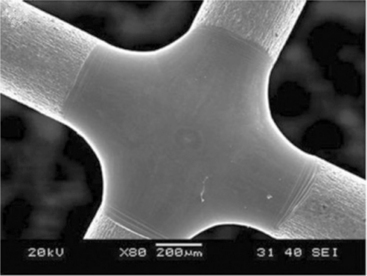
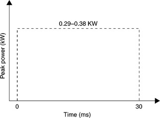
When joining 0.38 mm diameter Pt-10% Ir and 316 LVM SS wires, Zou et al.13 found a maximum JBF of 38.5 N could be achieved with peak laser powers between 0.29 and 0.38 kW, 30 ms pulse duration, and a square pulse profile as shown in Fig. 6.15. The JBF obtained at each peak power is shown in Fig. 6.16. This maximum JBF is 90% of the strength of the annealed Pt-10% Ir wire and the joint geometry and surface condition were considered to be excellent. Example welds made with a peak power of 0.35 kW are shown in Fig. 6.17.13
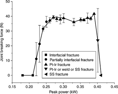
6.16 JBF for LMW Pt-10% Ir to 316 LVM SS crossed-wire joints. With kind permission from Springer Science+Business Media: Metallurgical Materials Transactions A, Crossed-wire laser microwelding of Pt-10 pct Ir to 316 low-carbon vacuum melted stainless steel: Part I. Mechanism of joint formation, 43(4), 2012, p. 1223, G. S. Zou, Y. D. Huang, A. Pequegnat, X. G. Li, M. I. Khan, Y. Zhou, Figure 14(b).
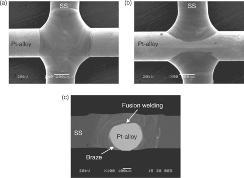
6.17 LMW Pt-10% Ir to 316 LVM SS crossed-wire joints made with 0.35 kW peak power: (a) top of joint; (b) bottom of joint and (c) joint cross-section. With kind permission from Springer Science+Business Media: Metallurgical Materials Transactions A, Crossed-wire laser microwelding of Pt-10 pct Ir to 316 low-carbon vacuum melted stainless steel: Part I. Mechanism of joint formation, 43(4), 2012, p. 1223, G. S. Zou, Y. D. Huang, A. Pequegnat, X. G. Li, M. I. Khan, Y. Zhou, Figures 4(c1,c2) and 10(a).
Bonding mechanism during LMW
As shown in Figs 6.4b and 6.14, for crossed-wire LMW of similar materials a fusion-type bonding mechanism is desirable, yielding excellent joint geometry and JBF.12, 26 However, in joining Pt alloys to SS alloys, complete fusion welding must be avoided to prevent porosity and IMC formation due to the substantial differences in thermal properties of the two materials and solubility of the alloying elements. Complete fusion welding was considered overwelding when joining Pt-10% Ir to 316 LVM SS and pores are easily observed both on the surface and within welds made with peak laser powers above 0.4 kW as shown in Fig. 6.18a and 6.18b.13 Zou et al. found that a braze-type bonding mechanism is to be desired.13, 15 In Fig. 6.17c it can be seen that there is limited mixing (i.e., fusion welding) between the Pt wire and the SS wire in the joint cross-section. A combination of fusion welding at the top of the Pt-Ir and brazing at the bottom of the Pt-Ir wire was found to be ideal.
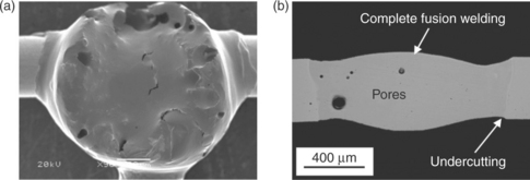
6.18 Examples of overwelded LMW Pt-10% Ir to 316 LVM SS crossed-wire joints: (a) joint surface and (b) joint cross-section. With kind permission from Springer Science+Business Media: Metallurgical Materials Transactions A, Crossed-wire laser microwelding of Pt-10 pct Ir to 316 low-carbon vacuum melted stainless steel: Part I. Mechanism of joint formation, 43(4), 2012, p. 1223, G. S. Zou, Y. D. Huang, A. Pequegnat, X. G. Li, M. I. Khan, Y. Zhou, Figures 4(f1) and 11(b).
Importance of wire orientation in LMW
The joint formation for the dissimilar crossed-wire welds is greatly influenced by the temperature gradient in the joint during welding, as well as by the properties of the wire materials being joined. Since the material properties of Pt and SS are quite different, a large difference in joint morphology and quality can be realized by subjecting the higher melting point and larger thermal conductivity Pt wire to the incident laser beam (i.e., Pt wire on top). Huang et al.15 were not able to produce a sound crossed-wire joint between Pt-10% Ir and 316 LVM SS wire when the Pt-Ir wire was subject to the incident laser beam. A unique form of porosity was identified only in a mixed zone (MZ) where the molten SS material mixed with the molten Pt-Ir material as shown in Fig. 6.19.15 The MZ forms due to a combination of the wire orientation, geometry of the joint and the difference in thermal properties of the materials. The temperature gradient across the joint can be deduced by observing this unique sample cross-section and considering the three distinct regions, namely the MZ (top), the Pt-Ir region (middle), and the SS region (bottom). In the MZ the temperature must be the highest as the high melting point Pt-Ir wire is melted via direct interaction with the incident laser beam. In the middle of the weld the Pt-Ir wire does not reach a high enough temperature to melt. However, at the bottom of the weld, the lower melting point SS wire melts via thermal conduction through the wires causing it to wet the whole joint creating a braze-type joint and the MZ.
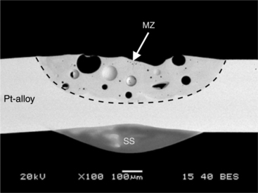
6.19 Cross-section of Pt-10% Ir to 316 LVM SS crossed-wire LMW joint where the Pt-Ir wire was subject to the incident laser beam. With kind permission from Springer Science+Business Media: Metallurgical Materials Transactions A, Crossed-wire laser microwelding of Pt-10 pct Ir to 316 low-carbon vacuum melted stainless steel: Part II. Effect of orientation on joining mechanism, 43(4), 2012, p. 1234, Y. D. Huang, A. Pequegnat, G. S. Zou, J. C. Feng, M. I. Khan, Y. Zhou, Figure 7(d).
Huang et al.15 attributed the porosity produced in the MZ to preferential vaporization of lower vapor pressure elements in the MZ which results from the wire orientation in the dissimilar material LMW process. This porosity defect leads to unacceptable joint geometries and considerably affects joint quality. This therefore highlights the importance of considering the joint geometry, material orientation, and material properties in joining dissimilar materials such as Pt to SS.
6.6 Future trends
With the population both growing and aging in the developed countries the demand for healthcare products will continue to grow.5 With this increased demand for medical devices a need arises for better device design and technology as well as more cost effective manufacturing. It is therefore necessary to investigate manufacturing techniques such as dissimilar materials joining now in order to meet these future needs.
When considering the future of the RMW and LMW joining processes in the medical industry it is expected that they will still both be used for joining dissimilar materials. They are both capable of making quality dissimilar materials welds. The techniques used to achieve these dissimilar welds are, however, getting more complicated where an extensive knowledge in the process is required to achieve sound joints. The low cost and our excellent understanding of the RMW process will ensure its continuous application. However, due to the large advancement in our understanding of laser welding, the numerous advantages over RMW and the recent decrease in equipment costs, the use of LMW in the medical industry is expected to increase in future years.
6.7 Conclusions
The joining of dissimilar crossed-wire materials is becoming increasingly important in medical devices as it allows for more flexibility in design, enhanced performance, and reduction in material costs. The crossed-wire Pt to SS welds discussed in this chapter provided a good introduction to the joining challenges that accompany the joining of dissimilar materials and non-standard joint geometries. It was shown that the RMW and LMW welding processes which are commonly used in the medical industry are capable of making dissimilar crossed-wire joints between Pt and SS alloys. In the RMW process traditional methods of balancing the electrode force and welding current parameters to cause localized melting at the faying surface were found to be insufficient. A novel RMW process such as a double-pulse process must be used to achieve high-strength joints that have acceptable surface quality and geometry. In the LMW process sound joints were easily produced; however, fusion welding was found not to be desired as one would expect when joining similar materials. A braze-type joint is preferred in order to prevent significant mixing of the two alloys which can lead to porosity and brittle IMCs when joining dissimilar materials. Overall, from this chapter it can be seen that an in-depth understanding of the fundamentals of the welding processes and metallurgy are essential in joining dissimilar materials in the crossed-wire geometry.
6.8 References
1. Zhou, Y., Hu, A., Khan, M.I., Wu, W., Tam, B., Yavuz, M. Recent progress in micro and nano-joining, International Conference on Advanced Structural and Functional Materials Design 2008. Journal of Physics: Conference Series. 2009; Vol. 165:012012.
2. Zhou, Y.Microjoining and Nanojoining. Cambridge, UK: Woodhead Publishing Limited, 2008.
3. Floyd, J., Genau, C., Leyde, K.W., US Patent, July 15, 2010. [US2010/0179627 A1].
4. Jones, S.M., Campbell, A.A., Pennala, J.L., US Patent, Dec. 1, 1998. [5844198].
5. Cowley, A., Woodward, B. A healthy future: Platinum in medical applications. Platinum Metals Review. 2011; Vol. 55(2):98–107.
6. Brummer, B., Turner, M.J. Electrical stimulation of the nervous system: The principle of safe charge injection with noble metal electrodes. Bioelectrochemistry and Bioenergetics. 1975; Vol. 2:12–25.
7. Binyamin, G., Shafi, B.M., Mery, C.M. Biomaterials: A primer for surgeons. Seminars in Pediatric Surgery. 2006; Vol. 15:276–283.
8. Helmus, M.N., Gibbons, D.F., Cebon, D. Biocompatibility: Meeting a key functional requirement of next-generation medical devices. Toxicologic Pathology. 2008; Vol. 36:70–80.
9. Ratner, B.D., Hoffman, A.S., Schoen, F.J., Lemons, J.E.Biomaterials Science: An Introduction to Materials in Medicine. London: Academic Press, 1996.
10. Ren, Y., Yang, K., Zhang, B. In vitro study of platelet adhesion on medical nickel-free stainless steel surface. Materials Letters. 2005; Vol. 59:1785–1789.
11. Khan, M.I., Kim, J.M., Kuntz, M.L., Zhou, Y. Bonding mechanisms in resistance microwelding of 316 low-carbon vacuum melted stainless steel wires. Metallurgical and Materials Transactions A. 2009; Vol. 40A:910–919.
12. Khan, I., Zhou, Y. Laser micro-welding (LMW) of crossed-316 LVM stainless steel wire. Proceedings in Material and Processes for Medical Devices Conference (MPMD), Palm Springs, CA, September, 2007.
13. Zou, G.S., Huang, Y.D., Pequegnat, A., Li, X.G., Khan, M.I., Zhou, Y. Crossed-wire laser microwelding of Pt-10 pct Ir to 316 low-carbon vacuum melted stainless steel: Part I. Mechanism of joint formation. Metallurgical Materials Transactions A. 2012; Vol. 43(4):1223–1233.
14. Kou, S. Welding Metallurgy, 2nd. Hoboken, NJ: John Wiley & Sons Inc., 2003.
15. Huang, Y.D., Pequegnat, A., Zou, G.S., Feng, J.C., Khan, M.I., Zhou, Y. Crossed-wire laser microwelding of Pt-10 pct Ir to 316 low-carbon vacuum melted stainless steel: Part II. Effect of orientation on joining mechanism. Metallurgical Materials Transactions A. 2012; Vol. 43(4):1234–1243.
16. Huang, Y.D., Pequegnat, A., Feng, J.C., Khan, M.I., Zhou, Y. Resistance microwelding of crossed Pt-10Ir and 316 LVM stainless steel wires. Science and Technology of Welding and Joining. 2011; Vol. 16(7):648–656.
17. Xie, J., Safarevich, S. Laser materials processing for medical devices. Proceedings from the Materials & Processes for Medical Devices Conference, Anaheim, CA, September 8–1, 2003:25–30.
18. Noolu, N.J., Kerr, H.W., Zhou, Y., Xie, J. Laser weldability of Pt and Ti alloys. Materials Science and Engineering A. 2005; Vol. A397:8–15.
19. Massalski T.B., ed. Binary Alloy Phase Diagrams. Materials Park, OH: ASM International, 1990.
20. Chen, Z. Joint formation mechanism and strength in resistance microwelding of 316L stainless steel to Pt wire. Journal of Materials Science. 2007; Vol. 42:5756–5765.
21. Fukumoto, S., Zhou, Y. Mechanism of resistance microwelding of crossed fine Nickel wires. Metallurgical Materials Transactions A. 2004; Vol. 35:3165–3176.
22. Fukumoto, S., Chen, Z., Zhou, Y. Interfacial phenomena and joint strength in resistance microwelding of crossed Au-plated Ni wires. Metallurgical Materials Transactions A. 2005; Vol. 36A:2717–2724.
23. Fukumoto, S., Matsuo, T., Tsubakino, H., Yamamoto, A. Resistance microwelding of SUS304 stainless steel fine wire. Materials Transactions. 2007; Vol. 48(4):813–820.
24. Fukumoto, S., Morikawa, S., Yamamoto, A. Small-scale resistance welding of crossed TiNi fine wire. Materials Science Forum. 2008; Vol. 580:225–228. [582].
25. Tam, B., Pequegnat, A., Khan, M.I., Zhou, Y. Resistance micro-welding of Ti-55.8 wt. % Ni Nitinol wires and the effects of pseudoelasticity. Metallurgical Materials Transactions A. 2012; Vol. 43(8):2969–2978.
26. Tam, B., Khan, M.I., Zhou, Y. Mechanical and functional properties of laser-welded Ti-55.8 wt pct Ni Nitinol wires. Metallurgical Materials Transactions A. 2011; Vol. 42(8):2166–2175.
27. Zhou, Y., Gorman, P., Tan, W., Ely, K.J. Weldability of thin sheet metals during small-scale resistance spot welding using an alternating-current power supply. Journal of Electronic Materials. 2000; Vol. 29(9):1090–1099.
28. Fukumoto, S. Small-scale resistance spot welding of bulk glassy alloys. Welding International. 2011; Vol. 25(7):501–504.
29. Ely, K.J., Zhou, Y. Micro resistance spot welding of Kovar, steel, and nickel. Science and Technology of Welding and Joining. 2001; Vol. 6(2):63–72.
30. Friis, K.S., Khan, M.I., Bay, N., Zhou, Y. Resistance microwelding of 316L stainless steel wire to block. Science and Technology of Welding and Joining. 2011; Vol. 16(6):546–552.
31. Zhou, Y., Gorman, P., Tan, W., Ely, K.J. Weldability of thin sheet metals by small-scale resistance spot welding using high-frequency inverter and capacitor-discharge power supplies. Journal of Electronic Materials. 2001; Vol. 30(8):1012–1020.
32. Dong, S.J., Kelkar, G.P., Zhou, Y. Electrode sticking during micro-resistance welding of thin metal sheets. IEEE Transactions on Electronics Packaging Manufacturing. 2002; Vol. 25(4):355–361.
33. Tan, W., Zhou, Y., Kerr, H.W., Lawson, S. A study of dynamic resistance during small scale resistance spot welding of thin Ni sheets. Journal of Physics D: Applied Physics. 2004; Vol. 37:1998–2008.
34. Tan, W., Lawson, S., Zhou, Y. Effects of Au plating on dynamic resistance during small-scale resistance spot welding of thin Ni sheets. Metallurgical Materials Transactions A. 2005; Vol. 36A:1901–1910.
35. Resistance Welders Manufacturers’ Association (RWMA): Resistance Welding Manual. 4th, Philadelphia, PA: George H. Buchanan Co.; 1989. [Sec. 1].
36. Scotchmer, N. The other resistance process: Cross wire welding. Welding Journal. 2007; 36–39. [December].
37. Oates, W.R., Saitta, A.M., Welding Technology. Welding Handbook. 8th. American Welding Society, Miami, FL, 1987. [Vol. 1].
38. Eagar, T.W. Resistance welding: a fast, inexpensive, and deceptively simple process. Proceedings of the 3rd International Conference on Trends in Welding Research. ASM International, Materials Park, OH, 1992. [June].
39. Yi, L., Jinhe, L., Huibin, X., Chengzhi, X., Lin, L. Regression modeling and process analysis of resistance spot welding on galvanized steel sheet. Materials and Design. 2009; Vol. 30:2547–2555.
40. Agashe, S., Zhang, H. Selection of schedules based on heat balance in resistance spot welding. Welding Journal. 2003; Vol. 82(7):179s–183s.
41. Safarevich, S., Xie, J. Peculiarities of micro laser welding of medical devices. Proceedings from the Materials & Processes for Medical Devices Conference, Anaheim, CA, September 8–10, 2003:31–36.
42. Duley, W.W.Laser Welding. New York: John Wiley & Sons, Inc., 1999.