
Laser hermetic welding of implantable medical devices
Abstract:
Hermeticity is required for implantable medical devices to protect the microelectronic circuits inside the device from moisture-related failures when the device is implanted in the human body. Pulsed Nd:YAG laser welding is the most often used hermetic sealing technique in the medical-device industry due to the reliability and consistency of seam welds. To better understand and use laser hermetic welding for implantable medical devices, this chapter discusses the theory of laser conduction welding including absorption of laser energy and the laser melting process, fundamentals of laser beams and optics, critical process parameters, typical weld defects and their root causes. Additionally, testing methods for the hermeticity of welded implantable medical devices, such as helium mass spectrometry and residual gas analysis, are briefly described.
8.1 Introduction
Implantable medical electronic devices, such as pacemakers, implantable cardioverter defibrillators and neurostimulators (spinal-cord stimulators, deep-brain stimulators and cochlear implants, etc.), manage and treat physiological conditions within the human body, for example cardiac arrhythmia, chronic pain, Parkinson’s disease and profound deafness. The patient’s demands for improved life quality drive the implantable medical electronic devices to grow fast in a rate of double-digitals over last decade. These implantable electronic devices typically consist of microelectronic circuits hermetically sealed in a metal or ceramic package. To protect the microelectronic circuits in the sealed package, the package is required to be hermetically sealed for implantation in human body. The moisture from body fluid can directly cause the failure of microelectronic circuits in case of hermeticity loss. The implantable medical electronic devices are generally considered as the most reliable assemblies and the reliability is the top priority for commercially distributed devices over performance, size and cost. Among all failures of the implantable medical electronic devices, hermeticity loss is one of the top failure modes (Liu et al., 2007).
Laser welding is the most often used hermetically sealing technique in the manufacturing of implantable medical devices. Specially, pulsed Nd:YAG lasers are typically used to hermetically weld a metallic case to seal the microelectronic circuits inside. Laser welding is performed in a controlled inert gas environment and the inert gases are sealed into the device. In this chapter, the theory of laser absorption by the metals and laser melting process are described to better understand the laser welding process, the requirements to achieve consistent hermetic weld and the factors affecting the weld quality are discussed. In addition, the testing methods of hermeticity, including helium mass spectrometer and residual gas analysis, are briefly explained.
8.2 Hermetic-sealing techniques
There are a number of welding and joining techniques that can potentially provide a hermetically sealed joint for implantable medical devices. However, many of them have limitations to use for the application of implantable medical devices:
• Micro-TIG or micro-plasma welding: Although the micro-scale arc/plasma welding techniques have lower heat input than most arc fusion welding processes, the heat input is still too high to microelectronic components in the device and it is possible thermally damage the components during welding.
• Electron beam (EB) welding: EB welding is a low heat input process which does not thermally damage the electronic circuits but the requirement of vacuum for electron beams limits the efficiency in manufacturing.
• Circular projection welding: This technique might be used for a certain round joint design but the process is sensitive to the surface conditions and the long-term hermeticity in volume production is a concern.
• Solid-state welding techniques such as friction welding, ultrasonic welding and resistance seam welding: These processes have a physical contact to the components of the device and the geometry of the device constrains the applications to medical devices. Some of the techniques could be used for dissimilar metal joints in component level, but it is rarely used for final hermetic welding of a device due to long-term reliability.
• Brazing: This is a high-temperature process in an oven and typically used for the manufacturing in component-level assembly.
• Metal to glass sealing: The process is typically used for component level and the process temperature is lower than brazing.
Laser welding is the most commonly used technique to hermetically seal the device in the medical-device industry. Laser welding offers a number of benefits over other welding and joining processes:
• Reliability: Laser hermetic seam weld is one of the most reliable hermetic-sealing joints. The seam-weld metal has almost the same mechanical and physical properties as the base metals.
• Low heat input: Laser heat input is significantly less than other welding processes. Pulsed laser welding is often used over CW (continuous wave) laser welding for further reduction in heat input. The average laser power used for implantable medical device is about 10–30 Watts.
• Localized heating: The temperature in the weld area is high but it decreases dramatically along the distance. This feature minimizes the chance of thermal damage to microelectronic components during welding.
• Minimal weld distortion due to the low heat input: Implantable medical devices typically use thin-wall metallic cases which potentially lead to distortion after welding due to the residual stress around the seam weld.
• Consistency of weld quality: The stable output of laser pulses makes consistent and repeatable hermetic welds. This is a guarantee for long-term hermeticity in volume manufacturing.
• Autogenous welding: No filler material is needed but a good fit-up between two parts is required.
• Precision process: The tiny laser spot of a focused laser beam makes it possible to weld the small devices.
• Non-contact process: Laser welding can be performed in a limited space if the access of the laser beam is available. The non-contact process feature provides the flexibility in join design as well.
• Ease of automation: A laser system is typically integrated with an automatic motion system to achieve uniform overlap rate of pulsed spot welds for irregular-shape medical devices.
There are a number of industrial lasers potentially available for hermetic welding of implantable medical devices (such as sealed CO2 lasers, diode-pumped or lamp-pumped Nd:YAG lasers, fibre lasers, near-infrared wavelength or green lasers, continuous wave or pulsed lasers). However, pulsed Nd:YAG lasers with the fundamental wavelength (1060 nm) are currently most often used in the volume manufacturing in the medical-device industry due to the factors of laser pulse output, laser energy stability, equipment reliability and maintenance and capital and operational cost. All discussion in the chapter is based on pulsed Nd:YAG laser welding, unless otherwise specified. An implantable pacemaker hermetically welded by a pulsed Nd:YAG laser (Xie and Safarevich, 2003) is shown in Fig. 8.1.
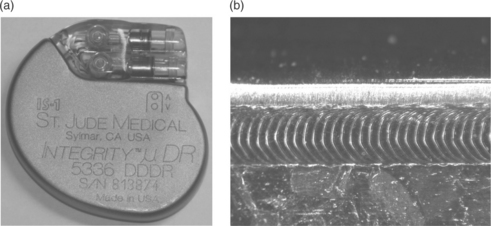
Figure 8.1 Hermetically welded pacemaker (Xie and Safarevich, 2003).
8.3 Laser conduction welding
Implantable medical devices are designed to be miniature and lightweight so that a thin metallic case is used for hermetic sealing. As a result, laser conduction welding mode instead of keyhole welding mode is more appropriate to achieve the shallow weld of the thin cases. Laser conduction welding mode is a process whereby a focused laser beam impinges upon the surface of the metallic substrate and the laser beam is partially absorbed by the metallic surface to melt the substrate by heat conduction and the rest the laser beam is reflected away by the surface (Fig. 8.2). A portion of absorbed laser energy is conducted away in the substrate as heat loss and a heat affected zone (HAZ) is formed adjacent to the molten pool. As a result, the weld depth is smaller than weld width in the conduction welding mode (Fig. 8.3a). The weld surface is smooth with no or little spattering after welding.
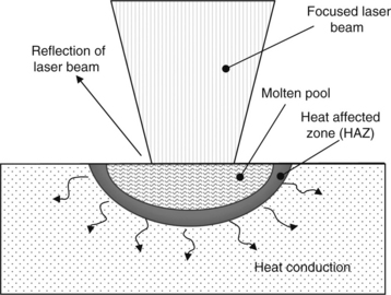
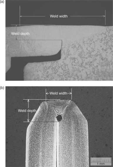
Figure 8.3 Cross-sections of laser welds by conduction and keyhole welding: (a) conduction weld; (b) keyhole weld.
Keyhole welding mode is a process in which the laser beam has a power density high enough to vaporize a substantial amount of material to create a ‘keyhole’ in the substrate (Xie, 1999, 2002). Nearly 100% laser beam is ‘absorbed’ or trapped by the keyhole due to multiple reflections along the side wall of the keyhole. In the keyhole welding mode, the weld depth is typically equal or greater than the weld width as shown in Fig. 8.3b. Spattering is often observed in the keyhole welding due to the violent movement of liquid in the keyhole and vaporizing of liquid metals (Xie, 1999). Keyhole welding mode is rarely used for implantable medical devices due to the possible collapse of the keyhole to cause a void at the bottom of the weld. The hermeticity of implantable medical devices is not guaranteed when a void is present in the laser weld (Fig. 8.3b). For a non-hermetic weld such as mechanical connection joints, both keyhole and conduction welding modes can be used depending on a specific joint design and joint requirements.
In laser conduction welding, the power density of Nd:YAG laser beams is typically in the order of 109 W/m2 or higher depending on materials to be welded. For the materials with high absorptivity and low thermal conductivity, such as titanium or stainless steel, it is relatively easy to achieve a keyhole welding mode at a certain power density than the materials with a low absorptivity (gold, platinum, etc.). Experimental analysis shows that the weld depth increases slowly with the power density in conduction welding mode but it sharply increases with power density once a keyhole is created.
8.3.1 Laser energy absorption
The absorption of laser energy by a specific material, or absorptivity, is an important parameter affecting the material melting in laser conduction welding. Only a portion of the incident laser energy is absorbed for welding and the rest of laser energy is reflected away by the substrate surface. The absorption is basically a process of laser-materials interactions and the process is usually called Fresnel Absorption (Xie et al., 1997). According to the classical theory of electrodynamics, the components of the electric field of lasers interact with the electric dipole moments of the metal atoms. The infrared absorption of metals mainly depends on conductive absorption by free electrons. The energy of these energetic electrons is transferred to the vibrating lattice by collisions which heat up the material. Therefore, the absorption of laser energy by metals largely depends on conductive absorption by free electrons and the absorptivity is a function of the electrical resistivity of the substrate (Xie et al., 1997).
The Hagen–Ruben relation, which defines the reflectivity of a solid surface in terms of the frequency of radiation of the conductivity of the solid, is used to determine the absorptivity (Xie et al., 1997).
where ρDC is the DC resistivity of metals in units of Ω-m and λ is the wavelength of laser beams in unit of µm. For Nd:YAG lasers with a wavelength of 1.06 µm, the absorptivity becomes:
In the case of CO2 lasers with a wavelength of 10.6 μm, the absorptivity is
![]() [8.3] Equation [8.3] is the equation same as that obtained by other researchers based on Fresnel absorption of CO2 lasers (Arata and Miyamota, 1972). It can be seen from Equations [8.2] and [8.3] that the absorptivity of Nd:YAG lasers is 3.16 times higher than that of CO2 lasers.
[8.3] Equation [8.3] is the equation same as that obtained by other researchers based on Fresnel absorption of CO2 lasers (Arata and Miyamota, 1972). It can be seen from Equations [8.2] and [8.3] that the absorptivity of Nd:YAG lasers is 3.16 times higher than that of CO2 lasers.
The absorptivity can be estimated for some metals using the above equations and given electric resistivity from the references (Touloukian et al., 1970; Iida and Guthrie 1988). The absorptivity for both CO2 and Nd:YAG lasers is calculated in Table 8.1. Note that the theoretical absorptivity is based on the assumption of pure polished metallic surface and no vapour plums above the substrate surface.
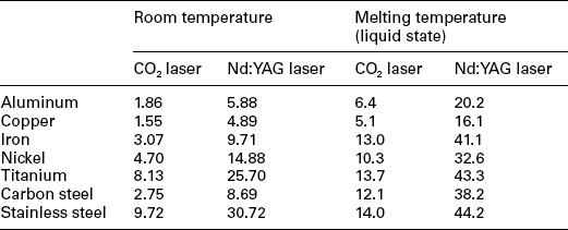
Titanium and its alloys are often used for implantable medical devices due to the features of biocompatibility, corrosion resistance, light weight, mechanical properties and manufacturability (formability and weldability). Compared with other metals, titanium has a higher absorptivity and is easy for laser welding at low laser energy. In laser conduction welding, it is expected that the absorptivity of titanium substrate is higher than the value in liquid state in Table 8.1 due to the high temperature of molten pool but the vapour or plasma plume above the titanium substrate may affect the absorption of the Nd:YAG laser beam as well. In general, titanium and its alloys have excellent laser weldability and good welds can be achieved without significantly technical hurdles for medical devices.
A surface oxide of metals can significantly increase the absorptivity of laser beams. An experiment showed that the absorptivity of cold rolled steel was almost doubled after exposed to an air furnace at 1000 °C for 40 s (Xie and Kar, 1999). Titanium is an active element and can be oxidized quickly when exposed to a temperature above 500 °C in air and the surface turns to be discoloured (blue, straw or purple). When titanium is exposed to air at the room temperature, a thin and shine oxide film is formed on the surface to protect the bulk titanium from further oxidizing. The thin oxide film formed at room temperature has no impact on the laser welding process.
It is noted from the Table 8.1 that copper has the lowest absorptivity and majority of laser energy is reflected away. This explains that copper is very difficult for Nd:YAG lasers to weld at the wavelength of 1.06 μm, but copper is a suitable material for laser welding fixture as the laser beam will not damage the fixture in case of misfiring and copper is also an excellent heat sink to protect the device from overheating.
8.3.2 Laser melting process
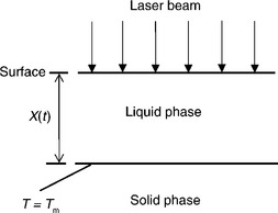
Once the laser beam irradiates on the surface of a substrate and is absorbed by the substrate, the surface temperature increases until melting to form a weld pool. The boundary of liquid and solid phases X(t) – melt depth during welding or weld depth after welding – keeps moving down until the laser is turned off. The laser melting process can be simplified as a one-dimensional heat conduction problem with the assumption that the diameter of the laser beam is large enough compared with the regions of interest as described in Fig. 8.4.
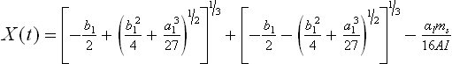
There are a number of mathematical models to predict the weld depth at various conditions and assumptions. The simplest expression of melt depth with an assumption of same thermal and physical properties in the solid and liquid phases is given by (Cohen and Epperson, 1968)
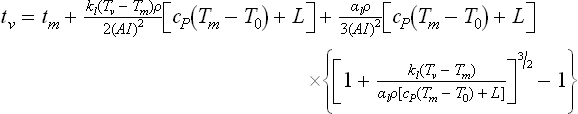
where X(t) is the melt depth, A is the absorptivity, I is the power density of laser beam, ρ is the density, L is the latent heat, t is the time from the start of the laser irradiation and tm is the time to start melting at the substrate surface. The melting time tm is given by (Cohen and Epperson, 1968)
Here α and k are thermal diffusivity and thermal conductivity while the subscript s and l represent solid and liquid phases, respectively. Tm is the melting temperature of substrate.
A more precise model was developed to consider the difference of thermal and physical properties in solid and liquid phases and the Stefan condition of latent heat transfer at the solid-liquid boundary (Xie and Kar, 1997) is considered. The governing equations and the boundary conditions in the model are given below
Here Ti, αi and ki are temperature, thermal diffusivity and thermal conductivity of the i-th phase respectively, where i = l and i = s represent the liquid and solid phase respectively. x is the distance from the surface of the workpiece, t is the irradiation time, Tm is the melting point, ρ is the density, L is the latent heat of fusion, T0 is the initial temperature.
The above-mentioned equations are a set of non-linear partial differential equations due to the non-linearity of the Stefan condition at the solid-liquid interface and an approximate solution was obtained for the one-dimensional phase-change heat conduction problem with time-dependent surface temperature involving laser irradiation (Xie and Kar, 1997). The approximate solution for the melt depth and melting velocity is found to be
Melting velocity:
where
The solutions for melt depth and melting velocity are quite complicated and difficult to use for a practical problem. It is found that the melt depth and average melting velocity can be further simplified when the power density of laser beams is greater than 109 W/m2:
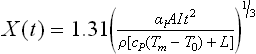
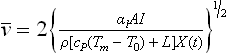
Equation [8.19] describes the dynamics of the melting process under laser irradiation and provides a relationship among the melt depth X(t), power density I and irradiation time t for various materials in laser conduction welding. At the beginning of laser irradiation, the melt depth increases rapidly with time and then increases slowly. It was reported that the theoretical results had a good agreement with experimental data for 304 stainless steel and copper alloy (Xie and Kar, 1997). The average melting velocity in Equation [8.20] increases as the power density increases and decreases as the melt depth increases, and such a trend has been observed in experimental studies as well.
It is also interesting to estimate the time to reach the melting and vaporizing temperature for various materials. Based on the mathematical model of laser melting described above (Xie and Kar, 1997), the melting and vaporizing time are obtained as follows:
Vaporizing time:
The melting and vaporizing time for Nd:YAG laser beams at two power densities are given in Table 8.2.
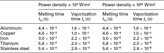
From Table 8.2, it can be seen that the times to reach melting and boiling temperatures at the substrate surface are found to be very short (about a few microseconds or less) at high-power densities. When reaching the boiling temperature, a vapour/plasma above the substrate may partially block the laser beam from reaching the substrate. Generally, the vapour or plasma in conduction welding is not as significant as keyhole welding, and the wavelength of Nd:YAG lasers is less sensitive to the blockage by the vapour/plasma plume than CO2 lasers which has a long wavelength of 10.6 μm.
8.4 Focused laser beams
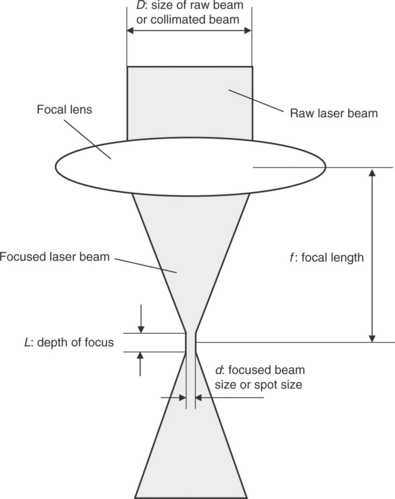
A laser beam is usually focused on the surface of a part to achieve the highest power density at the part. The power density of a focused laser beam or intensity, I, is defined as
where P is the peak power and A1 is the area of the focused laser beam (A1 = πd2/4). The size of the focused beam or spot size, d, is given by
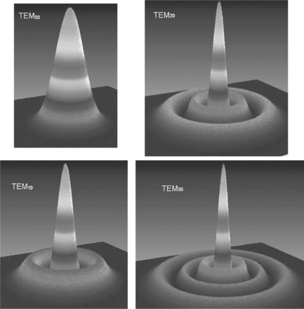
where λ is the wavelength, f is the focal length, D is the size of raw beam as shown in Fig. 8.5. M2 is a measure of beam quality that shows the power density distribution of a laser beam. A low value of M2 indicates good beam quality and ability to be focused to a small spot. When M2 is equal to 1, the power density distribution is in the form of perfect Gaussian distribution and it is described as TEM00 (TEM – transverse electromagnetic mode) as shown in Fig. 8.6. For circular laser beams with a TEMpq mode, the beam quality is M2 = (2p + q + 1)1/2. For example, the value of M2 is 2 for TEM11 and M2 = 1.73 for TEM10. According to Equation [8.24], the better the beam quality or lower value of M2, the smaller the spot size or the better in focus-ability. For flash-lamp-pumped Nd:YAG lasers, the value of M2 is large in a typical range of 20–200 depending on a number of factors including the laser emitting methods, laser power and optical systems. It has recently been reported that the beam quality (M2) of fibre Nd:YAG lasers is about 1.1, close to the Gaussian distribution (M2 = 1). A power-density distribution of a 4000-W Nd:YAG laser is shown in Fig. 8.7. It can be seen that the beam quality of the Nd:YAG laser is not Gaussian distributed and the power-density distribution is flat at top. However, the spot size is about 0.5 mm, which is still small enough for precise laser welding.

The question that needs to be answered is what impact does the beam quality have on the laser welding process, specifically on the hermetic welding of implantable medical devices. In general, a flat distribution of power density with a large value of M2 is preferred for conduction welding mode if the laser beam can be focused to a spot small enough. A low value of beam quality (M2) indicates a high-power density at the centre that might be easier to lead to keyhole welding mode at high energy. As mentioned in the previous section, keyhole welding mode is prone to weld voids due to instability of the keyhole and spattering during welding. For implantable medical devices, the large value of M2 or poor beam quality is acceptable, and actually a slightly larger spot size is helpful in covering the entire seam joint in case of offsetting the laser beam to the seam joint.
However, a large value of depth of focus is preferred. While the depth of focus does not affect the laser welding process, it does have an impact on the process robustness. In laser welding, a laser beam is typically focused on the part surface to achieve the maximum power density and the part surface must be kept within the range of depth of focus to keep consistent power density during welding. As a result, a large depth of focus is preferred in laser welding for improved process robustness. The depth of focus, L, is given by:
8.5 Laser welding parameters
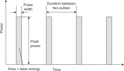
As discussed before, a pulsed Nd:YAG laser system is typically used to weld implantable medical devices to minimize the heat input during laser welding, instead of continuous wave (CW) lasers whose power output is constant over time. For example, if a pulsed laser welding process of a titanium part has welding parameters of pulse energy 2.0 Joules/pulse, pulse width 2 ms and pulse repetition 10 Hz, the average power of the laser welding process is equal to a lamp bulb at 20 Watts (2.0 J/pulse × 10 pulses/s = 20 Watts). In case of CW laser welding, the required laser power is in the order of one hundred watts to melt the titanium forming a weld. The low average power in pulsed laser welding is able to melt metallic parts due to the high peak power of 1 kW (2.0 J ÷ 2.0 ms = 1 kW).
The pulsed laser welding parameters to be developed for each application include:
• Laser energy, which determines the weld depth in laser conduction welding, is typically between 1 and 4 Joules for the hermetic welding of titanium/titanium alloy case.
• Pulse width (or pulse duration), which governs the power density at a certain energy, is typically within 1–8 ms for this kind of application.
• Pulse repetition (or pulse frequency) controls the overlap rate of two adjacent spot welds. The high pulse frequency achieves a high overlap rate.
• Travel speed controls the overlap rate as well. The low travel speed results in a high overlap rate.
The definition of laser pulses are shown in Fig. 8.8 and the relations among the parameters are described in Equations [8.26] to [8.28].
A pulsed laser seam weld is shown in Fig. 8.9. The overlap rate of adjacent spot welds is an important parameter to guarantee the hermeticity of a welded device. The overlap rate is typically greater than 70% for the purpose of hermetic welding. In many cases, the overlap rate is about 80% or higher. The overlap rate is defined as follows:
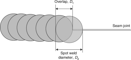
When laser seam welding is performed on a two-dimensional plane, it is relatively easy to achieve the consistent overlap rate over the entire seam weld by moving the device mounted on an X–Y table while the laser beam is kept stationary. In case of an irregular three-dimensional shape of an implantable medical device, special CAM (computer-aided manufacturing) software may be needed for the welding motion program in order to achieve the consistent overlap rate over the entire seam weld. The CAM software is able to create the coordinates of X, Y, Z and rotary axes and travel speed for each pulse weld based on the irregular three-dimensional shape of the device to guarantee the same overlap rate everywhere.
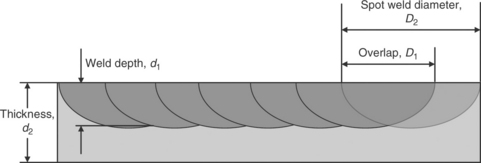
A full penetration weld is usually required for structural seam welds under a high mechanical stress and fatigue in service. However, implantable medical devices are not subject to a high mechanical stress so a partial penetration weld is acceptable as shown in Fig. 8.3a. The partial penetration of a seam weld is defined as
In Fig. 8.3a, the penetration is about 40%. The overlap rate can be estimated from the cross-section of seam weld in Fig. 8.10 as well.
8.6 Requirements for laser hermetic welds
Other than the requirement of weld depth and overlap rate, a ductile seam weld must be achieved for the implantable medical devices with titanium cases. Titanium and its alloys are the materials most often used for the case to hermitically seal the implantable medical device. However, titanium is an active element especially in the liquid state during welding. Titanium in liquid state can react with oxygen, nitrogen and hydrogen to cause a significant increase in brittleness and reduction in the ductility so inert gas such as argon and helium are used as shielding gas to protect the molten weld pool during welding. The source of oxygen and nitrogen are mainly from the air when improper shielding occurs during welding. A study showed that the hardness of commercial pure (CP) grade-2 titanium weld was increased from 242 to 373 Hv when 10% oxygen was added into the argon shielding gas (Li et al., 2005). In addition, the inert shielding gas is sealed inside the device for improved device reliability. As a result, a controlled environment with inert gases is typically used for laser hermetic welding while moisture, oxygen or nitrogen are controlled at a low level.
There is a microstructure change in titanium material after laser welding. It was reported that for CP grade-2 titanium the microstructure changed from an equiaxed alpha of relatively uniformed grain size (about 10–15 μm) to a mixed coarse-grained serrated alphas and a smaller amount of fine-grained acicular alpha, and the hardness changed from 191 to 242 Hv (Li et al., 2005). The change in microstructure is mainly due to the rapid heating and cooling in laser welding. The impact of the microstructure changes on reliability and performance of implantable medical devices is insignificant.
Although the titanium and its alloys have excellent weldability and good seam welds can be achieved in a controlled environment, there are a number of possible weld defects to affect the device hermeticity and reliability. The typical weld defects in the laser hermetic welding of implantable medical devices including the following:
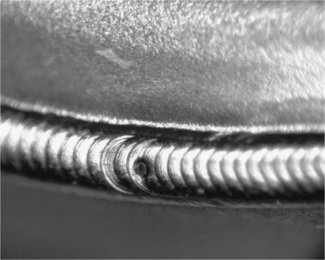
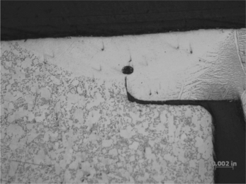
• Blow hole. A typical blow hole at the seam weld is shown in Fig. 8.11. This defect is caused by a bulk polymeric material sandwiched in the weld joint which is vaporized at the high temperature during welding. The gas venting from the bulk polymer causes a path in the liquid weld pool and the venting path becomes a blow hole on the seam weld after the solidification of the weld pool. The device with a blow hole will fail in the subsequent helium leak test to identify the hermeticity loss.
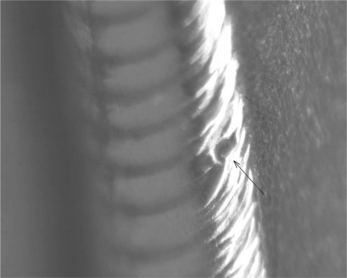
• Void in weld. When a tiny bulk polymer material is vaporized in the weld pool, the evaporation gas bubbles might be trapped in the weld pool forming a void (Fig. 8.12). The trapped voids are not visible from the weld surface and do not affect the hermeticity of the device, but the total weld depth is affected. The true weld depth should be the weld depth minus the diameter of the void if the void is right at the seam joint.
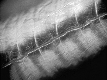
• Pinhole. The gas bubbles evaporated from the tiny bulk polymer might be just floating to the weld surface at the time of weld solidification. The surface voids are called pinholes as shown in Fig. 8.13. The pinholes do not affect the hermeticity in most cases but it might be a cosmetic issue.
• Cracking. The cracking on the seam weld mostly results from the metallurgical problems to make the titanium weld brittle (Fig. 8.14). Substantial foreign material or contamination are decomposed during welding and enter into the liquid weld pool to alter the metallurgy of titanium. The metallurgical alternation significantly increases the hardness and brittleness and potentially results in cracking to lose the hermeticity.
• Weld discolouration. The titanium seam weld is shiny silver if proper shielding is used. In case of discolouration on welds, such as yellow, purple or blue colours, it is an indication of oxide or nitride due to the contamination in shielding environment or poor shielding. The discoloured weld might be brittle with a high hardness and potentially lead to cracking on the seam weld. A slight discolouration might have a limited impact on the mechanical properties of weld metal (Li et al., 2005) and technically the weld might be acceptable for the implantation, but the non-conforming issue needs to address to meet GMP (Good Manufacturing Practice) requirements. Contamination in the weld joint may cause local weld discolouration as well.
A butt joint is typically used for laser hermetic welding of implantable medical devices. There are two issues that need to address in the joint design:
1. Potential damage of internal components by laser-beam irradiation from the gap between the case halves. A gap is always found between two case halves and it is possible for the laser beam to go through the gap to directly hit the internal components. As a result, a protective band underneath is needed (Fig. 8.15a) or the butt joint has a step to block the laser beam irradiation (Fig. 8.15b). The protective band can be spot welded to one side of the case half to align with another half when mating.

Figure 8.15 Butt joint design to protect internal components from laser damage: (a) butt joint with a protective band; (b) butt joint with a step.
2. Thermal damage by heat conduction during laser welding. Laser welding is a high-temperature process to melt the metal cases and there is a potential to thermally damage the internal components or reflow the adjacent soldering or brazing joints by heat conduction. The thermal damage by heat conduction is minimal with a proper joint design as laser welding is a localized heating process and the temperature dramatically decreases along the distance. The temperature at the bottom of the protective band was measured in laser welding of a thin titanium case and the temperature rising and cooling cycle is shown in Fig. 8.16. It can be seen that the peak temperature is about 538 °C and the duration at the high temperature is short. For example, the duration above 500 °C and 400 °C are 0.75 and 1.9 s, respectively. Therefore, the thermal damage from laser welding to the internal components is limited due to localized heating and small amount of heat input. If necessary, a protective layer around the internal components may be used.

8.6.1 Leak test of welded devices
All laser welded implantable medical devices must be subject to leak test in manufacturing to ensure the hermeticity. Military standard MIL-STD-883 Method 1014 (Seal) specifies the fine and gross leak-testing methods, and the most commonly used fine leak-testing method is the helium mass spectrometer. Helium gas is chosen for mass spectrometer leak testing due to the unique features of helium:
• Helium is present in trace amounts in the atmosphere (5 ppm).
• Helium has a high diffusivity due to the small size of molecules.
• Helium ions are easily separated from other ion species due to the significantly different mass-to-charge ratio.
Helium mass spectrometers are a well-established instrument with very high detection sensitivity and analytical capability. Gas molecules are vacuum pulled into the leak detector for ionizing by a hot filament and then separated into ion beams according to their mass-to-charge ratio. The helium ion beam is tuned so that only the helium ion beam is allowed to strike the ion collector to produce an ion current. Then the ion current is amplified to display as a helium leak rate.
Residual gas analysis (RGA) is often used to verify the hermeticity of implantable medical devices, especially after implantation in human body for a certain period of time. RGA is a quantitative method to analyse the internal gas compositions of a hermetically sealed device. The RGA results can be used to compare to the original gases sealed in the device to understand the hermeticity loss.
RGA is performed by piercing the sealed device to release the internal gases from the device to a mass spectrometer. MIL-STD-883 Method 1018 (Internal Gas Analysis) specifies the calibration requirement, sample preparation and testing procedures. All of gases greater than 0.01% by volume shall be reported and typically the gases to be reported include N2, Ar, He, O2, CO2, CH4, NH3, H2 and water (H2O). In addition to the moisture content we concern most other gas compositions such as oxygen or nitrogen, if any, from RGA testing may provide additional information on hermetic-sealing process issues.
In laser hermetic welding of implantable medical devices, a controlled inert gas environment to prevent liquid metal from oxidizing during welding is used and then the inert gases are simultaneously sealed in the device. The inert gases can be argon, helium or mixture of argon/helium, but helium should be used for the subsequent helium leak test. A mixture of argon and helium is often used for economic reasons since helium is more expensive than argon. In case of RGA results to show the significant change in gas compositions when compared to original gases sealed in manufacturing, it suggests that this device may loss the hermeticity or issues to seal wrong gases during manufacturing.
8.7 Conclusion and future trends
Pulsed Nd:YAG laser welding is a hermetic-sealing technique often used for implantable medical devices to protect the microelectronic circuits inside. Pulsed Nd:YAG laser welding is a stable, precision and non-contact process offering a number of benefits such as reliably hermetic sealing, low heat input, localized heating, minimum weld distortion and ease of automation, and has been successfully used for high-volume manufacturing of implantable medical devices. A high yield in manufacturing depends on a number of factors such as proper joint designs, materials selection, development of process parameters and process control. In this chapter, the theory of laser conduction welding, including absorption of laser energy and laser melting process, fundamentals of laser beams and optics, critical process parameters, typical weld defects and root causes, has been discussed to help better understand the laser welding process for implantable medical devices. It is hoped that that the contents of this chapter can help the medical-device industry develop a proper laser welding process to achieve the highest quality of implantable medical devices.
There is a strong desire from patients to use smaller implantable medical devices so that thinner and small metallic cases have to be used to hermetically seal the device. In the application of implantable sensors, a thin metal diaphragm (equal or less than 25 μm) is needed to hermetically weld to a device with no distortion, no weld defects, good fatigue strength and good yield. These are the challenges to the laser hermetic welding technique and a number of issues need to be addressed to achieve a high-quality and highly reliable seam joint, for example,
• The joint design is critical to weld the parts together with a significant difference in thickness. The successful joint design needs to consider the heat balance during welding, release of weld residual stress, weldability of materials combination, laser-material interaction and visual detectability of weld defects.
• Proper tack weld techniques (laser welding, projection welding or solid-state welding, etc.) to minimize the distortion or the welding sequence to minimize the residual stress.
• Proper process parameters for a robust process in volume production and minimum distortion such as low heat input and small laser beam.
• Good inert gas shielding to the weld pool in a controlled environment.
The development of laser techniques in recent years might be helpful in overcoming the challenges. There are a number of new lasers that can potentially be used for welding applications, including short wavelength lasers (green laser at the wavelength of 532 nm or UV lasers at 355 nm), while the fundamental Nd:YAG lasers have a wavelength of 1064 nm, high-power diode lasers, disk lasers and fibre lasers. The short wavelength lasers are able to improve laser absorptivity and are good for some high reflective materials (gold, platinum, copper, etc.). Fibre lasers have great potential for use in hermetic welding of implantable medical devices. The fibre laser beam has a high beam quality close to Gaussian distribution (TEM00) due to the length of fibre cavity to eliminate thermal distortion of optical path and therefore the fibre laser beam can be focused to a very small spot. It has been reported that the spot size of the focused laser beam could be as small as 15 μm and can be used for small device welding coupled with a precision fixture. Other than the small beam size, the fibre lasers offer excellent beam stability, short pulse and minimized heat affected zone (HAZ). In addition, unlike a conventional laser in which the laser cavity is constructed from components such as mirrors, rods and lenses, the laser cavity in fibre lasers is constructed monolithically by the doped active fibre with several meter-long and fibre Bragg gratings replacing conventional dielectric mirrors to provide optical feedback. An immediate advantage of this is that there is no need for alignment, adjustment or subsequent cleaning of optical surfaces once the laser has been built, which means little or no maintenance requirement.
8.8 References
Arata, Y., Miyamota, I. Some fundamental properties of high power laser beam as a heat source (Report 2): CO2 laser absorption characteristics of metal. Trans. Japan Weld. Soc.. 1972; 3:152–162.
Cohen, M.E., Epperson, J.P. Electron beam and laser beam technology. Adv. Electron. 1968; 4:139–186.
Iida, T., Guthrie, R.I.The Physical Properties of Liquid Metals. Oxford: Clarendon, 1988.
Li, X., Xie, J., Zhou, Y. Effects of oxygen contamination in the argon shielding gas in laser welding of commercially pure titanium thin sheets. J. Mater. Sci.. 2005; 40:3437–3443.
Liu, X., Demosthenous, A., Donaldson, N. Implantable stimulator failures: Causes, outcomes, and solutions. Proceedings of the 29th Annual International Conference of the IEEE EMBS, Lyon, France, 2007:5786–5789.
Touloukian, Y.S., Powell, R.W., Ho, C.Y., Klemens, P.G.Thermophysical Properties of High Temperature Solid Materials. New York: Macmillan, 1970. [Vol. 1, 3 and 10].
Xie, J. Plasma fluctuation and keyhole instability in laser welding. International Conference on Applications of Laser and Electro-Optics (ICALEO ’99). Laser Institute of America, 1999.:D11–D20.
Xie, J. Dual beam laser welding. Weld. J.. 2002; 81:223s–230s.
Xie, J., Kar, A. Mathematical modeling of melting during laser materials processing. J. Appl. Phys.. 1997; 81:3015–3022.
Xie, J., Kar, A. Laser welding of thin steel sheet with surface oxidation. Weld. J.. 1999; 78:343s–348s.
Xie, J., Kar, A., Rothenflue, J., Latham, W. Temperature-dependent absorptivity and cutting capability of CO2, Nd:YAG and chemical oxygen-iodine lasers. J. Laser Appl.. 1997; 9:77–85.
Xie, J., Safarevich, S. Laser materials processing for medical devices. Proceedings of ASM Materials & Processes for Medical Devices, Anaheim, California, USA, 2003:25–30.