
Validating hermeticity in welded metallic implantable medical devices
Abstract:
The term hermetic seal has various meanings to many in the medical industry. All enclosures will leak, just at different rates. The process and design goal is to manage this leak rate to ensure the package remains safe and effective for the patient or users throughout its design life. The word hermetic is taken from the name of the Ancient Greek alchemist Hermes Trismegistus who is claimed to have invented a magic seal to make vessels airtight. This chapter will highlight several aspects of hermetic seals, and will present the first principles of this process, to enable all practitioners to discover Hermes’ ‘magic’ seal.
9.1 Introduction
Hermetic sealing is a key step in maintaining long-term performance of many medical devices. While electrical and mechanical designs can work safely and effectively in the laboratory or manufacturing environment, devices can and will fail when implanted if not properly sealed to prevent ingress of biological material or to prevent loss of internal gases. Failure can also occur prior to implant during shipping and handling, and exposure to harsh environmental conditions prior to the final-use conditions.
Early electronic enclosures were hermetically sealed to prevent ingress of moisture. This moisture content could excite and promote localized corrosion cells, which degrade metallic circuits and eventually cause total circuit failure.1,2 Current devices such as implantable defibrillators generate very high voltages, and require specialized gases within the enclosure to maintain arc suppression. Loss of these critical gases will allow arcing and also lead to damage of critical circuits.3
While a good hermetic seal is vital to the overall performance of the device, cleanliness of the components plays a major role. This is especially true for devices that are low-voltage impedance matched, or microwave units that require low losses. High ionic contaminants in these assemblies can lead to corrosion, dendritic growth or whiskers, leading to short circuits or poor electrical performance.4
The term hermetic seal has various meanings to many in the medical industry. All enclosures will leak, just at different rates. The process and design goal is to manage this leak rate to ensure the package remains safe and effective for the patient or users throughout its design life. Webster’s dictionary cites the definition of ‘hermetic’ as: ‘Completely sealed; especially, sealed against the escape or entry of air’. The word hermetic is taken from the Ancient Greek alchemist Hermes Trismegistus who is claimed to have invented a magic seal to make vessels airtight. The following sections of this chapter will highlight several aspects of hermetic seals, and will present the first principles of this process, to allow all practitioners to discover Hermes’ ‘magic’ seal.
9.2 The physics of leak rates
The initial need for hermeticity was to ensure the electronics or mechanical assembly remained in an effective moisture environment. Ingress of moisture from the body or from outside air can lead to corrosion cells on the circuitry.
Ingress of moisture to an enclosure raises the internal moisture content to the point that condensation can occur. While this is not a key issue for human implantable devices, which will assume a stable body temperature, the transit, storage and shipping of devices can often expose the units to condensation temperatures. The electronics industry has focused on keeping moisture contents below 5000 ppm for most hermetic devices. This requirement is driven by simple atmospheric physics as shown in the moisture vs dew point temperature plot of Fig. 9.1. In this plot it can be determined that for moisture levels of 6000 ppm, the dew point temperature is the freezing point of water, 0 °C (32 F). This means that, at 6000 ppm internal moisture, condensation as water droplets will form on the internal circuits at low temperatures. If ionic contaminates are present, the condensed moisture can solvate and activate these contaminants forming ionic compounds that under applied voltages and current act as a plating cell. The resulting oxidation-reduction reactions form corrosion products that degrade the metallic conductors. This degradation will eventually lead to open or short circuits and limit the device lifetime. Often the device electrical performance fails specification long before catastrophic conductor damage occurs.5,6 For these reasons, early electronic systems for military applications were designed to a limit of 5000 ppm moisture so that the dew point was below freezing.7
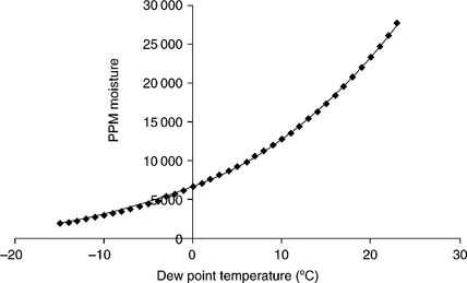
Figure 9.1 Plot of internal moisture content vs dew point temperature. This graph should be used to ensure the full range of environmental temperature exposure does not allow liquid droplets (condensate) to form on internal surfaces.
Current devices often use other techniques to maintain proper moisture content. These techniques incorporate moisture ‘getters’ in the form of silica gel packets, coatings, or hydrophilic plastic inserts to preferentially absorb moisture and prevent high levels of moisture even if a seal is compromised. Some commonly used desiccants for electronic devices are shown in Table 9.1.8,9
Table 9.1
Commonly used desiccants and getters for internal moisture controls
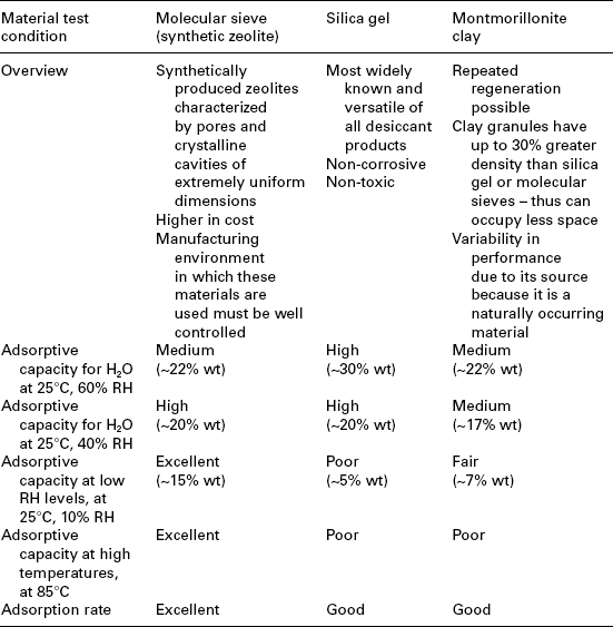
Source: Courtesy of Guidant – Boston Scientific.
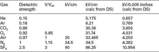
The second key requirement for hermetic seals is to maintain the designed gas environment within the sealed system. This requirement typically pertains to the need for electrical arc suppression within devices that are designed for high voltages (>250 V) or high currents (>50 mA). Common gases for these types of circuits include nitrogen, argon, helium and sulfur hexafluoride. The arc-suppression capability of these gases is shown in Table 9.2 for a range of gaps. The gap width is critical in maintaining or extinguishing an electrical arc. Along with the gap, is the shape of the conductor carrying the voltage also has a strong effect on maintaining or promoting arcs. Much work has been done to study these arc processes, generally using a spark-gap system where a fixed pointed electrode is offset from a flat plate. The environmental gases are imposed at the gap and voltage is applied until an arc jumps the gap. The ability of the arc to jump the gap is a strong function of the gap distance, the ‘sharpness’ of the electrode point, the applied voltage and ionization characteristics of the gases in the gap. Ingress of moisture and oxygen will poison the gas mix and degrade the ability of the system to maintain arc suppression.10
9.2.1 Leak paths
When testing devices for leak rate, the final measurement is the sum of all leaking paths. Sometimes these are easy to detect and are ‘gross’ defects, and others are extremely difficult to detect and may in fact change over time. Regardless of the rate of leak, some general physical principles apply to all leaks:
• Diffusion and flow of gases will occur to normalize concentrations.
• Diffusion and flow of gases will occur from the high concentration into the lower concentration.
• Leaks will follow the pressure differential from high to low.
• Measured leak rates are the sum of all active leak paths.
• Many leak paths will become blocked or sealed by contaminants, oils, corrosion products, or liquids.
• Gases and vapours will leak faster than liquids.
• Gases and vapours will leak through smaller features than liquids.
• Leak rates generally show logarithmic decay, but over short time spans can be modelled with linear equations.
• Straight leak paths will have higher leak rates than tortuous leak paths of equal length.
Leak paths allow gases or vapour to escape from an enclosure.11 While the internal gases escape, external gases are allowed in and contaminate the environment. To understand the flow rate through these small orifices and cracks, we must understand the flow properties of gases under various conditions.
From vacuum technology we know that gases flow under conditions of molecular or viscous flow.12 Molecular flow is typical of vacuum conditions below 4 mT, and is driven by the collision of molecules with the walls of the tube or crack through which it flows. Since most medical devices are sealed at room pressure or slightly positive pressure, the gas concentration within the device is very high (relative to vacuum) and the molecules mean-free-path distances are very short. This means the molecules interact and collide with each other far more frequently than the walls of the tube or crack they are flowing through. Therefore, the characteristic gas viscosity best describes the gas-flow properties within a device and for leaks above 10−5 He atm/cc.
Many leak testers impose a vacuum differential on the device under test. In this manner the pressure outside the device is lowered to enhance the flow of gas out of the device and into the test unit. In these cases, the flow of gas from the device can be molecular flow. In molecular flow, there are so few gas molecules that the mean-free path between molecules is large in comparison with the crack or tube they are flowing through. In this case the gas has a higher probability of interacting with the walls of the crack or tube than with a fellow gas molecule. This type of flow cannot be characterized by viscosity, as there are no longer any shear forces acting on the gas molecules as they flow past each other. This gas flow situation occurs at low pressures (<10 mTorr) and low leak rates, typically 10−7 He atm/cc or better.
These flow regimes are described in vacuum technology as turbulent flow (high Reynolds number), viscous flow (medium Reynolds number) and molecular flow (low Knudsen number). The transition between flow regimes is best estimated by use of the Reynolds and Knudsen numbers.13 Table 9.3 lists the approximate range of the Reynolds and Knudsen numbers that describe the transitions between flow regimes. The relative numbers are derived in the next section.
Table 9.3
Dimensionless Reynolds and Knudsen numbers
| Flow type | Typical Reynolds numbers | Typical Knudsen numbers |
| Turbulent | >2300 | – |
| Viscous | <1200 | <0.01 |
| Molecular flow | – | >1.00 |
Reynolds number is defined as:
where:
Similarly, the Knudsen number is defined as the ratio of the molecular mean-free path L to the radius of the crack or tube:
And the mean free path is defined as:
The rate of flow of gas through a crack or small diameter tube is given by:
where:
The overall throughput Q is dependent on the overall resistance to flow across the length of the tube or crack. For most leaks, there is a strong pressure differential from the inside or beginning of the crack or tube, to the end of the crack or tube and the outside environment. The throughput Q can then be written as a function of:
or as:
where:
Pex = the pressure at the exit point of the leak
It is worth noting that Equations [9.5] and [9.6] are analogous to Ohm’s Law, which relates the flow of electrical current (I) through a resistance (R)under the influence of a potential difference (Volts).
So in a similar manner to electrical circuits, the resistance to gas flow is found to be the sum of the resistances in the system, given as:
where Ztotal is the total resistance to gas flow and the contributing factors include the resistances of changes in direction (tortuosity), diameter, coatings, contaminants, partial blockages and the like.
These basic elements of gaseous flow form the key background to work completed by French scientist Poiseuille. In his work on gases, he derived the following equation that describes the viscous flow of gases through a straight tube of small cross section. This equation generally holds for pressures above 10−3 torr, where gas viscosity is still a dominant feature of the flow. Below this pressure, viscosity no longer describes the molecular motion.
The Poiseuille equation is given as:
where:
Combining this equation with the conductance Equation [9.3] we yield the most used form of the Poiseuille equation:
From Equation [9.10] we see that the conductance (typical units L/s) is a strong function of the tube diameter. Therefore, as the effective crack diameter or cross-section decreases, the ability to maintain a leak path of significant flow diminishes rapidly. A plot of conductance versus crack/tube diameter is given in Fig. 9.2.
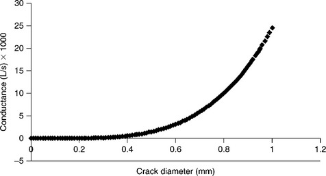
Figure 9.2 Plot of air conductance (L/s) vs tube diameter ‘d’ and a fixed crack length of 1 mm and viscosity of 1 poise at 1 atm differential.
Other key insights from Equation [9.10] relate to the gas property of viscosity and the overall crack length. As the gas viscosity increases and or the crack-length path increases, the leak-flow rate decreases.
The Poiseuelle equation can be used to optimize the seal design. The best design will not allow for a straight-through crack but instead will change direction. Seam or joint designs that meet this requirement will be discussed later in this section. Further, any potential leak path should be made very long relative to the crack diameter. Finally, the choice of sealing gas, while not always a process choice, should be as high a viscosity as possible and of highest molecular weight possible to reduce the potential for flow.
9.2.2 Joint designs for hermetic sealing of electronic enclosures
Previous chapters of this book will have discussed material selections for medical devices and reviewed the welding and joining requirements for those materials. This section will review some selected joint or seam designs in current medical devices that yield hermetic seals with very low leak rates.14
Figure 9.3 shows several typical joint designs. A simple overlap seam weld with a full or partial penetration weld or braze is sufficient to form an excellent hermetic seam. Penetration into the parent materials across the seam is required, but full penetration of the parent materials is not. The important feature of a hermetic seam is the area joined at the interface of the two mating surfaces, not the penetration in the second or most inner material. In fact, it can be shown that over-penetration leads to severe defects, increased stresses and a higher potential for cracks.
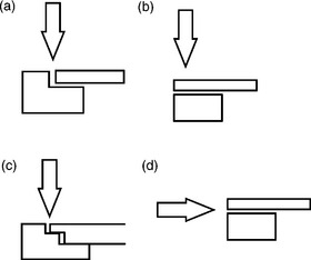
Figure 9.3 Typical joint designs for hermetic seals in medical devices. (a) Lap seam weld; (b) through thickness lap weld; (c) stepped lap seam weld; (d) off axis lap weld.
Two key aspects must be maintained for high process yields for hermeticity. These requirements include:
• good fixturing that controls the fit-up during the welding and joining process;
• proper penetration or wetting of the seal area;
• proper or optimized overlap of pulsed weld zones;
• proper material choice to avoid cracking or delamination in the seal area.
A key similarity in many medical devices is the need for a small thin-walled can or container to hold the necessary electronics, power supply, batteries, capacitors and other circuit functions. This package must be hermetic to at least moisture ingress, but is typically gas tight to even low volumes of helium. Typical housings in medical are MP35N, 316L, or the most common, commercially pure titanium. Hermeticity is required to ensure moisture attack cannot cause corrosion and eventual shorts or opens of the circuits. Note that many hermetic enclosures in use today also incorporate getters for oxygen and moisture, to improve long-term reliability and quality. Regardless of the sealing technique, a minimum of 50% spot-to-spot overlap is recommended, with 75–80% overlap common practice. Also, note that the important aspect is to achieve overlap of the weld zones at the interface of the joint. Over-penetration of individual spots is detrimental and penetration does not correlate to hermeticity; it is the continuity of the seal at the interface. This is shown schematically in Fig. 9.4.
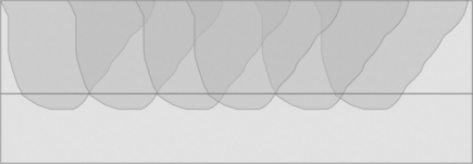
Figure 9.4 Schematic diagram of overlap pulse requirement and penetration in an overlap weld design. Note it is the weld area at the interface that drives hermeticity, not penetration into the innermost layer.
Three processes have been widely used to hermetically seal thin-walled medical cans:
Resistance welding is an excellent choice when the can materials are resistive as in the case of MP35N or 316L stainless steel. Opposed electrodes are clamped against a flange of the housing and slowly rotated to traverse the length of the package. Current and voltage is applied to form overlapping resistance weld spots. After the first pass along two parallel sides, the electrodes retract, the part rotates 90 ° and the process is repeated along the two remaining sides. Circular packages can also be sealed with this technique. Disadvantages of the process are the requirements for a flanged cover, which is often nickel and gold plated. In this manner the resistance weld is actually a resistance braze, forming a eutectic alloy of gold–nickel at the interface. This allows the process to run somewhat faster and use less heat input than full fusion welding of the higher melting point MP35N or 316l stainless steel.
Plasma welding has hermetically sealed more medical pressure bellows than any other process. Pressure bellows are formed from a stack of preformed thin metal discs, sealed along their periphery. In a manner similar to arc processes for sealing wire tips, the arc is drawn to the sharp edge of the disc, melting and sealing the disc edge. The process produces a weld seam very similar to pulsed laser welding, but with slightly increased heat input. It is an excellent process for sealing flanged enclosures as well. Its disadvantage is the heat input for deeper penetration welds, as well as the close proximity of the torch face to the weld zone itself.
Laser welding is today the most popular and easy to implement for hermetic sealing. Advantages are the ease of ‘point-and-shoot’ line-of-sight welding capability, and the ease with which automation can track odd package shapes and configurations. Deeper penetration welds can be developed without overheating critical glass or ceramic feed-throughs, and weld cycle time is the shortest for laser welding. Disadvantages are often the initial start-up capital cost, training and laser-safety requirements, and the need for excellent part fit-up. A general rule of good laser welds is the joint fit-up must have a maximum joint gap of 10% of the thinner material. Excessive gaps cause the laser to punch through one layer causing a hole, or the edges of the seam pull back due to the molten material surface tension. An example of a seam weld with too much gap is shown in Fig. 9.5. Note the smooth-balled edges on each side of the seam. An example of a well-formed hermetic seam weld is shown for a pacemaker pulse generator in Fig. 9.6.
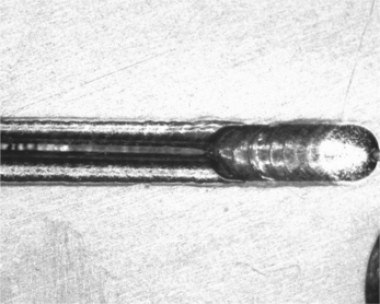
Figure 9.5 Example of a poor hermetic seam due to poor joint fit-up. At the start of the weld the gap was too large and pull-back occurred. As the gap decreased, the weld melt was able to bridge the gap and begin to form a seam. When the gap exceeds approximately 10% of the thinner material, the surface tension forms a ball on the edge of the joint, negating flow across the joint. (Photo courtesy of Edison Welding Institute.)
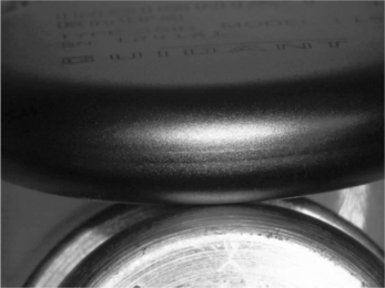
Figure 9.6 Example of a well-formed and polished hermetic seam in the titanium shell of a heart pacemaker. (Photo courtesy of Guidant Corporation.)
A key item to note is that fixturing of the device and the material cleanliness will define the process yield. The fixturing and the welding process must control and optimize the heat input so that warping or expansion of the joint gap does not occur. When the fixturing is insufficient or the thermal inputs too high, the weld seam pushes ahead a bow-wave of thermal energy. This excess heat causes expansion of the weld joint that can lead to defects in the weld seam. This is typically seen to occur at some mid-point in the weld seam, where the process starts properly but then loses the weld seam thereafter.
Another key defect is due to poor cleanliness. Most welding processes have a very high-energy density, which can cause vaporization of most organic contaminants. These contaminants will boil rapidly and flash off, leaving cracks, craters and other defects that lead to high leak rates.
Cleanliness of the weld zone is also a strong function of the gases used during the sealing process. Argon, nitrogen, helium, and hydrogen are often used in combination to promote a smooth shiny weld zone that does not entrap gases or contaminates, or cause sooting. A laminar flow of low-pressure gas is recommended over the weld zone to control ingress of oxygen and to promote good thermal control of the weld pool. The effects of cover gas can be seen in Figs 9.7 and 9.8. In these examples, the stainless-steel plates were conduction welded with a low-power laser to yield a partial penetration weld seam. The degree of spatter, surface cleanliness, and overall penetration are affected by the choice and presentation of cover gas.
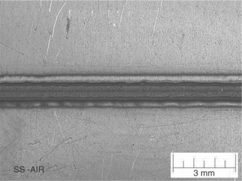
Figure 9.7 304 SS plate with partial penetration welds without cover gas. Note the surface oxidation and spread of the heat affected zone. (Photo courtesy of Edison Welding Institute.)
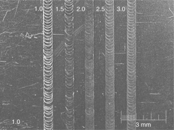
Figure 9.8 304 SS plate with partial penetration welds with helium–argon cover gas. Note the reduced surface oxidation and minimal spread of the heat affected zone. The numbers are the laser pulse width at constant power for all welds shown. (Photo courtesy of Edison Welding Institute.)
A second element of the gas choice during sealing is to use one of the gases for leak detection post-welding. Most medical-device manufacturers use a mix of argon-helium during the welding process. This choice allows a helium-leak-check system to be used post-welding to determine the leak rate of helium gas exiting the device through any cracks, crevices, or other defects in the enclosure.15,16
9.3 Measurement of leak rates – testing and verification
There are a wide variety of methods and techniques to determine the quality of a hermetic seal. Each technique has limitations on the level of defect that can be reliably detected. Helium mass spectrometry is an excellent method on which to compare the various techniques. Where possible the approximate helium-leak rate for each method is given. The key techniques in use today include the following:
• Bubble test (10−4–10−5 He atm/cc),
• Weight loss (10−1–10−3 He atm/cc),
• Radioactive tracer gas (10−7–10−9 He atm/cc),
• Helium mass spectrometer (10−5–10−9 He atm/cc),
Each of these will be described in further detail below.
9.3.1 Bubble test
Leak testing by detection of bubbles is likely the easiest and most common method. The typical approach is to fully submerge the sealed device in a small tank of fluid, and simple visual inspection or magnifying glass is used to inspect for a stream of bubbles emanating from the seal. The tank of fluid is often water, but low viscosity silicone oil, fluorinert, or solvents such as hexane or alcohol are also used. The tank of fluid is often heated to some degree, which serves to expand the gases enclosed in the device and provide an adequate pressure differential to drive the leak out of the package. A magnifying glass is very helpful, as is a vibration-free location, as the bubble stream can be very small. The advantage of this approach is its very low cost of implementation and its detection of the exact leak location. Once located, some defects can be re-sealed or re-welded to repair the leaking zone. A disadvantage is the limit of the leak-detection capability. The bubble test will typically correlate to helium-leak rates near 10−4 or 10−5 He atm/s.
9.3.2 Weight loss
A simple weight loss can also be used for some devices. Liquid-filled devices or devices filled with heavy gases such as tetrafluoroethane (134a refrigerant gas) can easily detect some leaks by simple weight loss. In this technique a laboratory analytical scale is used to weigh the device. A typical process is to equilibrate the sample for 24 h at room temperature and then record the initial weight to an accuracy of 0.1 mg. The device is then left in the equilibration chamber for 72 h and the second weight is then recorded. The weight loss is then calculated and scaled to a loss rate in units of mg/day or mg/year. The longer the time delay between measurements the more accurate the test. This test, like bubble testing, is easy to implement and very low cost. However, the method is not very specific, does not delineate the location of the leak, and lacks sensitivity. It is also an off-line test and not easily amenable to full-scale production.
9.3.3 Radioactive tracer gas
Radioactive tracer gas is an early method used in many OEM electronic packages developed for defence and space applications. The technique imposes a mixture of krypton-85 and dry nitrogen gas onto a package. A ‘bomb’ is used for this purpose, which is a simple closed system similar to a pressurized paint can. The sealed devices are bombed with the gas mixture at a slight overpressure to force the gas mixture into the device via any cracks or pores. The devices are then removed, passed through an air knife to remove residual gases adhered to the exterior surfaces, and then placed into a Geiger counter (scintillation detector). The Geiger counter detects the number of Kr-85 particles forced into the device. A calculation is then made based on a fixed equation that uses the concentration of the Kr-85 gas, the mix ratio of nitrogen, the bomb pressure and the exposure time. This technique is included here for completeness, but has fallen from common use due to the radioactive tracer gas. Current laws have curtailed the availability and ease of use of the Kr-85 gas, and significant safety and environmental controls are now necessary to incorporate its use.
9.3.4 Helium mass spectrometer
The helium mass spectrometer has been the most used method in the medical-device industry. The systems, while complex in theory and somewhat expensive, are safe, reliable, and capable of detecting the smallest leaks. Current units are fast, simple to calibrate, and are used in off-line, at-line and in-line techniques to support full production testing.
In this method helium gas is detected as it flows out of the sealed device. The device is expected to have some volume or concentration of helium gas. The device is placed in a controlled volume chamber and pumped down to hard vacuum. The pressure differential causes helium atoms to flow out of cracks, crevices, and pores and is detected by the tuned mass spectrometer. The technique is very sensitive as it counts the actual molecules of helium and calculates the leak rate. Typical leak rates for well sealed medical devices such as pacemakers and defibrillators are 1 × 10⁻⁸ He atm/s.
As indicated above a concentration of helium is required in the package. Early techniques of leak detection ‘bombed’ the package to force helium gas inside the enclosure. Helium has the advantage of the next-to-smallest atomic size (only hydrogen is smaller), is inert, and is a favored cover gas for laser and arc welding. Early practices often sealed the device in open air or nitrogen, so that little helium volume or concentration was inside the package during sealing. Helium was then forced into the package by bombing for minutes to hours in a pressurized can with pure helium. Current practice completes the welding and joining operation in a controlled atmosphere including a controlled volume of helium, 1–10% by volume is typical. By welding in the helium concentration, direct measurement of the helium by mass spectrometry can occur.
9.4 Determining leak rate based on helium content
The concept of leak detection by helium mass spectrometry grew out of the defence electronics era via the methods described in MIL-STD-883, test method 1014 for seal integrity. The approach was studied and developed at the Rome Air Development Center (RADC) in the 1960s.4,7 The concepts and methods of this standard are still used today as the baseline approach for bubble, radioactive tracer, optical stress, dye penetrant and helium test conditions.
As stated in an earlier section, the key reason for hermetic sealing is to avoid ingress of moisture and subsequent corrosion and failure of the electronic circuits. To keep the internal moisture content below that needed for condensation, the moisture content must be maintained below 5000 ppm. In work completed to meet this requirement, researches at RADC determined air-leak rates for various size packages to maintain this moisture content over the device lifetime. The baseline criteria for air-leak rates by volume are given in Table 9.4.
Table 9.4
Package volumes and specification air leak rates to maintain 5000 ppm moisture limit
| Volume | Allowed air leak rate |
| 0.1 cm3 or less | 5 × 10⁻⁸ atm cm3/s |
| 0.1–0.4 cm3 | 1 × 10⁻⁷ atm cm3/s |
| 0.4 cm3 or greater | 1 × 10⁻⁶ atm cm3/s |
The limit provided for electronic devices is an air-leak rate of 1 × 10⁻⁶ atm. cc/s air for internal free space volumes greater than 0.4 cc. Most implantable medical devices will use this baseline specification for an air-leak rate to maintain proper seal integrity and to scale the different measurement techniques.
The table of air-leak rates forms the basis on which to scale the measurements of the helium-leak test. The method uses the well-known Howell-Mann equation that relates the air-leak-rate specification for the given volume to the required helium-leak rate measured by mass spectrometry. This scaling equation is necessary for two reasons. First, helium has a far different diffusion rate and atomic size. Helium is therefore able to leak at a far higher rate than air through the same crack or pore. Second, the leak rate is not linear and has an expected exponential decay. This exponential rate affects two processes in the leak-rate method, getting the helium into the sealed package by bomb pressurization, and extracting the helium out of the sealed package by vacuum pressure differential. The Howell-Mann equation was built around the concept of pressure bombing the part to be tested. The bomb was a sealed pressure vessel where the sealed device was over pressured with 40 psi helium for minutes to hours, to force some volume of helium inside the package. The volume or concentration of helium in the package will affect the leak-rate measurement and must be accounted for in the equation. The concentration of helium in the package is an important variable. In the extreme case of a gross leaker where all the helium has leaked out prior to mass spectrometer testing, the test system will pump down and yield a very low leak rate, but obviously a false test. The variables used in the Howell-Mann equation are given below.
9.4.1 Variable definitions
| R1 = helium-leak rate | – scaled leak rate of helium using L |
| Decay = decay in leak rate | – exponential decay in leak rate based on hold time T2 |
| L = 1 × 10⁻⁶ atm.cc/s air | – standard leak rate related to package volume |
| Ma = 28.7 | – molecular weight of air |
| MHe = 4 | – molecular weight of helium |
| Content = 0.95/100 | – percent helium in device at time 0 (example = 0.95%) |
| Pe = 760 × content torr | – partial pressure of He in device |
| P0 = 760 torr | – standard atmospheric pressure |
| T2 = 2 × 3600 s | – maximum 2 h exposure in ambient air prior to leak test |
| V = 1.5 cc | – minimum internal free space volume (example 1.5 cm3) |
9.4.2 Using the Howell–Mann rate calculations
It is generally desirable to split the equation into two parts. In the initial use of the equation the typical operation used a pressure bomb to force the leak test gas into the already sealed device. The second part of the equation measured the amount of the gas that leaked out during the hold period. In most current instances, there is already an imposed volume of tracer gas captured in the device during welding and sealing.
In the case of many implantable defibrillators and pacemakers, the volume of tracer gas is near 1%.
The typical two-part equation is split by R1, and the decay portions of the calculation given as:
Therefore decay ~ 1, as T2 must be > 100 h to achieve a decay of 0.999 with internal volume of 1.5 cc.
Therefore R1 for most situations can be simplified to (example for 0.95% He):
Allowing for a 10% equipment error on leak testers, this value equates to a minimum leak rate of 2.3 × 10⁻⁸ atm.cc/s He.
Using the formula above, leak rates are calculated for percentage helium content in a typical medical device and listed in Table 9.5. The change in helium-leak rate based on the concentration of helium in the package is plotted in Fig. 9.9.
Table 9.5
Calculation of helium-leak rate based on air-leak rate of 1.0 × 10⁻⁶ and the effect of helium concentration within the package with standard calibration error on the mass spectrometer
| % He | Leak rate spec (atm.cc/s He) | Leak rate spec – equipment error at 10% (atm.cc/s He) |
| 100 | 2.70×10⁻⁶ | 2.43×10⁻⁶ |
| 5 | 1.35×10⁻⁷ | 1.21×10⁻⁷ |
| 4 | 1.08×10⁻⁷ | 9.72×10⁻⁸ |
| 3 | 8.10×10⁻⁸ | 7.29×10⁻⁸ |
| 2 | 5.40×10⁻⁸ | 4.86×10⁻⁸ |
| 1.90 | 5.13×10⁻⁸ | 4.62×10⁻⁸ |
| 1.80 | 4.86×10⁻⁸ | 4.37×10⁻⁸ |
| 1.70 | 4.59×10⁻⁸ | 4.13×10⁻⁸ |
| 1.60 | 4.32×10⁻⁸ | 3.88×10⁻⁸ |
| 1.50 | 4.05×10⁻⁸ | 3.64×10⁻⁸ |
| 1.40 | 3.78×10⁻⁸ | 3.40×10⁻⁸ |
| 1.30 | 3.51×10⁻⁸ | 3.16×10⁻⁸ |
| 1.20 | 3.24×10⁻⁸ | 2.92×10⁻⁸ |
| 1.10 | 2.97×10⁻⁸ | 2.67×10⁻⁸ |
| 1 | 2.70×10⁻⁸ | 2.43×10⁻⁸ |
| 0.95 | 2.56×10⁻⁸ | 2.30×10⁻⁸ |
| 0.90 | 2.43×10⁻⁸ | 2.19×10⁻⁸ |
| 0.85 | 2.29×10⁻⁸ | 2.06×10⁻⁸ |
| 0.80 | 2.16×10⁻⁸ | 1.94×10⁻⁸ |
| 0.75 | 2.02×10⁻⁸ | 1.82×10⁻⁸ |
| 0.70 | 1.89×10⁻⁸ | 1.70×10⁻⁸ |
| 0.65 | 1.75×10⁻⁸ | 1.58×10⁻⁸ |
| 0.60 | 1.62×10⁻⁸ | 1.46×10⁻⁸ |
| 0.55 | 1.48×10⁻⁸ | 1.33×10⁻⁸ |
| 0.50 | 1.35×10⁻⁸ | 1.22×10⁻⁸ |
| 0.45 | 1.21×10⁻⁸ | 1.09×10⁻⁸ |
| 0.40 | 1.08×10⁻⁸ | 9.72×10⁻⁸ |
| 0.35 | 9.45×10⁻⁹ | 8.51×10⁻⁹ |
| 0.30 | 8.10×10⁻⁹ | 7.29×10⁻⁹ |
| 0.25 | 6.75×10⁻⁹ | 6.08×10⁻⁹ |
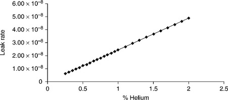
Figure 9.9 Plot of the change in scaled helium-leak rate vs helium content sealed or bombed into the package.
The data from Table 9.5 can also be used to calculate the minimum detectable helium content in a hermetic device. It is often desirable to set a baseline specification for a whole family of medical devices of similar size. An example is to determine the minimum helium content within a package if we establish a baseline leak rate of 9 × 10⁻⁹ atc.cc/s Helium. This can be determined as follows:
The leak rate spec of 2.43 × 10⁻⁸ atm.cc/s equates to 1% helium per Table 9.4.
Desired Leak Rate spec 9 × 10⁻⁹ atm.cc/s equates to X% helium.
Therefore X = (9 × 10⁻⁹ atm.cc/s)/(2.43 × 10−8 atm.cc/s) = 0.37% helium.
This type of calculation helps the process engineers set the sealing process to guarantee there is enough helium inventory in the sealed device to meet the requirements of the leak test.
Note that this helium limit could be further reduced if calibrated controls were available below 9 × 10⁻⁹ (and they are). Provided that calibration sources and controls are met, the detectable limit of helium and therefore the helium-gas content during the test can be extremely low. Note also that in a returned medical device many years old, the device could be quite hermetic and yet have no detectable helium tracer gas. It is therefore recommended that leak-rate testing include both a gross- and fine-leak-detection method.
9.4.3 Flow-rate detection
Several test systems are now available that use a technique to measure the actual flow rate of gas out of a sealed package. In this method, a sealed device is placed into a chamber of known fixed volume. A vacuum is imposed on the volume, and all residual gas is removed. As most devices are sealed at or near 1 atmosphere pressure, the vacuum imposes a pressure differential across the hermetic seal. The inner gases of the sealed device leak out, and the overall flow of gas is detected. Detection methods can use a variety of methods including flame ionization, heated filament/element, or calibration against a fixed and calibrated orifice plate. The heated filament and orifice plate are the most common. In the heated filament systems, the thermal conductivity of the escaping gases change the resistivity in the heated wire. This shift is proportional to the concentration and flow rate of the gases. Similarly, a calibrated orifice plate of fixed leak path length and diameter can be used. In this system, the detection gas is calibrated for flow through a know leak path (orifice). This is compared with the gases drawn out of the enclosure during test. The advantage of these systems is their increased sensitivity and detection limit. The test time can very rapid and many of these systems are used at-line and in-line for leak detection during production. Disadvantages are higher cost, inability to precisely locate a leak, and some difficulty in calibration. These systems must be carefully set up and tuned to the gases used.
A third method of flow-rate detection is pump down transients. This is especially effective with large-volume packages. The technique is fairly simple in that again the package is placed in a known-volume chamber and exposed to vacuum. As explained earlier the vacuum causes a pressure differential and the enclosed gases flow across the pressure gradient. If the package is leaking, the vacuum system must work much harder to exhaust the extra gases. The time and effort to pump down is a direct correlation of the leak rate. The easiest way to correlate the pump down transients is to confirm various leak rates of packages and then plot the vacuum pressure in torr vs time. Leaking packages will have a far higher time constant to reach low torr values than sealed units. The method is accurate, easy to implement, and yields a simple go no-go method amenable to at-line testing.
9.4.4 Enclosure stress state
An emerging method now finding acceptance is a novel technique that measures the stress state of the enclosure. The method begins in a similar manner to those suggested above where the package is exposed to a pressure differential. The pressure differential will cause the enclosure walls to bulge inward or outward depending on whether the outside environment is pressurized or de-pressurized. A laser beam is then used to reflect off the surface and measure the deflection. If the package is leaking, the degree of deflection is reduced as the package can quickly equilibrate to the pressure differential. Further, a set of calibration curves can be developed on leaking and non-leaking devices such that the degree of deflection versus pressure differential can be plotted. The rate of the deflection change with time can also be used to correlate to leak rate. This method has the advantage of speed, good low-leak-rate-detection limit, and is applicable to high-rate production. Disadvantages include the need for good uniformity of the surface condition, good control of the enclosure material properties, and the requirement for some level of laser safety.
9.5 References
1. Viswanadham, P., Singh, P.Failure Modes and Mechanisms in Electronic Packages. Chapman & Hall, 1998.
2. Ohring, M.Reliability and Failure of Electronic Materials and Devices. Academic Press, 1998.
3. Thompson, J.J.Conduction of Electricity through Gases. Wexford College Press, 2005.
4. Thomas, R.W.Moisture myths and microcircuits. RADC, 1972.
5. Pecht, M.G., Ardebili, H., Shukla, A.A., Hagge, J.K., Jennings, D. Moisture ingress into organic laminates. IEEE Trans. on Components and Packaging Technology. 1999; 22(1):104–110.
6. Wong, E.H., Rajoo, R. Moisture absorption and diffusion characterization of packaging materials-advanced treatment. Microelectronics Reliability. 2003; 43:2087–2096.
7. Mil Std 883, mil-c-38510 method 1014.11.
8. Amkor Technology. MQFP Moisture Absorption/Desorption Data, 2004. www.quicklogic.com/images/military_mqfp_moisture.pdf
9. Sorbent Systems. Desiccant Chart Comparisons, 2004. www.sorbentsystems.com/desiccants_charts.html
10. . CRC Handbook of Chemistry and Physics. 84th. CRC Press, Inc, 1982.:15–34.
11. Keller, S.W.Determination of the leak size critical to package sterility maintenance. Blacksburg, VA: VPI&SU, 1998. [PhD dissertation, Aug].
12. O’Hanlon, J.F.A User’s Guide to Vacuum Technology. John Wiley & Sons Inc, 2003.
13. Rack, P.D., Class notes on vacuum technology II, University of Tennyson, Department of Materials Science and Engineering.
14. Ely, K.J., Zhou, Y. Microjoining in medical components and devices. In: Zhou Y., ed. Chapter 23 in Microjoining and Nanojoining. Woodhead Publishing Limited, 2008.
15. Axelson, L., Calvin, S. Aseptic integrity and microhole determination of packages by gas leakage detection. Packaging Technology and Science. 1991; 4:9–20.
16. Greenhouse, H., Lowry, R., Romenesko, B. Hermeticity of Electronic Packages, 2nd. Elsevier Press, 2011.