
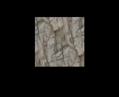
- Create a new material named
MyMaterial14. Also create two new shaders namedMyFragmentShader2andMyVertexShader2. Remember to copy the fragment and vertex program definitions in the material file. Add to the material file a texture unit with the rock texture:texture_unit { texture terr_rock6.jpg } - We need to add two new parameters to our fragment shader. The first is a two tuple of floats for the texture coordinates. Therefore, we also use the semantic to mark the parameter as the first texture coordinates we are using. The other new parameter is of type
sampler2D, which is another name for texture. Because the texture doesn't change on a per fragment basis, we mark it asuniform. This keyword indicates that the parameter value comes from outside the CG program and is set by the rendering environment, in our case, by Ogre 3D:void MyFragmentShader2(float2 uv : TEXCOORD0, out float4 color : COLOR, uniform sampler2D texture)
- In the fragment shader, replace the color assignment with the following line:
color = tex2D(texture, uv);
- The vertex shader also needs some new parameters one
float2for the incoming texture coordinates and onefloat2as the outgoing texture coordinates. Both are ourTEXCOORD0because one is the incoming and the other is the outgoingTEXCOORD0:void MyVertexShader2( float4 position : POSITION, out float4 oPosition : POSITION, float2 uv : TEXCOORD0, out float2 oUv : TEXCOORD0, uniform float4x4 worldViewMatrix)
- In the body, we calculate the outgoing position of the vertex:
oPosition = mul(worldViewMatrix, position);
- For the texture coordinates, we assign the incoming value to the outgoing value:
oUv = uv;
- Remember to change the used material in the application code, and then compile and run it. You should see the quad with the rock texture.
Step 1 just added a texture unit with the rock texture, nothing fancy. Step 2 added a float2 for saving the texture coordinates; also we are using sampler2D for the first time. sampler2D is just the name for a two-dimensional texture lookup function, and because it doesn't change per fragment and comes from outside the CG program, we declared it uniform. Step 3 used the tex2D function, which takes a sampler2D and float2 as the input parameter and returns a color as float4. This function uses the float2 as the position to retrieve a color from the sampler2D object and returns this color. Basically, it's just a lookup in the texture for the given coordinates. Step 4 added two texture coordinates to the vertex shader one as incoming and one as outgoing. Step 5 assigned the incoming to the outgoing parameter. The magic happens in the render pipeline.
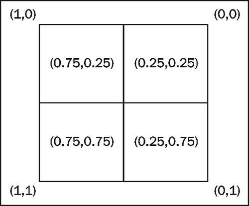
Our vertex shader gets each vertex and transforms it into camera space. After all vertices have gone through this transformation, the render pipeline sees which vertices form a triangle and then rasterizes them. In this process, the triangles get split into fragments. Each fragment is a candidate for becoming pixels on the screen. It will become pixels if it's not covered by another fragment and therefore can't be seen. During this process, the render pipeline interpolates the vertex data like texture coordinates over each fragment. After this process, each fragment has its own texture coordinate and we used this to look up the color value from the texture. The following image is an example of a quad, which is represented by four fragments. Each fragment has its own texture coordinates. It also shows how we can imagine the texture coordinates, related to the pixels. In the real world, this depends on the render pipeline and can change, but this is a helpful model we can think with, even if it's not 100 percent accurate.
The same interpolation is used when we assign each vertex a color. Let's investigate this effect a bit more.
Create a new vertex and fragment shader called MyVertexShader3 and MyFragmentShader3 respectively. The fragment shader should render everything in green and the vertex shader should calculate the position of the vertex in camera space and simply pass the texture coordinates to the fragment shader. The fragment shader doesn't do anything with them yet, but we will need them later.