
This time, we want to use the OctreeSceneManager, so we don't need the chooseSceneManager() function:
- We need an empty application:
class Example43 : public ExampleApplication { private: public: void createScene() { } }; - The first thing we need in the
createScene()function is a plane definition. We will use the plane as our ground for blades of grass:Ogre::Plane plane(Vector3::UNIT_Y, -10); Ogre::MeshManager::getSingleton().createPlane("plane", ResourceGroupManager::DEFAULT_RESOURCE_GROUP_NAME, plane, 1500,1500,200,200,true,1,5,5,Vector3::UNIT_Z); - Then instantiate the newly created plane and set a material. We will use the
GrassFloormaterial from the examples:Ogre::Entity* ent = mSceneMgr->createEntity("GrassPlane", "plane"); mSceneMgr->getRootSceneNode()->createChildSceneNode()->attachObject(ent); ent->setMaterialName("Examples/GrassFloor"); - Then also add a directional light to the scene; otherwise, it would be too dark to see something interesting:
Ogre::Light* light = mSceneMgr->createLight("Light1"); light->setType(Ogre::Light::LT_DIRECTIONAL); light->setDirection(Ogre::Vector3(1,-1,0)); - Now create a new
ManualObjectand call thebeginmethod:Ogre::ManualObject* manual = mSceneMgr->createManualObject("grass"); manual->begin("Examples/GrassBlades", RenderOperation::OT_TRIANGLE_LIST); - Add the first polygon with the position and texture coordinates for each vertex:
manual->position(5.0, 0.0, 0.0);
manual->textureCoord(1,1);
manual->position(-5.0, 10.0, 0.0);
manual->textureCoord(0,0);
manual->position(-5.0, 0.0, 0.0);
manual->textureCoord(0,1);
- We also need a second triangle to make the quad complete:
manual->position(5.0, 0.0, 0.0);
manual->textureCoord(1,1);
manual->position(5.0, 10.0, 0.0);
manual->textureCoord(1,0);
manual->position(-5.0, 10.0, 0.0);
manual->textureCoord(0,0);
- We have finished defining the quad; let's tell the manual object:
manual->end();
- Lastly, create a new scene node and attach the manual object to it:
Ogre::SceneNode* grassNode = mSceneMgr->getRootSceneNode()->createChildSceneNode("GrassNode2"); grassNode->attachObject(manual); - Compile the application and run it. The plane should have a grass texture, and there should be some blades of grass hovering slightly above the plane.
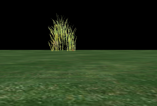
We painted our plane in a different color, this time a grass green; also, we created a quad and put an image of some blades of grass on it. Steps 1 to 4 should be easy to understand, as we have already covered this topic. The only difference is that we used a different material that is more appropriate for the application than the stones we had before. We will cover materials extensively in the next chapter.
In step 5, something new happened. We created a ManualObject.
A manual object is like a new code file. In the beginning it is empty, but a lot of different things can be created using it. Using a manual object, we can create 3D models. To create one, we need to give single vertices to describe triangles. We have already discussed that all objects we use in a 3D application consist of triangles. But for a quad, we need two triangles, which we will see soon.
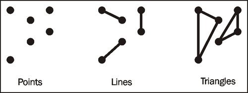
Step 5 created a new empty manual object and named it simply as grass. We then called the begin method, which prepared the manual object to receive its vertex information; a vertex is a single point in 3D space. The begin method needs a material name that the vertex will be using, the way we are going to input the vertex information, and what we want to create. There are six different ways for how and what we can put into a manual object. There are three different kinds of things we can create with a manual object, namely, points, lines, and triangles.
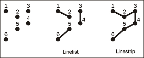
Points are simply stored as a list. Each time we add a new position, we create a new point. This mode is called OT_POINT_LIST. For lines, there are two different ways to create them. The straightforward way is to use the first and second position as the first line, the third and fourth position for the second line, and so on. This is called OT_LINE_LIST. Another way is to use the first two points as the first line and then each new point defines the end point of a new list and uses the last point as the beginning point for the line; this is an OT_LINE_STRIP.
As they are triangles, they can be defined in three ways. The first and simplest way is a triangle list: the first three points are triangle one, the next three are triangle two, and so on. This is known as an OT_TRIANGLE_LIST. Then we can use the first three points as the first triangle and each new point defines the next triangle using the last two points of the previous triangle. This is called OT_TRIANGLE_STRIP. The last option is to use the first three points for the first triangle and then always the first point and the last-used point with a new point for the next triangle.
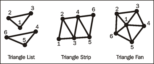
We see that, depending on the input mode, it takes more vertices to describe 3D figures. With a triangle list, we need three points for each triangle. With a strip or fan, we need three for the first and then only one new point for each triangle.
During the begin function call, we defined that we are going to use a triangle list to describe our quad. We want our quad to be 10 units long and 10 units high. Here is an image of the quad; it has four points and each point has its position labeled beside it.
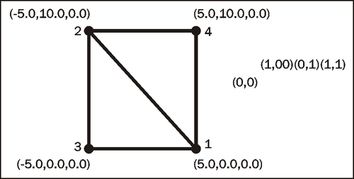
The first triangle needs points 1, 2, and 3. The second triangle needs the points 1, 2, and 4. Step 6 defined the first triangle points with the position() function call and step 7 used the position() function call to define triangle two. You probably noticed that after each position() function call, there was a textureCoord() function call.
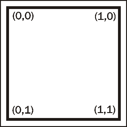
For Ogre 3D to be able to put an image of blades of grass onto our quad, each vertex needs texture coordinates besides its position. These consist of two tuples (u,v). (u,v) describes the location in the image, where u is the x-axis and v is the y-axis. (0,0) means the upper-left corner of the image and (1,1) the bottom-right corner.
If we use values greater than 1, several effects can happen, depending on the settings in the material. If we use the wrap mode, the texture is repeated. With clamp mode, each value created greater than 1.0 is reduced to 1.0. The same is true for values less than zero they will be set to zero. In mirror mode, one becomes zero and two becomes one. This mirrors the texture. If the values are greater than two, the original image is used again, after this the flipped, then the original, and so on. The last mode uses the defined border color and everything outside the [0,1] value range is rendered with the border color.
With texture coordinates applied, we have the following information for our quad:
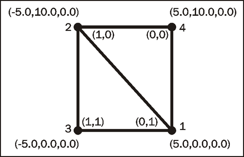
Take a look at steps 6 and 7. Compare the lines of code with the preceding picture. The position and texture coordinates should match.
Step 8 finished our manual object and step 9 created a scene node and attached our object to it so that it gets rendered.
Try the different ways of describing an object using a manual object. Also try lines and points. To make this process easier, use the material BaseWhiteNoLighting instead of the grass material. With this material, you don't need texture coordinates, as you can just use the position() function and experiment. Everything you create will be rendered as white.