Until now, we have always loaded a 3D model from a file. Now we will create one directly:
- Delete all the code inside the
createScene()function. - Add the following line to define a plane in the
createScene()function:Ogre::Plane plane(Vector3::UNIT_Y, -10);
- Now create the plane into your memory:
Ogre::MeshManager::getSingleton().createPlane("plane", ResourceGroupManager::DEFAULT_RESOURCE_GROUP_NAME, plane, 1500,1500,20,20,true,1,5,5,Vector3::UNIT_Z); - Create an instance of the plane:
Ogre::Entity* ent = mSceneMgr->createEntity("LightPlaneEntity", "plane"); - Attach the plane to the scene:
mSceneMgr->getRootSceneNode()->createChildSceneNode()->attachObject(ent);
- To get anything other than a white plane, set the material of the plane to an existing material:
ent->setMaterialName("Examples/BeachStones"); - Compile the application and run it. You should see some dark stones.
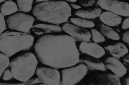
We have inverted the colors for ease of reading!
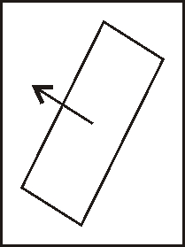
We just created a plane and added it to the scene. Step 2 created an instance of Ogre::Plane. This class describes a plane using the normal vector of the plane and an offset from the null point using the normal vector.
A normal vector (or in short, just normal) is an often-used construct in 3D graphics. The normal of a surface is a vector that stands perpendicular on this surface. The length of the normal is often 1 and is used extensively in computer graphics for light and occlusion calculation.
In Step 3, we used the plane definition to create a mesh out of it. To do this, we used the Ogre MeshManager. This manager manages meshes, which shouldn't be a surprise. Besides managing meshes that we loaded from a file, it can also create planes from our plane definition, as well as a lot of other things.
Ogre::MeshManager::getSingleton().createPlane("plane",
ResourceGroupManager::DEFAULT_RESOURCE_GROUP_NAME, plane,
1500,1500,20,20,true,1,5,5,Vector3::UNIT_Z);
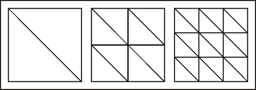
Besides the plane definition, we need to give the plane a name. When loading meshes from the disk, the file's name is used as the resource name, resource name. It also needs an resource group it belongs to, resource groups are like namespaces in C++. The third parameter is the plane definition and the fourth and fifth parameters are the size of the plane. The sixth and seventh parameters are used to say how many segments the plane should have. To understand what a segment is, we will take a small detour on how 3D models are represented in 3D space.
To render a 3D model, it needs to be described in a way a computer can understand and render it most effectively. The most common form to represent 3D models in real-time application is triangles. Our plane can be represented using two triangles to form a quad. With the segment option for the x-and the y-axis, we can control how many triangles are generated for the plane. In the following image, we see the triangles that make up the plane with one, two, or three segments for each axis. To see this effect, we start the application and then press the R key. This will switch the rendering mode first to wireframe mode, where we see the triangles. Another key press will change the mode to point mode, where we see only the points of the triangles. Another press will set the render mode to normal.
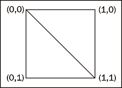
After we have defined how many segments we want, we pass a Boolean parameter which tells Ogre 3D that we want the normal of the plane to be calculated. As said before, a normal is a vector which stands vertically on the surface of the plane. The next three parameters are used for texturing. To texture something all points need texture coordinates. Texture coordinates tell the render engine how to map the texture onto the triangle. Because a picture is a 2D surface, the texture coordinates also consist of two values, namely, x and y. They are presented as a tuple (x,y). The value range of texture coordinates is normalized from zero to one. (0,0) means the upper-left corner of the texture and (1,1) the bottom-right corner. Sometimes the values can be greater than 1. This means that the texture could be repeated depending on the set mode. This topic will be explained in a later chapter extensively. (2,2) could repeat the texture twice across both axis. The tenth and eleventh parameters tell Ogre 3D how often we want the texture to be tiled across the plane. The ninth parameter defines how many textures' coordinates we want. This can be useful when working with more than one texture for one surface. The last parameter defines the "up" direction for our textures. This also affects how the texture coordinates are generated. We simply say that the z-axis should be "up" for our plane.
In step 4, we created an instance of the plane that we just created with the MeshManager. To do this, we need to use the name we gave the plane during creation. Step 5 attached the entity to the scene.
In step 6, we set a new material to the instance of the entity. Each entity has a material assigned to it. The material describes which texture to use, how the lighting interacts with the material, and much more. We will learn about all of this in the chapter on materials. The plane we created doesn't have a material yet and therefore would be rendered white. Because we want to see the effect of lights we create later, white isn't the best color to use. We used a material that is already defined in the media folder. This material simply adds a stone texture to our plane.