Basic principles of control systems in textile manufacturing
Abstract:
Robust control of machines and processes of textile manufacturing has become paramount during last few decades in order to cope with the stringent quality requirements. This chapter presents a brief account of basic control systems so that practising textile engineers can control processes effectively and efficiently. Details of various control strategies and their application for speed control have been considered in this chapter, along with design guidelines. Use of modern techniques of digital control and control with artificial intelligence has also been discussed in brief. A case study describing the application of two different techniques in textile manufacturing has also been presented with performance comparison.
2.1 Introduction
The demand for automatic control is becoming increasingly important in various industries. In manufacturing processes it ensures that certain physical parameters such as temperature, pressure, speed or voltage are maintained at optimum values in relation to other variables. In other words, the responsibility of control engineering is to bring these physical parameters to certain pre-defined values, set points (SP), and then maintain them. The design of a control system only makes sense if there is some objective or value that needs to be achieved to ensure a system performs as required, for example, maintaining a particular speed of rotation. Fundamental to any control system is the ability to measure the output of a system and to take corrective action if the output deviates from its desired value. In driving a vehicle for example, the action of steering is controlled by the feedback from driver’s senses. The eyes and ears transmit signals to the brain, which interprets this signal and transmits a signal to the arms to turn the steering wheel, adjusting the actual direction of movement to bring it in line with the desired direction. Thus, steering an automobile constitutes a feedback-control system.
An early example of a control system is the flyball governor, developed by James Watt in 1788 for controlling the speed of a steam engine. Another significant date in the history of automatic feedback-control systems is 1934 when Hazen’s paper ‘Theory of Servomechanisms’ was published in the Journal of the Franklin Institute, marking the beginning of intense interest in this new field. The word ‘servomechanism’ actually originated in this paper. The late 1950s saw the development of conventional classical control theory. The concept of an intelligent control system was first used in the 1990s with the development of fuzzy logic controllers, artificial neural networks, etc.
2.1.1 Principles of process control: open-loop and closed-loop control systems
The simplest form of control is open-loop control. In an open-loop control system an actuator is used to directly control the system output without utilising any information about the physical output. The actuator signal to the system is, therefore, unaffected by and unaware of the actual output of the system. The response of an open-loop system is only dependent on the characteristics of the system itself rather than the relationship between the output signal and system input.
One example of an open-loop control system is a separately excited d.c. motor, which is intended to drive the shaft of a machine tool as shown in Fig. 2.1. The spindle of the machine tool is required to be rotated at a constant speed, which is determined by the machine operator. In this system, for a fixed magnetic field, a required value of d.c. voltage (Vt) is applied to the armature of the d.c. motor to produce the desired motor speed. The output voltage (Vt) of the d.c. regulator (d.c.–d.c. converter) is determined by the d.c. supply voltage (VS) and operation duty cycle (k) of the converter. Very often the reference input or set point (SP) is directly related to the desired value of system output and thus the desired output parameter can be obtained by adjusting the SP by the operator. In the example of Fig. 2.1, the motor, along with the d.c. regulator, forms the system, the duty cycle is the input quantity, which is set by the actuator and the speed of the shaft is the output parameter.
The terminal voltage (Vt) applied to the d.c. motor by the d.c.–d.c. converter can be expressed as follows:
where Vt = motor terminal voltage, k = duty ratio of the d.c.–d.c. converter and VS = d.c. supply voltage.
In a separately excited motor with a fixed magnetic field excitation, like the one shown in Fig. 2.1, the speed of the motor (output) is a function of both the d.c. motor terminal voltage and the load torque. The machine tool will maintain a constant speed, provided there are no changes to either of these inputs. If the d.c. supply voltage (VS) to the regulator is varied however, then the d.c. motor terminal voltage (Vt) will be disturbed, and if the load on the motor is changed the current drawn by the motor from the d.c. regulator will change too. In either circumstance the speed of the motor (system output) will change and, in an open-loop system, there is no feedback to correct the input levels and reset them to the desired settings. The machine tool will therefore, maintain the new constant speed until either input function is altered.
In contrast to open-loop control systems, closed-loop control systems utilise the additional actions of measurement and feedback of the actual output quantity and compare it with the desired reference quantity at input. Using this feedback the actuator input signal can thereby be changed to achieve the desired output. In closed-loop systems then, the output value has a direct effect upon the input quantity. In the d.c. motor example, a person could be assigned the task of checking the actual speed of the motor (output) and comparing it with the desired reference speed (input). If the output did not have the desired value, the person could alter the duty ratio, k, of the d.c. regulator to achieve the desired motor speed. Introducing a person into the system provides a means through which the output is fed back and compared with the input. Any necessary changes can then be made in order to ensure that the output matches the desired value. The feedback action therefore controls the effective input to the dynamic unit. To improve the performance of closed-loop systems, so that the output quantity is as close as possible to the desired quantity, the person in this example can be replaced by any mechanical, electrical, or other form of feedback control unit capable of performing the same task.
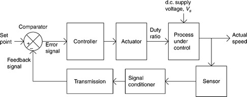
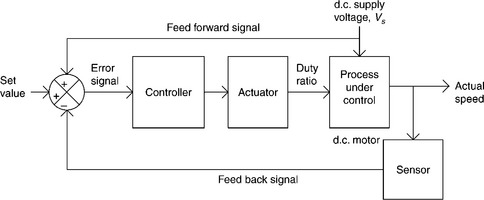
A closed-loop control system can be represented by a simplified block diagram containing all the essential components as shown in Fig. 2.2. In this example the sensor senses the physical parameter at the output and converts it into an equivalent electrical signal. This signal is then conditioned and transmitted to the comparator. The comparator compares the feedback signal to the reference signal, which is set to the desired output. The difference between these two signals is called the error signal. Based on the polarity and magnitude of the error signal, the controller sends a signal to the actuator detailing the necessary corrective measures to be taken. The actuator then adapts accordingly to attain the desired output of the system. In this way, the system can achieve the desired output regardless of disturbance from outside. The actuator in an automated process may in fact consist of a combination of several actuators, each providing an output that drives the following one in a predetermined sequence. Once feedback is applied, the system becomes a closed loop. Closed-loop systems can achieve far greater accuracy than open-loop systems, although they rely entirely on the accuracy of the comparison between the desired and the actual output values and, therefore, on the accuracy of the measured output value.
2.1.2 Feedback and feed-forward control
In a feedback-control system, the corrective action starts only if there is deviation of the output variable from its expected value. In the d.c. drive in Fig. 2.1 for example, if the d.c. supply voltage changes, then the speed of the motor deviates from the reference speed and the comparator generates an error signal for the controller. The controller now acts accordingly and sends the necessary signal to the actuator to minimise the deviation. If the system works with a long time constant, then it will be some time before any corrective action takes place.
If, however, the change in d.c. supply voltage can be measured as soon as it occurs and the information is forwarded directly to the controller, then necessary action can be taken immediately by sending a signal to the actuator before any deviation in output behaviour. Thus, a system with feed-forward control can take necessary corrective action as soon as any measurable disturbance occurs in the system. In this way feed-forward control can minimise the transient error even if large and frequent disturbances occur in the system. The limitation of feed-forward control, however is that this method can only account for measurable disturbances. It would therefore, be advantageous to include a feedback control loop in addition to feed-forward control, if there is any possibility of unmeasurable disturbance occurring in the system.
2.2 Components of control systems
The sequential tasks performed by a control system are measurement of actual output quantity by suitable sensor or transducer, transmission of the measured variable after proper conditioning, comparison of the signal with the desired reference quantity at input and then performing the task of taking corrective action by the controller, if the output deviates from its desired value. Thus, a control system is composed of various basic components.
2.2.1 Sensors/transducers
In most control systems, the appropriate physical parameter of a system (e.g. displacement, speed, temperature, pressure, etc.) intended to be controlled at the desired level is sensed and converted into an equivalent electrical quantity, by a device called a transducer. Some commonly used transducers are:
| Position transducer: | Potentiometer, LVDT, optical encoder, synchros. |
| Motion transducer: | LVDT. |
| Temperature transducer: | Thermocouple, thermistor, RTD. |
| Force transducer: | Strain gauge, load cell. |
| Flow transducer: | Orifice plate, venture tube, Pitot tube. |
| Pressure transducer: | Diaphragm, bellows, Bourdon tube. |
2.2.2 Signal conditioner and transmitter
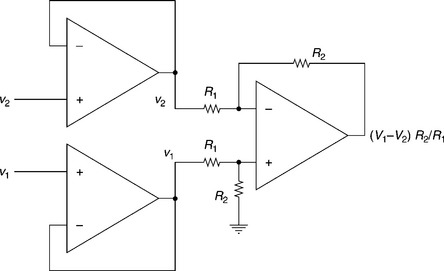
In many applications, the transducer is used as one of the four arms of a Wheatstone bridge in order to properly sense the electrical signal obtained from the transducer. The transducer signal is then obtained as a difference in voltage across the arm containing the transducer. The electrical signal generated by transducers is often too low in voltage and power level to be transmitted and compared by the controller. To increase the strength of this signal, instrumentation amplifiers, such those shown in Fig. 2.3, are used. The instrumentation amplifier uses an operational amplifier (OPAMP) as a differential amplifier tool to sense the difference between the signal from the transducer and the reference signal, while rejecting the common mode signal. The two OPAMPs used at the inputs of the instrumentation amplifier act only as unity gain buffer. They electrically isolate the part of the transducer directly connected to the actual physical system, often functioning at a high voltage, from the expensive control unit, thereby eliminating the risk of extensive damage to the control unit (e.g. computer system, its peripherals, etc.) and of fatal accidents to operating personnel. The input OPAMPs also have high input resistance and thus avoid causing any electrical loading to the low-power transducer signal.
In most process industries, the transducers are installed at the load (process) end and the controllers are installed at the central control unit, which may be far away from the load point. Transmission of the transducer signal over a long distance may result in a considerable loss in signal quantity, random electromagnetic interference (EMI) from neighbouring power sources and radio frequency interference (RFI) noise from communication systems. All these factors may alter the quality of the actual feedback signal. In such cases, therefore, it is necessary for signal transmission to be made through shielded cables, which are grounded at regular intervals so that vast majority of noise signals pass into the ground through a low resistance path without causing any interference to the transducer signal.
2.2.3 Comparator and controller
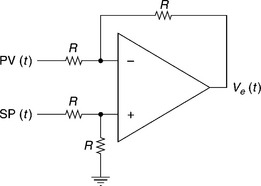
The comparator and controller form the central and intelligent section of the control system. The comparator has two inputs: the SP indicates the reference value of the parameter and the process variable (PV) indicates the actual value of the parameter. The comparator compares these two signals to obtain the error signal, Ve(t). Based on the polarity and magnitude of the error signal, the controller drives the actuator to modify the process in such a way as to make the PV equal to the SP. Thus, the comparator always consists of an error amplifier followed by the main controller, though its type might vary depending on the process requirements. An error amplifier can easily be created electronically using an OPAMP in subtraction mode, as in Fig. 2.4. The output of the OPAMP is the error signal given by Ve(t) = SP – PV.
2.2.4 ON–OFF controller
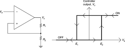
The ON–OFF controller’s output is either fully ON or fully OFF, based on the PV and whether it is below or above set point. For practical applications, however, an ON–OFF controller should always have a dead band or hysteresis to prevent excessive cycling or chattering. Whether the controller is ON or OFF is dictated by the error signal. When the error signal exceeds a specified limit, the controller turns ON, and if the error signal falls below another specified limit the controller turns OFF. An electronic version of an ON–OFF controller using an OPAMP is illustrated in Fig. 2.5.
In this example, the controller in its OFF condition only switches to ON when the error signal Ve exceeds the level of E2, given by
where VSat is the saturation output voltage of OPAMP at OFF state and vice versa; once the controller is turned ON, it will turn OFF again only when the error signal, Ve falls below the level of E1 given by
2.2.5 Proportional (P-)controller
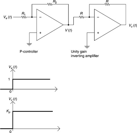
In a P-controller the output is proportional to the error signal, Ve. A P-controller using an OPAMP is illustrated in Fig. 2.6, along with its response for a unit step error signal. As the OPAMP used in this configuration acts inversely, a second OPAMP is used in unity gain inverting amplifier mode to re-invert the inverted signal.
The output of first stage OPAMP (P-controller) is given by
where Kp = R2/R1; Kp is called the proportional constant.
The output of second stage of OPAMP (unity gain inverting amplifier) is given by
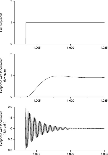
The P-controller is very fast and responds immediately and proportionally to the error signal, that is, according to variations in the PVs relative to the reference set point. If the error signal is zero, then a zero signal will be sent by the P-controller to the actuator. This is not desirable, since a non-zero signal is required for the actuator to provide an output. Referring back to the d.c. drive example in Fig. 2.1, when the speed of the d.c. motor deviates from the reference speed, the error signal, representing the difference between the reference speed and the actual speed, sends a proportional signal to the actuator. The actuator then modifies the speed of the motor accordingly. If the motor attains the reference speed, however, then the error signal will be zero, which will produce a zero signal for the actuator and mean no output. To ensure that the actual speed follows the reference speed in a steady state, a specified non-zero signal for the actuator must exist to ensure constant output. P-controllers, therefore, have a specified non-zero value error signal called a ‘steady-state error’ or ‘off-set’ error of the P-controller. The steady-state error of the P-controller can be greatly reduced by selecting a large gain for the controller, but this may also cause system oscillation and reduce the stability of the system, as shown in the following example.
If we model the d.c motor of Fig. 2.1 with following parameters it can then be considered as test model in subsequent sections for computer simulation:
Armature inductance, La = 1.5 mH
Frictional coefficient of load, B = 0.0001 Nm/rad/s
Inertia constant of load and motor, J = 0.00025 Nm/rad/s2
In order to verify the dependence of performance on the proportional constant, the P-controller has been tested under a closed-loop control with small and large values of Kp. The response (output) for unit step input (set point) is shown in Fig. 2.7. It can be seen that, for a small value of Kp, the system output has a steady-state error, that is, the output is much less than unity at steady state. However, with large value of Kp, the steady-state error is minimised, but at the cost of system oscillations at the output.
2.2.6 Integral (I-)controller
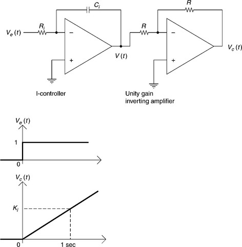
The I-controller works on the principle that the rate of change in output is proportional to that given by the error signal. An OPAMP based I-controller and its response to a unit step error signal is shown in Fig. 2.8. The output of the integral controller is given by
where Ki = 1/RiCi ; Ki is called the integral constant.
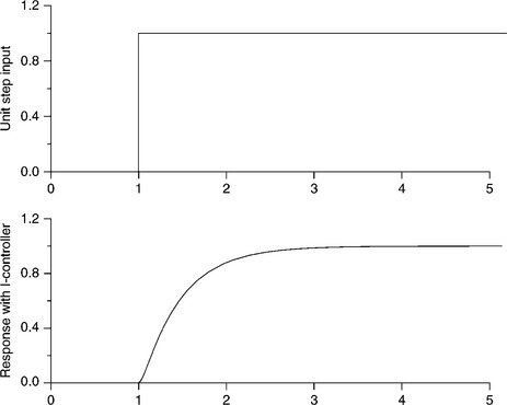
An I-controller will respond rapidly to a large error signal, swiftly changing its output to correct the error. As the error gets smaller, however, the controller’s output will change more slowly. Once the error signal has been reduced to zero, there will not be any change in the controller’s output. Thus, the integral controller is a relatively slow controller and it acts until the error signal disappears. The I-controller’s performance in the closed-loop control of a d.c. drive has been verified through computer simulation. The step input response of the system is shown in Fig. 2.9.
2.2.7 Proportional-integral (Pl-)controller
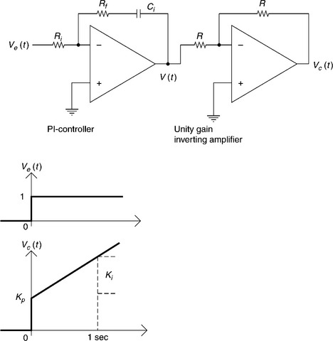
The I-controller has very poor transient response. Upon the occurrence of a step error signal the P-controller will immediately respond by stepping its output proportionally. The I-controller, however, will start changing its output continuously until all steady-state error has been eliminated. Thus, a P-controller is more useful for attaining a fast transient response, whilst an I-controller can minimise the steady-state error. The advantages of both these controllers can be obtained when their features are combined into a single controller to form a PI-controller, as shown in Fig. 2.10 along with its step input response. A PI-controller can also be developed by paralleling separate blocks of a P- and an I- controller. This configuration has the advantage of easy and independent adjustment of Kp and Kf.
The output of a PI-controller is given by
where Kp = Rf/Ri. and Ki. = 1/RiCi;Kp and Ki. are proportional and integral constant, respectively.
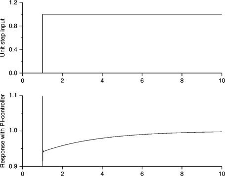
The response of the PI-controller for closed-loop control of the test d.c. drive has been simulated and is presented in Fig. 2.11.
2.2.8 Derivative (D-)controller
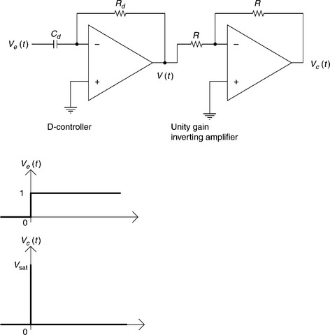
The PI-controller can provide a fast transient response as well as a good steady-state error. However, processes with large inertia (motors, etc.) require some form of additional kick, along with their response to the step error signal, in order to overcome their inertia and to respond much faster to error steps than can be achieved with a P-controller. This improved transient response can be provided by a D-controller. The output of a D-controller is proportional to the rate of change in the error signal. Figure 2.12 shows an electronic D-controller and its unit step response. The D-controller produces an output only when there are changes in the error signal. However, the output of the D-controller is limited to VSat, the saturation voltage of a practical OPAMP. Thus, even a system with a large constant error will have no output other than at the instant of the occurrence of the error signal. D-controllers are, therefore, only used in combination with a P- or a PI-controller.
2.2.9 Proportional-integral-derivative (PID-) or three term controller
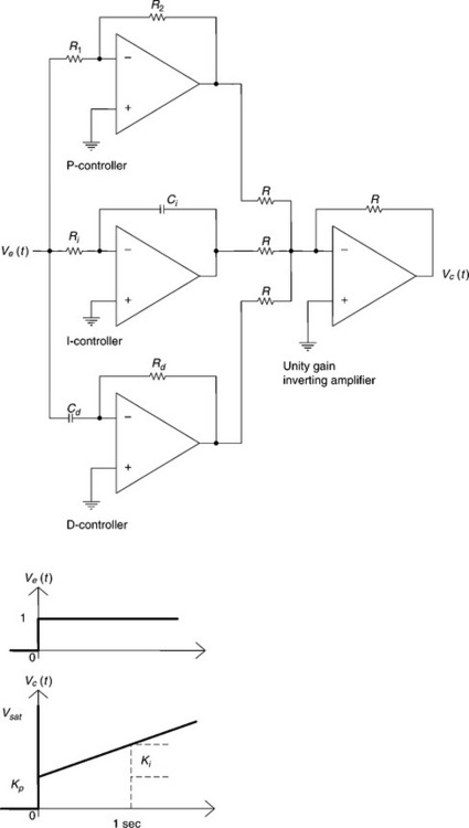
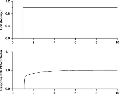
A three term or proportional-integral-derivative (PID)-controller can be formed by combining a P-controller, an I-controller and a D-controller to create a single controller or a parallel combination of three separate controllers (P, I and D), as shown in Fig. 2.13 along with its unit step response. PID-controllers provide a rapid transient response and eliminate the steady-state error. The PID-controller is the dominant control structure used in industrial control due to the fact that it offers a practical and inexpensive solution to the majority of processes that can be approximated by low-order dynamics.
The performance of a PID-controller for closed-loop control of the d.c. drive has been verified under test conditions. The simulated unit step response is shown in Fig. 2.14.
2.3 The control system design process
One disadvantage of using a feedback-control system is the oscillations at the output, which are otherwise not present as long as the system operates in open-loop mode. The oscillations are due to an attempt by the controller to change the system output to minimise the error signal as much as possible. Thus, the output swings first in one direction and then to the other, thereby gradually reducing the variation. The advantages of using closed-loop systems are obtained therefore at the expense of system stability.
Before implementation of a closed-loop control system, a suitable controller first needs to be selected and properly designed so that it can tightly regulate the output within appropriate limits. The controller is intended to send the required signal to the actuator based on all possible error signals. So, if the controller is not selected or designed properly, then, on occurrence of an error signal, it may over-compensate the system output by sending a signal to the actuator of a magnitude much higher or lower than actually required. Any over-compensation of output will further increase the error signal and as a result, the faulty controller may further deviate the output from the expected range. This cumulative effect may ultimately bring the system out of stabilisation. Therefore, before actual implementation of the controller, the closed-loop control system needs to be simulated, tested and analysed using all the worst-case error signals.
2.3.1 The transfer function in process control systems
During the simulation and testing of a closed-loop control system all the blocks of the system need to be represented by their transfer functions, which characterise the input–output relationship of each component. The transfer function is defined as the ratio of the Laplace transform of the output (response function) to the Laplace transform of the input (driving function) under the assumption that all initial conditions are zero, and it is obtained from the system mathematical model that is a set of linear, differential equations describing the system dynamics and the functions performed by each component in that system. Figure 2.15 shows the block diagram of the dc drive system along with the transfer function of each block.
As an example, the dynamic behaviour of the d.c. motor with a fixed magnetic field excitation of Fig. 2.1 can be expressed by the following differential equations:
Again, the dynamic torque expression of the motor is given by
where Te = Kt ia = Electromagnetic torque developed by d.c. motor
Thus, the open-loop control system of Fig. 2.1, can be represented by a mathematical model comprising the above differential equations and the transfer function of the complete system can be defined,
2.3.2 Determination of controller key parameters
The design of a control system is an important and specific part of engineering design. The goal of control system design is to obtain the correct configuration, specification and determination of key parameters necessary for the controller to meet the specific system requirements.
The first task of control system design is modelling the process, which means expressing the physical system under examination in terms of a mathematical model that can be easily dealt with and understood. A model can often be made up of a complicated collection of identities and equalities even for apparently simple systems, and particularly when attempting to account for all possible eventualities. Control system implementation with such types of models can lead to an extremely costly design exercise, due to the time taken to attain an optimum performance in the presence of many complexities. Conversely, if the model describing a physical system is over simplified, such that important properties of the system are not included, then it may lead to an incorrect analysis and an inadequate controller design. A certain amount of common sense and practical experience is therefore necessary when forming a mathematical model of a physical system, in order to decide which characteristics of the system are important within the confines of the particular set-up in which the system has to operate.
Once a physical system has been modelled, the Laplace transform method is invoked to determine the transfer function of the system, which is used in subsequent design and analysis stages.
The next step in control system analysis is the design stage, in which a suitable control strategy is selected in order to achieve the desired system performance. The previously obtained system model is greatly used during this stage. Adjustment of the parameters of the controller is carried out in this stage through successive iteration until the performance specifications are met. If the performance meets the specifications, then the design is finalised. Once the design is complete, the controller is often implemented into the hardware. Upon arrival at the site where the system will be used, however, the parameters of the controller are often retuned in order to optimise its performance.
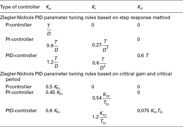
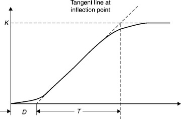
The design of controller parameters Kp, Ki and/or Kd can be carried out with optimum system performance using classical control system-design techniques such as Routh-Harwitch criteria, Root locus analysis, Bode plot and Nyquist criteria. Use of these techniques involves considerable mathematics. An easier, but relatively less accurate empirical method, the ‘Step Response Process Reaction Method’ suggested by Ziegler-Nichols4 is still in use for many process control systems whose open-loop step response is nearly S-shaped as shown in Fig. 2.17. The S-shaped curve may be characterised by two constants, ‘delay time’ (D), also called ‘transportation lag’, and ‘time constant’ (T). The delay time and time constant are determined by drawing a tangent line at the inflection point of the S-shaped curve and determining the intersections of the tangent line with the time axis. Once these two parameters are determined, the parameters of the PID-controller can be determined from the empirical relations given in Table 2.1.
The process reaction method cannot, however, be used in systems in which the open-loop step response has a large overshoot. For such systems, another empirical method, called the ‘continually cycling method’, suggested by Ziegler-Nichols4 can be useful. In this process, the system is first tested in a closed loop with only a P-controller. The gain of the P-controller is increased until the system controlled output oscillates continually with constant amplitude. At this stage, the controller gain is called the ‘ultimate gain’ (KCr) and the time period of oscillation is called the ‘ultimate period’ (TCr). Once KCr and TCr have been established, the parameters of the PID-controller can be calculated, as shown in Table 2.1.
2.4 Digital control systems
The extraordinary development of digital computers (microprocessors, microcontrollers) and their extensive use as controllers in a variety of fields and applications, has brought about important changes in the design of control systems. The superior performance, low cost and design flexibility now available in various types of control systems has significantly increased the popularity of digital controllers over analogue controllers in many applications.
In principle, a digital control system is similar to an analogue control system. Here, the analogue controller block is replaced with a digital computer, which performs the task of generating the required signal for the actuator, as shown in Fig. 2.18. Since digital computers deal only with binary numbers, an analogue-to-digital (A/D) converter is required before the controller stage for converting the analogue error signal into digital form. It does so by sampling the analogue signal at periodic intervals and then holding over the sampling interval. Conversely, a digital-to-analogue (D/A) converter is also required after the controller stage as the actuator operates on the analogue signal.
The digital controllers have several advantages over analogue schemes, some of which are as follows:
• Flexibility in control action: modification of an analogue controller can only be made through rewiring and replacement of a component, whereas a simple change to the computer program is all that is required for the modification of a digital controller.
• Reduced cost involvement for addition of further control loops: the addition of extra loops in digital controllers merely requires any extra hardware to be connected up to the same computer, whereas additional hardware loops would otherwise be required for an analogue controller.
• Improved user interface: digital controller information can be displayed graphically on a monitor when required, as opposed to the analogue alternative of employing a large panel for displaying limited information.
• Adaptive control: digital controllers can be modified online, that is, even when the system is in operation.
• Cost effective: due to the rapid development of VLSI technology, the cost of digital controllers is decreasing in comparison to that of analogue controllers, especially for applications requiring high accuracy and optimum performance.
2.5 Intelligent control systems using soft computing
Artificial intelligence (AI) has been used in industrial applications since the early 1960s – mostly in the area of expert knowledge-based decision making for the design and monitoring of industrial products or processes. Fuzzy logic control (FLC) has gained great popularity in many applications due to its ability to control nonlinear, uncertain systems even in processes for which no mathematical model is available. FLCs are based on fuzzy logic and constitute a method of converting linguistic expressions into a suitable control strategy through the interaction of a rule base, which controls the behaviour of the system. There is, however, no well-defined or systematic method for designing and tuning the FLC for cases where expert knowledge is not available.
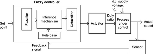
The application of a FLC for speed control of a separately excited d.c. motor is shown in Fig. 2.19. The fuzzy controller block contains four components: fuzzifier, rule base, inference engine and defuzzifier.
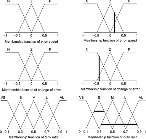
The fuzzifier transforms the analogue (continuous) input variables into membership functions. A membership function is a typical curve that converts the crisp inputs into fuzzy membership values (from 0 to 1), indicating the level of acceptability of the inputs to a fuzzy set. Membership functions can take various forms such as triangular, trapezoidal or Gaussian of which a triangular membership function is the simplest and most commonly used. In the example of speed control of a d.c. motor by a fuzzy controller, the selected input variables are error speed (deviation of actual speed from reference speed) and change of error speed. These are transformed into membership functions of negative (N), zero (Z) and positive (P) as shown in Fig. 2.20. The output variable of the controller for the actuator is the duty ratio, which is represented by the membership functions of very small (VS), small (S), medium (M), large (L) and very large (VL).
The next block of the fuzzy controller is the fuzzy inference mechanism, which maps input linguistic variables into output linguistic variables on the basis of fuzzy rules.
A fuzzy rule consists of two parts, the first of which is an ‘IF’ or ‘antecedent’ statement and the second is a ‘THEN’ or ‘consequent’ statement. The antecedent part joins the input membership functions with logical operators such as ‘AND’ or ‘OR’. The consequent part deals with the output membership functions. Fuzzy rules provide quantitative reasoning, which relate input fuzzy sets to output fuzzy sets. In the present example, the following base rules are formulated based on experts’ knowledge for speed control of a d.c. motor.
IF error speed is negative AND change of error is negative THEN duty ratio is very small.
IF error speed is negative AND change of error is zero THEN duty ratio is small.
IF error speed is zero AND change of error is negative THEN duty ratio is small.
IF error speed is zero AND change of error is zero THEN duty ratio is medium.
IF error speed is zero AND change of error is positive THEN duty ratio is large.
IF error speed is positive AND change of error is zero THEN duty ratio is large.
IF error speed is positive AND change of error is positive THEN duty ratio is very large.
The output of each fuzzy rule is also called a ‘fuzzy set’. All output fuzzy sets are aggregated into a single fuzzy set typically by a ‘max’ operator. This step is known as ‘aggregation’. Finally, the resulting fuzzy set is resolved into a single crisp number by ‘defuzzification’. There are several methods of defuzzification such as ‘centre of gravity’ (centroid), ‘centre of sums’, ‘mean of maxima’ and ‘left-right maxima’. The calculation of crisp output in the centre of gravity method10 is achieved using the following mathematical expression:
Basic principles of control systems in textile manufacturing
where x* is the defuzzified output and μA(x) is the output fuzzy set after the aggregation of individual implication results.
In the present example, an arbitrary error speed of 0.3 and a change of error of − 0.4 is assumed for the d.c. drive under consideration. An error speed of 0.3 cuts the zero error speed membership function at 0.6 and the positive error speed membership function at 0.4. Again, the change in error speed of − 0.4 cuts the zero change of the error membership function at 0.2 and the negative change of error membership function at 0.8. These conditions fire third, fourth and sixth rules and correspond to the duty ratio of small membership function of 0.6, medium membership function of 0.2 and large membership function of 0.2. After defuzzification the intended duty cycle was found to be 0.42.
2.6 Application of control systems in textile processing
The scope of potential applications of various control systems in currently used textile machines and processes is enormous. Control of the warp tension is paramount in weaving as the end-breakage rate and machine efficiency is largely dependent on it. Mehmet, Hakan and Cengiz11 demonstrated the use of PID and fuzzy controller in the let-off system of weaving. In this system, the floating backrest of a loom is pressed in a downward direction as the tension increases in the warp sheet. A proximity sensor is used to monitor the movement of the backrest and an encoder is used to identify the angular position of the main shaft. The signal generated by the proximity sensor is compared with the preset reference value to generate the error signal. This signal is then transmitted to the servo motor, which rotates the weaver’s beam to release the warp sheet. Both PID and fuzzy controllers have been used for this type of work and a comparative performance analysis reveals that it is fuzzy controllers that achieve the minimum warp tension as well as the lowest warp breakage rate. Some modern drawframes used in the spinning process also use such soft computing-based control systems to achieve the highest quality results.
2.7 References
1. Burns, Ronald S. Advanced Control Engineering. Oxford, U.K.: Butterworth-Heinemann; 2001.
2. Warwick, Kevin. An Introduction To Control Systems. Singapore: World Scientific Publishing Co. Pte. Ltd.; 1996.
3. Schleicher, Manfred, Blasinger, Frank. Control Engineering: A Guide for Beginners. KG, Fulda, Germany: JUMO GmbH & Co; 2003.
4. Ogata, Katsuhiko. Modern Control Engineering. Ltd, India: Prentice-Hall of India Pvt; 1996.
5. D’Azzo, John J., Houpis, Constantine H., Sheldon, Stuart N. Linear Control System Analysis and Design with Matlab. USA: Marcel Dekker, Inc.; 2003.
6. Zilouchian, Ali, Jamshidi, Mo. Intelligent Control Systems Using Soft Computing Methodologies. USA: CRC Press; 2001.
7. Michael Jacob, J. Industrial Control Electronics: Applications and Design. USA: Prentice-Hall International Inc.; 1989.
8. Frohr, Friedrich, Orttenburger, Fritz. Introduction to Electronic Control Engineering. London: Wiley Eastern Limited; 1992.
9. Nagrath, I.J., Gopal, M. Control Systems Engineering. India: Wiley Eastern Limited; 1992.
10. Passino, Kevin M., Yurkovich, Stephen. Fuzzy Control. California, USA: Addison Wesley Longman, Inc.; 1998.
11. Mehmeta, Dayik, Hakanb, Calis, Cengiz, Kacacan M. Adaptive control of let-off system in weaving, The Journal of The Textile Institute, 100(2). March. 2009; 2009:186–194.


