Process control in apparel manufacturing
Abstract:
The quality of apparel is not only affected by the quality of the fabrics used in its manufacture but also by factors determined by the technology and parameters of the apparel manufacturing process. The selection and use of the processes and parameters can ultimately affect the apparel quality. In this chapter, process control issues relating to apparel manufacturing, such as spreading, pattern making, cutting, sewing, fusing, pressing and packaging are discussed. Quality evaluation of apparel and accessories is also discussed.
16.1 Introduction
Fabric is the basic raw material of apparel industry. The main task for the apparel manufacturer is to produce shell structures out of flat fabrics to match the shape of human body. The conversion of fabric into apparel involves various processes, such as spreading, pattern making, cutting, sewing, fusing, pressing and packaging. The quality of apparel is not only affected by the quality of the fabrics used in its manufacture but also by the factors determined by the technology and parameters of the apparel manufacturing process. The selection and use of the processes and parameters can ultimately affect the apparel quality (Fan and Hunter, 2009). In this chapter, process control issues relating to apparel manufacturing, such as spreading, pattern making, cutting, sewing, fusing, pressing and packaging are discussed. Quality evaluation of apparel and accessories are also discussed.
16.2 Process control in spreading, pattern making and cutting
In addition to the quality of fabric used for apparel manufacture, selection of suitable apparel preparatory processes such as spreading, pattern making and cutting also influence the quality of apparel considerably. The following section discusses the process control issues relating to spreading, pattern making and cutting.
16.2.1 Spreading
Spreading is the process of stacking the material one layer on top of another to create a lay. The lay can be a single ply of fabric or several hundred plies. Various factors that can affect spreading should be checked, such as ply alignment, ply tension or slackness, bowing and splicing (Kothari, 1999a; Solinger, 1980).
The greater the variation in width or length alignment, the greater the waste in precision cutting because the ends and sides must be trimmed to the narrowest and shortest plies. A tight spread will contract after cutting, resulting in components that are smaller and skimpier than they should be. A slack spread possesses excess length within the stipulated end of the spread. Cut components from slack spread will tend to be oversized. Bowing is the distortion of filling yarn from a straight line across the width of a fabric. This will cause unbalanced stresses in the fabric, resulting in slackness and tightness in the ply that will lead to undersized components. Also, the component containing such a defect will tend to twist or distort in laundering or dry-cleaning. Splicing is the overlapping of two ends of fabric in a ply. A short or insufficient overlap will result in incompletely cut pattern sections and a long overlap will result in waste. Static electricity in fabric may cause a distorted spread, resulting in incompletely cut pattern sections. Static electricity can be eliminated by either increasing the humidity in the cutting room or using static eliminators.
16.2.2 Pattern making
Various pattern defects that may arise during pattern making process are as follows (Carr and Latham, 1994; Kothari, 1999a):
• Pattern alignment in relation to the grain of the fabric: Pattern pieces normally carry a grain line. When pattern pieces are laid down on the piece of cloth, the grain line should lie parallel to the line of the warp in a woven fabric or the wales in a knitted fabric. When pattern pieces are laid across the piece, the grain line should lie parallel to the line of the weft in a woven fabric or the course in a knitted fabric. In bias cutting, which is often used in large pattern pieces as part of the apparel style in ladies dresses and lingerie, as well as in small pattern pieces such as pocket facings and undercollars in menswear as a requirement of satisfactory apparel assembly, the grain lines will be at 45 °C to the warp. The designer or pattern cutter may define a tolerance that allows the marker planner to swing the grain line a small amount from parallel. If the marker planner lays down a pattern outside the stated rules for grain lines, then the finished apparel will not hang and drape correctly when worn.
• Mixed pattern parts: Parts not correctly labelled in marker, therefore a marriage of wrong-sized parts
• Line definition poor: Poor line definition (e.g. chalk too thick, indistinctly printed line, perforated lay not fully powdered), leading to inaccurate cutting
• Skimpy marking: Either the marker did not use the outside edge of the pattern or the pattern was moved or swung after partial marking to squeeze the pattern into a smaller space in the interests of fabric economy. Alternatively, the pattern is worn around the edges and should be replaced.
• Marker too wide: Apparel parts at the edge of the lay are cut with bits missing
16.2.3 Cutting
Cutting quality is a prerequisite for quality in a finished product. In addition, cut work quality affects the case and cost with which construction is accomplished. The quality of work leaving the cutting room is determined by how true the cut fabric parts are to the pattern; how smooth or rough the cut surface is; material or fabric defects in the cut fabric parts; shade differences between cut fabric pieces within a bundle. In addition, various factors in cutting that can affect the subsequent quality should be checked, such as under or overcut, size, placement and sequence alignment of notches and drill holes, ripped or pulled yarns, etc. Here are some defects that may arise in cutting (Anon, 2010; Carr and Latham, 1994; Kothari, 1999b):
• Frayed edges: May impede cutting time by clogging the knife action and/or spoil the fabric with rips or pulled yarns. The amount of fraying depends on fabric construction and finish. Improper cutting tools or dull knives cause excessive fraying in a pattern as the section is cut.
• Fuzzy, ragged, or serrated edges. The result of poor cutting implements. Such edges will impede sewing and/or diminish sewing quality. Such a condition is caused by faulty knife edges such as burrs, chips, or dullness.
• Ply-to-ply fusion: More common and troublesome. Adjacent plies in a block are fused together, which makes it difficult for the sewing machine operator to pick up a single ply quickly. Fusion occurs due to heat created by excessively high speed of cutting or by the friction of a dull knife. To prevent fusion, check knife speed, keep knives sharp, place wax paper between fabric plies, and lubricate the cutting blade.
• Single-edge fusion. Consists of a single ply whose cut yarn ends are fused to form a hard brittle rim on the cut edges. Sometimes, this is desirable to prevent fraying; however, hardness and brittleness are undesirable if they impede sewing manipulation or may result in seams uncomfortable to the consumer.
• Pattern precision. Misshaping or distortion of the pattern perimeter as cut. Whether it is under or overcut is due to poor manual control of the cutting machine and poor lines on the marker. To assure precision in a pattern, check markers before cutting, use tensionless spreading, or allow time for the fabric to relax. After a cut, check the top, bottom and middle plies against the pattern.
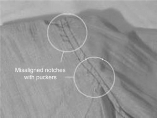
• Notches . Notch size refers to the depth of a notch. If the depth is too great, the notch may show after sewing. If the notches are too small, sewing operators may have difficulty locating them quickly, resulting in decreased efficiency. Misplacement of a notch may be due to an improperly spread marker, poor control of a cutting machine with the cutter's notching tool stroking diagonally instead of vertically, incorrect marker in that the notches formatting parts do not coincide. Check notch placement against matching pieces. Quality control in stitching may be a problem if notches are not aligned (Fig. 16.1).
• Drilling. The drill hole may be too small in diameter. In addition, a drill may become too hot due to high speed or wrong size, causing the plies to fuse at the drill hole. The drill must stroke vertically to the table for uniform placement throughout the bundle. Sometimes fabric properties are such that the slight movement of yarns in a fabric would close a drill hole. In such cases, it is necessary to drill holes with a marking fluid. The drill used for such a purpose is hollow and carries marking fluid (ink) that is deposited at the drill point on the fabric as the needle is withdrawn. Such marks should last long enough so that further processing can be finished without difficulty, but should be easily removable after processing or in case of an error.
16.3 Process control in sewing
Sewing damage is a problem in apparel production, causing minor appearance problems. The problems are most conveniently divided into (Carr and Latham, 1994, 2000):
• Problems of stitch formation, giving rise to poor seam appearance and performance;
• Problems of fabric distortion known as pucker, also giving rise to poor seam appearance;
16.3.1 Stitching defects and control
The main problems that arise from the actual stitch formation include skip or slipped stitches, staggered stitches, unbalanced stitches, variable stitch density and needle, bobbin or looper thread breakage (Anon, 2010; Carr and Latham, 1994, 2000).
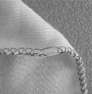
Skip or slipped stitches (Fig. 16.2) arise from the hook or looper in the machine not picking up the loop in the needle thread. In a lockstitch, a slipped stitch will create a small gap in a seam or a poor appearance in top-stitching but it will not cause seam failure. In a 101 or 401 chain stitch, it produces a weak point in the stitching that will run undone during use of the garment. Thread elongation and recovery properties are very important in determining the thread loop forming properties. Threads which form large, consistent loops are much more safely picked up by the looper, even if the timing is imperfect or the needle is badly deflected in passing through heavy material. Other causes of slip-stitching are bent needles, incorrect needle size or type for the thread size or type, incorrect thread tensions or poor material control arising from a large throat plate hole and poor presser foot control. Table 16.1 summarises the causes and solutions for skipped stitches.
Table 16.1
Causes and solutions for skipped stitches
| Causes for skip or slipped stitches | Possible solution |
| Bobbin book falls to pick up loop | Check timing |
| Looper falls to pick up loop | Check timing |
| Thread does not form a good loop | Check thread tension and check spring |
| Use better quality thread | |
| Bent needles, damaged looper | Replace damaged needles |
| Deflection of needle | Replace needle |
| Incorrect needle type | Replace needle |
| Incorrect needle size | Replace needle |
| Incorrect thread tension | Adjust tensioner |
| Poor material control | Throat plate hole too large |
| Presser foot control is poor | |
| Needle is inappropriate for fabric | |
| Clogged needle | Replace needle, avoid clogging |
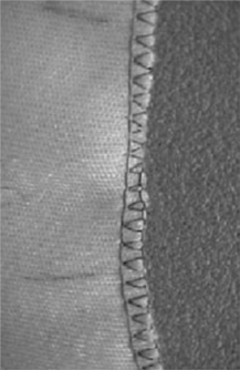
Staggered stitches (Fig. 16.3) can be caused by yarns in the fabric deflecting the needle away from a straight line of stitching, giving a poor appearance. In some hard, woven fabrics, really straight stitching will only be achieved at a slight angle of bias. The causes and solutions for staggered stitches are listed in Table 16.2.
Table 16.2
Causes and solutions for staggered stitches
| Causes of staggered stitches | Possible solution |
| Inappropriate size needle | Go up a needle size |
| Inappropriate needle point | Select sharper point |
| Inappropriate needle blade | Select tapered blade |
| Damaged needle | Replace needle |
| Poor material control | Check current settings |
| Use alternative feed mechanism | |
| Inappropriate seam for selected fabric | Redesign to sew at a slight angle of bias |
Unbalanced stitches in lock stitching can reduce the potential for stretch in a seam in a knitted fabric. Unbalanced seams are often recognised by low extensibility leading to cracking. Bobbin tension should be adjusted until a full bobbin in its case will just slide down the thread when held by the end of the thread. Needle thread tension should also be adjusted to minimise the thread breakage. Where maximum stretch is required in a lockstitch seam, careful adjustments of needle and bobbin thread tension may be needed. Table 16.3 summarises the causes and solutions for unbalanced stitches
Table 16.3
Causes and solutions for unbalanced stitches
| Causes of unbalanced stitches | Possible solution |
| Low extension, bobbin thread breakage | Reduce bobbin thread tension |
| Check needle thread tension | |
| Low extension, needle thread breakage | Reduce needle thread tension |
| Check bobbin thread tension |
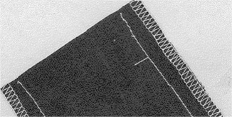
Variable stitch density (Fig. 16.4) may arise from insufficient foot pressure in a drop feed system, causing uneven feeding of the fabric through the machine. It can occur particularly with materials with a sticky or slippery surface. Pressure must be adequate to enable even feeding, but with many fabrics and sewing situations, specialised feed systems are necessary to achieve even feeding of all the plies of the material. Operators may be able to contribute to consistency in stitch density by sewing at a constant speed, rather than in bursts. Table 16.4 summarises the causes and solutions for variable stitch density.
Table 16.4
Causes and solutions for variable stitch density
| Variable stitch density | Possible solution |
| Poor material control using drop feed | Increase foot pressure |
| Check feed dog setting | |
| Avoid sewing bursts | |
| Change to better feeding mechanism foot pressure | |
| Poor material control using specialised feed system | Check feed dog setting |
| Avoid sewing bursts | |
| Change to walking foot mechanism | Introduce puller |
Breakage of thread (Fig. 16.5) and breakage of needle (Fig. 16.6) arises largely as a result of smooth metal surfaces in the machine becoming burred, chipped or damaged and then causing damage to the thread, needle and bobbin or looper. Other causes include improper settings, inadequate maintenance, and poor quality materials. Thread breakage during production is time consuming for the operator, especially if a join in the stitching is not acceptable and he or she must unpick it and start again. Both the cause of the damaged machine parts and the cause of the needle deflection must be investigated. Table 16.5 lists the causes and solutions for thread breakage.
Table 16.5
Causes and solutions for thread breakage
| Thread breakage | Possible solution |
| Damage to thread guiding mechanisms | Polish or replace all damaged parts |
| Damage to throat plate | Polish or replace throat plate |
| Incorrect thread tension | Check and adjust thread tension |
| Incorrect settings for stitch forming | Check timing and adjust |
| Poor thread quality | Change thread |
| Poor cone of thread | Adjust guides, remove faulty cone |
| Wrong needle size for thread | Match thread with needle size |
| Needle overheating | Reduce speed of sewing |
| Reduce needle size | |
| Improve sewability via fabric finish |
16.3.2 Causes and solutions for seam pucker
The visual appearance of the apparel is a principal factor deciding its value. Seam pucker influences the apparel appearance to a considerable degree. It has been well recognised that elimination of seam pucker completely is almost impossible and the common practice is to accept a small amount of pucker. Seam pucker may occur in apparel due to reasons such as structural jamming, differential feed, sewing thread tension, sewing thread shrinkage, fabric shrinkage and mismatched patterns.
General
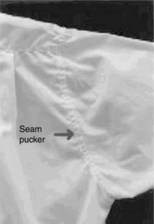
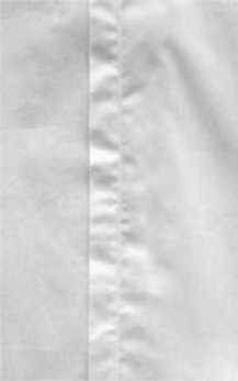
Seam pucker (Fig. 16.7) is a wrinkled appearance along the seam, which influences the apparel appearance to a considerable degree. Seam pucker, identified as a sewability problem about 70 years ago, has been regarded as one of the most important parameters of quality control in apparel manufacturing industries (Anon, 2010; Hati and Das, 2011). It is usually caused by improper selection of sewing parameters and material properties, which results in unevenness on fabrics being stitched together, thus impairing their aesthetic value. In severe cases, seam pucker could appear like a wave front, originating from the seam and extending through the entire garment. In less severe cases, the wave formation is less pronounced, but nevertheless discernible. Indeed, apparel exhibiting pronounced seam puckers is certainly unwelcome by customers. Table 16.6 summarises the causes and solutions for seam pucker.
Table 16.6
Causes and solutions for seam pucker
| Type of pucker | Possible solution |
| Structural jamming | Select finer thread Reduce stitch density Select small needle size Cut and sew on bias Use needle plate with small needle hole Use presser foot with small needle hole |
| Differential feed | Check presser foot and feed dog setting Explore use of PTFE coated feet Use alternative feed mechanism |
| Sewing thread tension | Reduce thread tension Change to thread with reduced extensibility Ensure correct feed timing |
| Sewing thread shrinkage | Select thread with good lubrication Use a synthetic thread or core spun cotton |
| Fabric shrinkage | Refinish fabrics to reduce shrinkage effects Use a synthetic thread or core spun cotton |
| Mismatched patterns | Ensure patterns are correct Ensure cutting is accurate Ensure sewing ease is correct |
Structural jamming
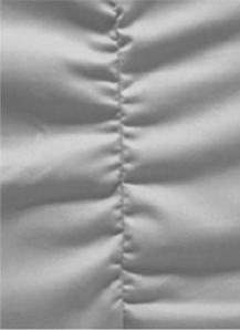
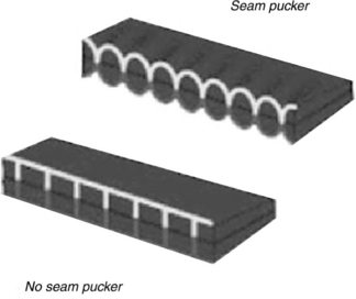
During seam formation, stitches are made by interloping of bobbin and needle thread. These sewing threads displace the fabric yarns from its original position. Fabric yarns attempt to return to original position and they are prevented from doing so by the sewing threads. This causes the fabric layers to displace in a plane perpendicular to fabric plane and results in seam puckering (Fig. 16.8). This kind of pucker is visible mostly in tightly constructed fabrics that do not have enough space to accommodate sewing threads. The problem can be avoided or reduced by using a thinner thread and a small needle point; a needle plate and a presser foot with a smaller needle hole; fewer stitches per unit length; and stitching in a direction which allows the different yarns in the construction of the fabric to be displaced. This kind of pucker is visible on both sides of the fabric (Crum, 1983; Dorkin and Chamberlain, 1961).
Differential feed
Differential feed of the feed dog produces feeding pucker (Fig. 16.9). During sewing operation, bottom layer fabric is moved forwarded by the feed dog positively. But the movement of the top layer fabric is effected through frictional contact between top and bottom fabric. Thus movement to top fabric is not a positive one. The velocity of the top layer fabric is generally lower than that of the bottom layer fabric. This causes accumulation of bottom layer fabrics and produces feeding pucker, which is visible at one side only. Use of an appropriate feed dog, presser foot pressure and sewing speed may help to reduce this kind of pucker (Hati and Das, 2011).
The feed dog should have the optimum number of teeth and rows of teeth for the operation and fabric being sewn. Sometimes, pucker occurs when the material is not held down flat as it is being fed through the machine, creating a rippled appearance as the plies conform to the feed dog teeth. Generally, light weight, wrinkle-resistant fabrics should be sewn with feed dogs having 20–24 teeth per inch. Medium and heavy weight fabrics should be sewn with feed dogs having 14–18 teeth per inch and 8–12 teeth per inch respectively. The pressure exerted by the presser foot against the needle plate causes the fabric to spread. Therefore the dimensions of the seam produced on a fabric have been momentarily altered. When the fabric returns to its normal dimensions, waviness occurs. Reducing the pressure of the presser foot can prevent or at least reduce waviness. High sewing speed requires high presser foot pressure in order to control the feed and prevent the presser foot from bouncing under the impact of the feed dog movement. The bouncing of the pressure foot disturbs the fabric feed, leading to a puckered seam and uncontrolled sewing conditions (Fan and Hunter, 2009).
Sewing thread tension
Tension pucker occurs when the sewing thread is under very high tension (Fig. 16.10). Sewing thread extends due to very high tension, and afterwards attempts to relax. If elastic recovery of thread and shrinkage of fabric coincides, pucker does not occur. But in most situations recovery of thread is more than fabric shrinkage causing fabric to pucker. This is inevitable from the point of view of the sewing operation, which requires higher needle thread tension than bobbin thread tension to snatch the latter for stitch formation. Although sizing or resin on the fabric can prevent or reduce this problem, the seam will still become puckered after laundering. Thread tension pucker can be minimised by reducing the thread tensions on the sewing machine or using a thread with a low elongation or high initial modulus to minimise stretching during sewing. If structural jamming does not occur, it is beneficial to increase the needle size or use a needle with a ball eye to open up a larger hole in the fabric so the stitch can be set. The take-up spring, thread control guides and eyelets should also be properly set to avoid undue tension of the sewing thread during sewing (Fan and Hunter, 2009; Hati and Das, 2011)
Sewing thread shrinkage
High shrinkage potential of fabrics is another source of seam pucker. Threads made of cotton and other natural fibre often shrinks when wet. This may cause seam pucker when fabric shrinkage and thread shrinkage differs. This problem can largely be overcome with the use of synthetic sewing threads. These threads are normally dry heat stabilised to withstand up to 110 °C. They may also cause seam pucker during pressing, if the pressing temperature is above heat-set temperature (Dorkin and Chamberlain, 1961).
Fabric shrinkage
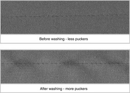
Different shrinkage of plies of fabric causes seam pucker that is visible only after few washing cycles (Fig. 16.11). The component that has the lower shrinkage rate will buckle, resulting in a shrinkage pucker. They will never occur during the sewing operation. They are concerned with dimensional stability of plies of fabric. To prevent or reduce this type of pucker, it is necessary to use compatible components that have similar dimensional stability (Anon, 2010; Hati and Das, 2011)
Mismatched patterns
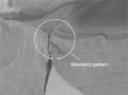
If the patterns of fabric that are to be matched are of unequal length, the experienced tailor will feed more length of the longer pattern. This compensates for extra length, but fabric accumulates in the form of wrinkles and seam pucker appears (Fig. 16.12).
16.4 Causes of damage to the fabric during sewing
Damage to the fabric during sewing can be divided into two categories. One is sewing damage due to thermal problems and the other is due to mechanical problems. Some of the causes of thermal and mechanical problems are discussed here.
16.4.1 Sewing damage due to thermal problems
Needle heating and consequential thermal damage of the material and thread used to stitch-join them have been the issue of numerous comprehensive reports (Dorkin and Chamberlain, 1963; Hurt and Tyler, 1971, 1972a,b; Laing and Webster, 1998; Sondheim, 1953; Worthington, 1975).
Generation and loss of heat in the needle
Heat is generated in the machine needle as a result of friction between the needle passing at high speed through the substrate and the thread passing at high speed through the needle eye. Heat retained by the needle is concentrated in a small mass of metal and the temperature may reach 300–350 °C. During the stitching operation heat is also dissipated from the needle. Heat is transferred by conduction through the needle-bar to other machine parts, to fabric surrounding the needle and to thread in the needle eye. Heat loss by conduction may be higher when materials of high thermal conductivity are used and when the needle size (diameter) is also increased. Conduction is the most important means of heat loss from needles. Movement of air around the needle allows heat loss by convection, with air currents created by moving machine parts and by movement of the sewing thread. Radiation has only a minor role in heat loss from needles. Conduction, convection and radiation are heat-loss processes which occur naturally but, by altering conditions of sewing, heat loss can be increased, though modifications to machine parts may be necessary (Laing and Webster, 1998).
Use of a bulged-eye needle provides for only a single line of contact between needle and material at the needle eye. Using a bulged-eye needle, as compared with a normal needle, results in a drop in needle temperature. Heat loss is also increased by using an air-cooler on the needle. Lubricants applied directly to needles may lower friction between the needle and thread, or they may be applied to thread. Absorption of energy by a vapour spray (i.e. a coolant atomised or directed straight to the needle, with heat being removed by vaporisation of the solvent), offers further scope for temperature reduction. Water may be a satisfactory coolant, but a rust inhibitor is required. Temperature losses achievable in this way can be up to 90 °C.
High needle temperatures and their effects
Few fabrics were damaged seriously by needle heat prior to the 1940s. Since then fabrics and sewing threads manufactured from thermoplastic fibres have become common, and the maximum stitching speed of sewing machines has increased markedly from around 1000 to 6000 stitches/min. Thermoplastic sewing threads, such as nylon and polyester, may be heated by the needle, soften, melt, and break. Nylon and polyester threads melt at 240–260 °C. Cotton and silk are not thermoplastic, but degrade at around 400 °C. Thread breaks decrease production levels because of discontinuity in stitching, assuming that the partly-formed seam is not unpicked and fully restitched (Laing and Webster, 1998).
Softened polymer from either the sewing thread or the fabric being stitched (or both) may be deposited in the needle eye. The needle eye cools when machining stops, and the polymer hardens, thus clogging the eye. On restarting the machine, the sewing thread cannot move though the eye and so breaks. During the down stroke part of the stitch formation cycle a crease may form in the sewing thread at the needle eye. If the needle temperature is sufficiently high, this crease may be set in the thread by heating followed by rapid cooling. Any loop subsequently formed in the sewing thread (required during formation of ISO 301 for example), is improperly shaped when the thread is creased and the rotary hook may not enter the loop. This would result in missed or skipped stitches and seam performance is adversely affected. More generally, any thermal damage to the fabric may affect the properties, performance or appearance of a seam. Table 16.7 summarises the causes and solutions for thermal damage (Carr and Latham, 1994, 2000).
Table 16.7
Causes and solutions for thermal damage
| Thermal damage | Possible solution |
| Excessive sewing speed | Reduce sewing speed |
| Inappropriate needle point | Select sharper set or finer ball point |
| Needle size too large | Reduce needle size |
| Inappropriate fabric density | Ensure fabric density is correct |
| Inadequate fabric finishing | Increase softener content on fabric |
| Inappropriate sewing thread | Select proper sewing thread |
Machine variables affecting needle-heat
Sewing speed has greater influence on needle temperature than any other single factor. Keeping other variables constant, the higher the speed the higher the temperature, up to an equilibrium point for any particular combination of variables. Equilibrium is reached when the heat generated is equal to that lost by conduction, convection and radiation. The actual temperature at equilibrium is specific to stitching conditions, for example the number of fabric plies, fabric properties, needle size and thread type. The time and number of stitches formed before the equilibrium may be quite short (Laing and Webster, 1998).
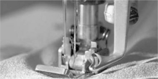
Needle size (Fig. 16.13) has been identified as an important variable. With lower temperatures typical of fine needles, less work is required for penetration of the cloth. Where needle diameter is larger, greater force is required for penetration of cloth and higher temperatures are observed. Needle temperature increases with increasing needle size but the magnitude of the effect is small, other variables being more significant (Hurt and Tyler, 1971, 1972b).
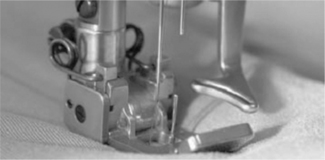
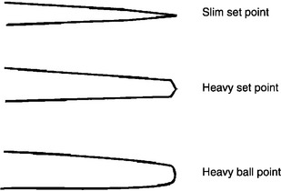
Needle-point shape (Fig. 16.14) and surface finish are also significant variables. Sewing with a heavy-ball needle usually results in temperatures at the higher end of the range. Bulged-eye needles operate at lower equilibrium temperatures than cloth or set point needles, the reduction being 11–30 °C. The surface finish of the needle also affects generation of heat. The highest temperatures are with dark matt surface needles, nickel, plain steel and chrome finishes giving progressively lower temperatures. The main parts in contact with material being stitched, the top of the blade and the needle point appear to have most effect on heat generated.
Any form of restraint on the movement of fibre and yarns in fabric might be expected to lead to an increase in the force required for the needle to penetrate the fabric. Machine parts such as the presser foot and throat plate affect the extent to which fabric is restrained. With respect to the throat plate, its hole size appears to be a critical variable. Movement of the fabric during the stitching operation is three dimensional with a glove of yarns/fibres forming around the needle as it passes down through the throat plate. If the throat plate hole is too small the fabric cannot be depressed and yarns are displaced temporarily. This may cause some fibres in the yarn to break. It has been shown that increasing the diameter of the throat plate hole decreases the equilibrium needle temperature (Laing and Webster, 1998).
Material variables affecting needle-heat
Needle heat generated during stitching depends on fabric-needle surface characteristics, fabric frictional characteristics, and fabric tightness (Laing and Webster, 1998).
Fabric density is a critical determinant of needle temperature. Any reduction in the ease with which fibre and/or yarns can be deflected from the path of the needle increases the force required for needle penetration. For example, woven fabrics with high cover factor and knitted fabric constructed of short stitches will be associated with elevated needle temperatures (Hurt and Tyler, 1971, 1972b; Laing and Webster, 1998).
Fabric finishing treatments (cleaning processes and solvents used to extract fats/waxes from the cloth, dyeing for colour change, resin finishes used to impart a different hand to cloth or to alter creasing characteristics) because of their effect on the frictional properties of the fabric, are the most important material variable influencing thermal damage. The amount and type of finish determines whether the needle temperature is raised or lowered. A decrease in needle temperature occurs with addition of lubricants or softeners – commonly long-chain fatty acid radicals that are hydrophilic. Softeners are applied primarily to improve the handle of fabric, but simultaneously may improve its sewing characteristics. Some softener is transferred from the fabric to the needle, the needle thus being lubricated, which reduces the friction thereby lowering equilibrium needle temperature. Fibres and yarns are stiffened by the application of many forms of resin and the handle and some other properties of the finished fabric are usually altered. These effects increase the resistance of yarns and fibres to movement by the needle, resulting in higher frictional forces and equilibrium needle temperatures (Hurt and Tyler, 1971; Laing and Webster, 1998).
The influence of sewing thread on needle temperatures is complex. Thread is able to cool the needle by conducting heat away (transfer occurring between the hot needle and the cold thread) and by increasing convective losses due to the cooling air stream created by the moving thread. The influence of both effects is greatest at the eye of the needle. Heat is also generated by the thread passing rapidly through the eye of the needle and against machine parts. Equilibrium needle temperature in a test run without sewing thread was lower than that obtained when subsequently stitching with a thread. A needle carrying thread, but without interacting with any fabric, heats by about 50 °C when running at high speed (Hurt and Tyler, 1971, 1972b; Laing and Webster, 1998).
The type of thread appears to affect the equilibrium needle temperature. Continuous filament thread results in higher needle temperatures than staple fibre thread. With continuous filaments, there is a greater area of contact between the thread and needle, and in addition less air is carried along with the thread on account of its smooth surface. Sewing threads of bulked or textured yarns have both a reduced surface area for contact between thread and needle, and facilitate air movement through the needle eye. Staple sewing threads also transport more cooling air to the needle, allowing the sewing speed to be increased by up to 10%, relative to that with comparable continuous filament thread, without adverse needle-temperature effects (Dorkin and Chamberlain, 1961; Laing and Webster, 1998).
16.4.2 Sewing damage due to mechanical problems
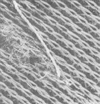
During stitch formation the cloth may be damaged mechanically rather than thermally. When the damage is characterised by fragmented or broken fibres, filaments or yarns, it is referred to as mechanical damage. Such damage may be apparent immediately after stitching but frequently will not appear until after the product has been used, when seams have been subjected to some form of tension, stress, strain, deformation or after successive cleaning. In a woven fabric, damage of this sort may be masked by the sewing thread, whereas in knitted structures the visual effects of mechanical damage are more severe (Fig. 16.15). Fabric breakdown may extend well beyond the area adjacent to the seam. Seams damaged in this way are unacceptable from the perspective of both aesthetics and performance. Table 16.8 summarises the causes and solutions for mechanical damage (Carr and Latham, 1994, 2000).
Table 16.8
Causes and solutions for mechanical damage
| Mechanical damage | Possible solution |
| Needle size too large | Reduce needle size |
| Inadequate fabric finishing | Increase softener content on fabric |
| Inappropriate needle point | Select sharper set or finer ball point |
| Damaged needle point and throat plate | Replace damaged parts |
| Mismatch between needle size and throat plate hole | Reduce tightness of fit |
The damage process
Inclusion of a seam in fabric generally reduces the fabric breaking load. Mechanical damage of yarns adjacent to the stitching may be a contributing factor. Rapid rupture of a yarn during stitching may occur as a result of extension to its breaking extension, or by cutting. The needle or the sewing threads may cut through the yarns of the material, but the mechanical damage outlined below appears largely independent of the presence of sewing threads.
When the needle point strikes a spun and/or multi-filament yarn and passes through its centre, a diamond-shaped opening is formed and some fibres/filaments are extended to accommodate the thickness of the needle. Twist will be displaced. Where the yarn has a low twist, fibres/filaments can move easily, but as twist level increases, twist displacement become increasingly problematic. fibre/filament failure will occur if the fibres are stretched to their breaking extension (Laing and Webster, 1998).
Many fabrics, especially those made from cotton and/or viscose, are treated with a stiffener, starch or crease-resistant resin finish. With the addition of starches and dextrins, the extensibility of individual fibres may not be affected but the fibres adhere to one another laterally. Adhesion prevents fibres slipping. With a resin finish, the extensibility of the fibres generally decreases. The effect of any finishing agent depends on the yarn’s initial twist level, with low-twist yarns not being adversely affected by more severe finishing processes.
Interstitial spaces in the fabric, sufficient to accommodate a needle or to facilitate yarn redistribution, are necessary if mechanical damage is to be avoided. If the fabric (woven or knitted) has a high cover, yarn relocation is impeded. With needle penetration of a fabric with maximum cover, the fabric tends to buckle from the horizontal plane. As a result warp/weft yarns in a woven fabric are pushed together, and where the fabric is near its maximum cover, this is possible only if the fabric buckles from the horizontal plane. The action of the presser foot and the throat plate tend to inhibit buckling, and yarn breakages may result. Damage to knitted fabrics needs also to be considered as a three dimensional phenomenon. Yarns are stretched in the plane of the fabric with yarn robbing, and also stretched in the direction of the needle axis with deformation of the fabric by the needle point. In some fabrics, the length of yarn in a knitted loop is less than the circumference of the needle, so yarn robbing from adjacent loops occurs. The case with which any one loop can draw from adjacent loops is critical. Two separate frictional forces are in operation: that generated between the needle surface and the yarn around it: and that generated as the yarns in the fabric move over each other changing their configuration to accommodate the needle. As yarns are forced out of the path of the needle, they are stretched. If the extension forces are equal to or exceed the breaking load of the yarn, it will break and result in a hole in the fabric at the seam (Laing and Webster, 1998).
Fabric is controlled in a horizontal plane during stitching by the feed dog and the spring-loaded presser foot. The needle acts vertically on the cloth and filaments/yarns may form a glove around the needle point. Yarns may be forced into the throat plate hole. With knitted fabric, only those loops or parts of loops not held by the presser foot are free to move. Cotton interlock, which is often badly damaged in machine sewing, is not damaged at all if the fabric is held freely in the hand and hand stitched, thus illustrating the detrimental effect of clamping.
16.5 Control of fusing and pressing operations, storage and packaging
The following section discusses the process control issues relating to fusing and pressing operations, storage and packaging.
16.5.1 Fusing operations
Using fusible interlinings can prevent or reduce the problems of seam pucker. A fusible interlining is defined as a base fabric having a deposit of thermoplastic adhesive resin that can be bonded to another fabric by the application of heat and pressure (Cooklin, 1990). Fusible interlining enabled the apparel industry to make great strides in efficiency and quality in the past several decades, but the matter of finding the right interlining for a specific shell fabric continues to present challenges. If fusing is not handled properly, the shell fabric can change in colour or surface appearance, shrink, stretch or stiffen (Fan and Hunter, 2009).
To ensure good appearance and drape of the finished garment, the interlining should be compatible with the shell fabric. However, fusible interlinings vary in terms of base fabric composition, base fabric structure, and type of adhesive and finish. Fusible interlining suppliers are numerous. It is not an easy task to select the most suitable fusible interlining for a specific shell fabric or a specific range of shell fabrics. In general, most companies have guidelines on how to select fusible interlinings. The traditional method of choosing a suitable interlining fabric is by trial and error and/or by past experience. In general, many problems in fusible interlining selection and use can be avoided if manufacturers collaborate with their interlining suppliers in choosing the right fusible and conduct pre-production testing to ensure consistent performance
Strike-through and strike-back
During fusing, three parameters must be considered: the fusing method; the fusing machine; and the condition of the fusing (viz. temperature, time pressure and cooling). If the parameters are not properly selected and/ or adjusted fusing problems (e.g. strike-through and strike-back, colour changes and fusing distortion) can occur. Strike-through means that the adhesive resin appears on the outside of the fabric being fused. Table 16.9 summarises the causes and solutions for strike-through. Strike-back means that adhesive resin appears on the non-adhesive side of the fusible interlining after fusing. Table 16.10 lists the causes and solution of strike-back (Anon, 2010; Fan and Hunter, 2009; Galuszynski and Robinson 1986).
Table 16.9
Causes and solutions for strike-through
| Causes | Solution |
| Too long fusing time | Reduce fusing time. Shorten fusing time for thinner fabrics. Carry out a fusing test before bulkproduction. |
| Too high fusing temperature | Reduce fusing temperature. Carry out a fusing test before bulkproduction. Use a temperature measurement strip to find the optimum fusing temperature. |
| Too high fusing pressure | Fusing test should be carried out to check for the bond, surface and handle of fabrics before bulk production. Pressure setting should follow machine manufacturer’s instructions. Reduce the pressure for lightweight and loosely constructed outer fabrics. |
| Incompatible fusible interlining (toomuch adhesive on interlining) | Avoid using interlining with excessive adhesive. Reduce size of the adhesive dots on the interlining. Reduce the weight of the adhesive dots on the interlining. Carry out a fusing test before bulk production. |
| Inappropriate fusing method for thinand loosely constructed fabrics | Use frame fusing for thin and loosely constructed fabrics. Carry out a fusing test before bulk production. |
Table 16.10
Causes and solutions for strike-back
| Causes | Solutions |
| In appropriate fusible interlining | Avoid using too light substrate materials.Avoid using interlining with excessive adhesive.Reduce size of the adhesive dots on the interlining.Carry out a fusing test before bulk production. |
| Too long fusing time | Reduce fusing time.Carry out a fusing test before bulk production. |
| Too high fusing temperature | Reduce fusing temperature to avoid adhesive becoming too fluid.Carry out a fusing test before bulk production.Use a temperature measurement strip to fi nd theoptimum fusing temperature. |
| Too high fusing pressure | Fusing test should be carried out to check thebond, surface and handle of fabrics before bulkproduction.Pressure setting should follow machinemanufacturers’ instructions.Reduce the pressure for lightweight and looselyconstructed outer fabrics |
Colour changes during fusing
Inappropriate fusing can cause temporary or permanent colour changes (shine/glazing and/or discolouration) in fabrics. Colour changes during fusing are caused by the action of heat on certain dyes. The causes and solutions for this phenomenon are listed in Table 16.11 (Anon, 2010; Fan and Hunter, 2009; Galuszynski and Robinson 1986).
Table 16.11
Causes and solutions for colour changes during fusing
| Causes | Solutions |
| Some synthetic fabrics change colour temporarily after heat press/iron heat | Regulate the pressing temperature, pressure and time to avoid overheating and over pressing.Allow fused fabrics to cool down for a while to regain their colour. |
| Excessive temperature, pressure colour during the fusing process | Put a cloth (same material or cotton) to cover the fusing material during heat pressing.Select multivariable adhesive (MVA) that requires lower temperature, pressure and time for fusing. |
Fusing distortion
Fusing distortion means that panels are distorted during the fusing process. This problem should be prevented, as such distorted panels cannot be corrected and must be discarded as waste. Fusing distortion may be caused by inadequate fusing conditions, improper handling of fusing panels, poor stability of the fabric and wrong fusing directions. The cause and solutions of fusing distortion are summarised in Table 16.12 (Anon, 2010; Fan and Hunter, 2009; Galuszynski and Robinson 1986).
Table 16.12
Causes and solutions for fusing distortion
| Causes | Solutions |
| Poor fusing machine setting and conditions, e.g. speed of the continuous fusing press, temperature, pressure and setting time | Reduce the speed of the fusing press.Reduce the pressure of the fusing press.Establish optimum fusing machine setting by consulting the interlining supplier.Allow time for the fused parts to cool before handling.Test the fusing conditions before bulk fusing. |
| Bad orientation of fusing panels | Change orientation of panels in order to avoid the corner of the garment panels being caught fi rst by the pressure rollers of the fusing press.Pre-set the fusing panels by hand-ironing before passing the fusing panels to the fusing press.Use flatbed fusing press, if available. |
| Unstable fabric/substrate properties | Use stable fabrics-avoid fabrics which have low shear rigidity.Take extra care in fabric handling during the fusing process. |
| Wrong fusing direction | Interlining and outer fabrics should be fused in the same direction, with similar dimensional changes. |
16.5.2 Pressing operations
Pressing often represents the final opportunity to enhance apparel shape, and to smooth or flatten creases in the apparel. Good pressing can also help to preserve the shape and fit of apparel. Pressing performance can govern the appearance of a garment, as presented to a potential customer. Well-pressed apparel makes a good impression on potential customers, and can command a higher price. Good pressing appearance gives an overall smooth and undisturbed appearance without any shine, scorching, melting, clamp marks or water marks. There should be no unplanned creases or pleats, pressed wrinkles, or hems pressed on the wrong side. Seams and side seams of pants and shorts should be pressed seam-on-seam with a smooth centre crease (Brown and Rice, 2001; Fan and Hunter, 2009). Fabrics should be engineered to have optimum pressing performance, and apparel should be pressed under the proper pressing conditions.
Preparation and handling
Before pressing, remove all the tacking threads and pins so as to avoid any marks on the garment. In order to prevent scorching, melting, hardening or shrivelling, first test the heat (temperature) of the iron prior to pressing so as to ensure that it is suitable for the garment to be pressed. Test the heat on a spare piece of the actual fabric before applying the iron to the apparel, so that a suitable heat can be found. When placing a garment onto a pressing machine, make sure the grain of the fabric is not pulled out of line, so as to ensure that it is not unnecessarily creased. Keep all seams in a straight line. To avoid shine or iron marking on the right side, press on the wrong side of the apparel. If necessary, slip a strip of paper underneath seam turnings to prevent their marking the right side of the fabric or apparel (Butler 1972; Fan and Hunter, 2009).
Pressing conditions
In practice, pressing can be conducted either with industrial or domestic irons (with or without steam) or else with a heavy press. Whatever the pressing method chosen, pressing consists of five components namely, heat (temperature), moisture (usually as steam), pressure, time and equipment. When pressing low-volume, high-fashion or highly structured apparel, an industrial flat iron is usually used, similar to those used by the consumers at home. For pressing performed on high-volume, ready-to-wear apparel, presses or pressing machines, such as flatbed, buck presses, form presses and upright presses are normally used, these being more efficient than hand pressing. Generally, the apparel is slipped over the machine; steam and pressure are applied automatically and then a vacuum extracts any excess moisture. Ideal pressing conditions vary for different types of fabrics and apparel (Brown and Rice, 2001; Fan and Hunter, 2009; Crowley, 1978).
Effect of fabric properties on pressing performance
Different fabrics have different properties, which require different pressing conditions. For example, microfibre apparel has poor resistance to heat and can be hard to press and finish without any shine, marks or glazes. In order to solve this problem, it is recommended that apparel comprising microfibres or extremely light fabrics be pressed from inside using foam finishes. If they need to be pressed from the 'right side' of the fabric, the temperature has to be very low, whilst the steam has to be perfectly dry since synthetic cannot take any moisture. The press duration and ambient relative humidity for both preconditioning and post conditioning of the fabrics also has a significant influence on the pressing performance (Fan and Hunter, 2009).
16.5.3 Storage and packaging
After pressing, the garment should be free from wrinkle and creases, and have a good shape. Apparel needs to be stored and packed for delivery to the potential customers. Nowadays, there are manual or semi-automatic packaging machines available in the industry, but careless or inappropriate storage and packaging will cause a deterioration in the appearance of the final product.
The pressed apparel should be stored in a cool, dry place. The storage should have sufficient room to accommodate the apparel without being too closely packed, which could not only cause wrinkles in the apparel, but also block the air circulation (causing a moisture build-up leading to mildew on the apparels), or result in excessive heat causing the plastic bags to bond to the fabric. Also, the storage area should be as clean as possible so that dust and dirt, the acid pressure in atmospheric pollution, as well as the presence of moths or other pests, do not cause apparel to deteriorate during storage. Apparel in storage should not be subjected to any strain or movement that could cause the fibres to become weak and break. Avoid pressing in sharp folds. Different types of apparel should have different conditions of storage and packaging. Knitted or stretched apparel should preferably be folded rather than hung, and should be stored in a plastic bag. Nylon hosiery should be stored and packed in plastic bags to prevent snagging. Sweaters should also be stored in plastic bags to keep them from becoming contaminated by lint. Clothing containing wool should be stored in a moth-free or mothproofed place (Finch and Putnam, 1977; Fan and Hunter, 2009).
Vacuum packing is recommended for tailored jackets; this not only reduces the storage space required for the packed apparel, but also prevents reintroducing creases during storage and transportation. This packing is also reusable, which can reduce environmental pollution. Vacuum packaging is now commonly used in households, and available in different sizes for different kinds of apparel. Vacuum packing also saves space, and protects the apparel against dirt, moisture and insects (because it is waterproof and airtight) (Fan and Hunter, 2009).
16.6 Quality evaluation of apparel: testing for tailorability
The following section discusses in general the relationship between tailorability and low stress mechanical properties. Evaluation of low stress mechanical properties using KES (Kawabata Evaluation System) and FAST (Fabric assurance by simple testing) instruments are also discussed.
16.6.1 Tailorability and low-stress mechanical properties
Low-stress mechanical properties of fabrics have established themselves as an objective measure of quality and performance. There are two major reasons why they are important in tailoring:
• Fabrics are more extensible in the low-load region than in the higher-load region.
• The property in this region is closely related to the tailoring process and the comfort of a wearer.
In the tailoring process, an initially flat fabric is formed into stable, complex, three dimensional apparel shapes. The conformation of a flat fabric to any three dimensional surface requires complex mechanical deformation of the fabric, such as bending, extension, longitudinal compression and shearing in the fabric plane at very low loads. Apparel patterns often require different lengths of fabrics to be sewn together by overfeeding the longer of the two fabrics to form an intermediate length as a means of imparting a three dimensional character to the apparel. The seam is inserted either in the warp or weft direction or at some angle. Higher fabric extensibility in the initial region causes difficulty in the handling of fabrics during the cutting and sewing processes. Thus the fabric tensile, longitudinal compressional and shear properties are the main mechanical properties relevant to tailoring (Kothari, 1999a).
Fabric mechanical properties are measured under low loads so that conditions similar to the actual fabric deformation in production and use of apparels are taken. The hysteresis behaviour in tensile, shear, bending and compression is measured to determine the fabric resilience. The fabric surface properties are also measured to detect roughness by human senses. Test systems such as KES (Kawabata Evaluation System) and FAST (fabric assurance by simple testing) were developed for conducting tests on fabric samples in the low-stress region.
16.6.2 Kawabata evaluation system
Kawabata, in order to establish the relationship between subjectively assessed hand values and properties of fabrics, have identified certain properties such as tensile and shear, bending, compressional and surface frictional characteristics. These properties were considered as important from the point of view of fabric handle. In each group certain characteristic values have been identified that can represent the property and can be used for establishing interrelationships between fabric hand and these properties. A total of 16 such parameters given in Table 16.13 have been identified. Kawabata Evaluation System of Fabric (KES-F) has four modules for measuring low stress and surface characteristic of fabrics (Apurba Das and Alagirusamy, 2010; Kawabatta, 1980).
Table 16.13
The sixteen parameters describing fabric properties
| Parameter | Symbol | Description |
| Tensile | LT | Linearity of load extension curve |
| WT | Tensile energy (gf.cm/cm2) | |
| RT | Tensile resilience (%) | |
| Shear | G | Shear rigidity (gf. cm/degree) |
| 2HG | Hysteresis of shear force at 0.5 degree shear angle | |
| 2HG5 | Hysteresis of shear force at 5 degree shear angle | |
| Bending | B | Bending rigidity (gf.cm2/cm) |
| 2HB | Hysteresis of bending moment (gf.cm/cm) | |
| Compression | LC | Linearity of compression-thickness curve |
| WC | Compressional energy (gf.cm/cm2) | |
| RC | Compressional resilience (%) | |
| Surface | MIU | Coefficient of friction |
| MMD | Mean deviation of MIU | |
| SMD | Geometrical roughness (|im) | |
| Fabric construction | W | Fabric weight per unit area (mg/cm2) |
| T | Fabric thickness (mm) |
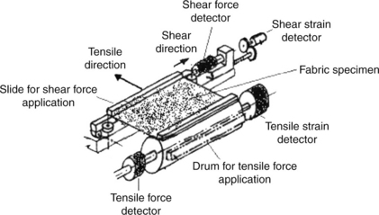
KES-F1 (tensile and shear tester)
The principle of KESF-1 system is shown in Fig 16.16. The fabric specimen is clamped between two jaws (one attached with drum for tensile force application, and the other attached with slide for shear force application) and subjected to a constant tension of 10 gf/cm by a weight attached to the drum on which one jaw is mounted. Tensile force is applied by allowing the drum to rotate freely. The tensile force is measured by the tensile force detector by measuring the torque and the tensile strain is measured by tensile strain detector from the data of rotational angle of the drum. The shear force is measured by a transducer connected to the other jaw (attached with slide) which moves sideways to apply shear deformation. The shear force is measured by the shear force detector by measuring the force required to slide, and the shear strain is measured by shear strain detector from the resulting displacement of the slide.
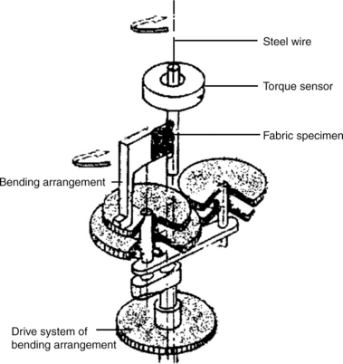
KES-F2 (bending tester)
The principle of the KESF-2 system is shown in Fig. 16.17. The fabric specimen is gripped by two jaws. One jaw is attached with the bending arrangement, which moves in a circular direction to apply bending force. The other jaw is connected with the torque sensor, which detects the torque value of steel wire during bending of specimen. The curvature of bending is obtained from the drive to the bending arrangement. The fabric specimen is bent with the help of bending arrangement between the curvatures of − 2.5 cm− 1 and + 2.5 cm− 1.
KES-F3 (compression tester)
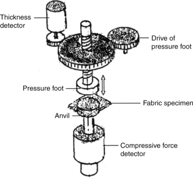
The working principle of KESF-3 system is shown in Fig. 16.18. The fabric specimen is compressed between two plates, that is anvil and pressure foot. The fabric specimen is placed on the anvil and pressure is increased with the help of the pressure foot, while continuously monitoring the sample thickness with a thickness detector. The compressive pressure is detected by the compressive force detector. The pressure foot is driven from the drive arrangement.
KES-F4 (surface tester)
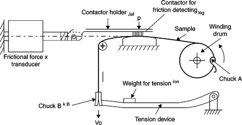
Friction and surface roughness characteristics of fabrics are measured by KESF-4 system. The working principle is shown in Fig. 16.19, where the surface roughness and surface friction of the fabric specimen are being measured at the same time. The fabric specimen, kept at constant tension by a hanging dead weight, gets to-and-fro motion from a drum that rotates intermittently clockwise and anticlockwise. The frictional force between the fabric specimen and the friction surface at the friction point is detected by a frictional force detector. The surface roughness of the fabric is measured by a detection system that is basically a displacement sensor. The probe of the displacement sensor is in touch with the fabric surface. When the fabric moves in the horizontal plane, due to the surface roughness the probe is deflected vertically. This vertical deflection of the probe measures of the surface roughness of fabric.
From all the above parameters, which are obtained from KESF instruments, the total handle value (THV) can be calculated, which is the indicator of fabric handle behaviour of fabric.
16.6.3 Fabric assurance by simple testing (FAST)
The FAST system has been developed by CSIRO (Australia) primarily for quality control and assurance of fabrics. It measures properties that are closely related to the ease of apparel manufacturing, handle characteristics and the durability of surface finishing. Unlike the KES system, FAST measures only the resistance of fabric to deformation and not its recovery from deformation. However, the FAST system is inexpensive, simple to use and robust in construction. It consists of a series of three instruments and a test method (Apurba Das and Alagirusamy, 2010; Kothari 1999c).
FAST-1 (compression meter)
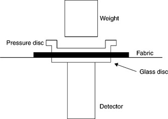
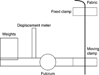
A schematic diagram of FAST-1 system is shown in Fig. 16.20. It measures the fabric thickness over a range of loads, the variability and the durability of the thickness of the fabric surface layer. It can measure fabric thickness to micrometre resolution at two predetermined loads, and thereby enables the accurate measurement of surface layer thickness. The fabric thickness (T) is measured at a pressure of 2 gf/cm2. Surface thickness (ST) is the difference in thickness of a fabric measured at pressures of 2 and 100 gf/cm2.This gives information about the hairiness or surface bulk of the fabric (closely related to surface treatment like brushing, singeing, finishing etc). Released surface thickness (STR) is the measure of the ST after the fabric is exposed to steam or water. The increase in fabric ST obtained by this steaming process simulates the actual change in surface characteristics that occur during actual use of the apparel.
FAST-2 (bending meter)
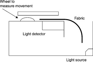
A schematic diagram of the FAST-2 system is shown in Fig. 16.21. FAST-2 measures the bending length (BL) and bending rigidity (B) of fabric. The fabric BL simulates the draping behaviour of fabric and B is related to the quality of stiffness when a fabric is handled. B is particularly crucial in the tailoring of lightweight fabrics as a very flexible fabric (low B) may cause seam puckering while a high B fabric can be more manageable in sewing and so produce a flat seam. Operator error in aligning the sample is eliminated with the use of an optical sensor. BL is displayed automatically, so chances of the error due to the operator's judgement are eliminated.
FAST-3 (extension meter)
A schematic diagram of the FAST-3 system is shown in Fig. 16.22. It measures extensibility of fabric at various loads as well as its shear rigidity. It is capable of measuring the fabric extensibility in warp, weft and bias directions over a range of loads, with direct reading of extension as a percentage of the initial gauge length. The fabric extension is displayed as a percentage with a 0.1% resolution. Extensibility is measured at three loads 5 gf/cm (E5), 20 gf/cm (E20) and 100 gf/cm (E100). The difference between fabric extensibilities at between E5 and E20 is used to calculate fabric formability (F), which is a parameter related to the incidence of seam pucker. Fabric extensibility is combined with bending rigidity to calculate F, which is a measure of the ability of a fabric to absorb compression in its own plane without buckling. E100 is used in FAST control chart (FAST fabric fingerprint) as the measure of fabric extensibility. If the value is below approximately 2%, then the fabric will be difficult to extend during seam overfeed. Apart from the fabric extensibility, another important fabric handle related parameter, shear rigidity (G), is measured in the FAST-3 system. The bias extension is converted to G, which is directly related to fabric looseness. For G below 30 N/m, the fabric deforms so easily that it may give problems in handling, laying up and sewing. Conversely if it is above 80 N/m then the fabric can be difficult to overfeed, mould, etc.
FAST-4 (dimensional stability test method)
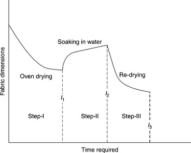
Poor dimensional stability of fabrics is one of the main causes of poor appearance in apparel. This is a test method for measurement of relaxation shrinkage (RS) and hygral expansion (HE), which can test these parameters in less than an hour as compared to the conventional one-day test. The drying is done in a forced convection oven. A template and a ruler are the only equipment required to do the test. The results from this method simulates the change in fabric dimensions that may occur during the actual wear as the fabric is subjected to washing and changing humidity conditions. RS is mainly due to the recovery of fabric structure that became strained during manufacturing, while HE (and hygral contraction) is caused by the swelling or de-swelling of hygroscopic fibres. Very high RS results in the problem of change of size, puckering, etc. Similarly, higher HE may result in seam pucker, fabric waviness, buckling and overall poor appearance.
The testing is completed in following three difference steps (Fig. 16.23):
• Step-I: The fabric specimen is first over dried (0% moisture) to measure its dry dimensions (l1).
• Step-II: It is then soaked in water to measure its wet relaxed dimensions (l2).
• Step-III: The specimen is dried again to measure its final dry dimensions (l3).
RS and HE are calculated from the above dimensions, using following relationships:
The FAST data analysis software, included as part of the FAST system package, automatically plots the appropriate values and joins the various plotted points together to form a fabric 'FAST control chart', which is unique to each particular fabric. Figure 16.24 shows a typical FAST control chart. Each value has a separate scale showing a graphical representation of the range of values in the appropriate units that we expect for each of the various measurements. For example relaxation shrinkage 'RS-1' represents the warp value and 'RS-2' that of the weft. In addition to the values for the various measurements, each scale contains one or more shaded zones. If the fingerprint falls into one of these zones, a potential problem with the particular aspect(s) of fabric performance influenced by that property is indicated.
16.7 Quality evaluation of apparel: testing for sewability
Sewability is defined as the ability and ease with which fabric components can be quantitatively and qualitatively seamed together to convert a two dimensional fabric into three dimensional apparel. The quality and serviceability of a garment not only depends on the quality of the fabric, but also on the quality of the seam. Quality characteristics of the seam can be measured by seam parameters such as seam strength, seam slippage, seam damage or needle cutting and seam appearance (Kothari, 1999a).
16.7.1 Seam strength
Seam failure in apparel can occur because of either the failure of the sewing thread, leaving the fabric intact, or fabric rupture, leaving the seam intact or both breaking at the same time. Seam strength in woven and knit fabrics is tested in almost the same manner as fabric breaking and bursting strength respectively. A specimen 11 x 10 cm2 is placed between two sets of jaws, 7.6 cm apart in such a way that the seam is in the middle of the 7.6 cm distance. These jaws are then pulled away from each other creating a tensile force on the specimen, ultimately resulting in a break. The force, elongation and nature of the break (seam break or fabric rupture) are noted [ASTM D1683]. In the case of a knitted specimen, the specimen is clamped in the ball burst tester in such a way that the seam is in the middle of the clamps. The force is exerted against the specimen by the steel ball, until rupture occurs.
The strength of a seam or stitching should equal that of the material it joins in order to have a balanced construction that will withstand the forces encountered in the use of the apparel of which the seam is a part. The stitch type, thread strength, stitches per inch, thread tension, seam type, and seam efficiency of the material affect the seam strength.
Generally, a seam made with chain stitch will be stronger than a seam made using lock stitch. Obviously, stronger the sewing thread, the stronger the seam. A higher number of stitches per centimetre, up to a point, will give higher seam strength, but too many stitches will weaken the fabric, so that the seam may stay intact but the fabric may rupture resulting in seam failure. Higher thread tension will give higher seam strength but too high a thread tension will result in seam puckering. Lap felled seams will be stronger than lapped seams. Fabric with higher seam efficiency will provide stronger seams than fabric with lower seam efficiency. Seam efficiency is seam strength expressed as a percentage of fabric breaking strength. The elasticity of a seam or stitching should be slightly greater than that of the material that it joins, so that the material will support its share of the forces encountered in the end use of the apparel. The elasticity of a seam or stitching depends on the stitch type and thread elasticity.
16.7.2 Seam slippage
In some apparel, before seam failure occurs, enough yarn slippage (filling yarns shifting over warp yarns or vice versa) develops to render the apparel unusable, because such failure is not readily repairable by seaming. Seam slippage is measured by subtracting the elongation of the fabric from the elongation of the fabric with a seam in it. The difference is indicated as seam slippage, which can be considered one form of failure of seam assembly [ASTM D434 and D1683].
16.7.3 Seam damage or needle cutting
Seam damage or needle cutting in the fabric is objectionable because it may result in reduced seam strength or poor appearance or both due to frayed yarns. To find the needle cutting index, sewing threads are removed from specimens. The count of the number of fabric yarns and the count of the number of severed and fused fabric yarns in the direction nearly perpendicular to the direction of sewing thread are used.
Seam damage or needle cutting occurs due to stiffness of the yarns in fabric and their lack of mobility. Instead of moving and deforming when the needle penetrates the fabric structure, the yarns remain taut and are ruptured or burned. Also some damage may occur due to excessive heat generated due to friction of the sewing needle and fabric.
16.7.4 Seam appearance
The overall seam performance can be best judged by examining surface look of the seam line with a microscope. Although this method is quite subjective and needs expertise to predict the performance, it can however identify various aspects of seam appearance. The microscopic study helps in examining seam and surface damage.
16.8 Quality evaluation of accessories
Accessories add value to the apparel, hence the quality evaluation of accessories is very important. The following section discusses the quality evaluation of accessories such as zippers, sewing threads, buttons and snap fasteners.
16.8.1 Zippers
Zippers can be tested using any one or more of the following test methods (Kothari, 1999b; Pradip and Satish, 1998).
Durability of finish of zippers to laundering
The durability of the finish of zippers to laundering is evaluated by laundering the test specimen in a Launderometer (AATCC test method 61).
The effect of the test on the zipper coating is evaluated by noting the loss of coating on the zipper chain or components or both (ASTM D2051).
Colourfastness of zippers to dry-cleaning, light and crocking
The colourfastness of a zipper to dry-cleaning is tested by subjecting the zipper stringer (tape) to commercial dry-cleaning with a multifibre fabric. The dry-cleaned specimen is compared with the original specimen and any change in the colour of the specimen or staining of the multifibre fabric is then assessed using the AATCC gray scale for colour change or the chromatic transference scale. The colourfastness of zippers to light and crocking is tested in the same way as the colourfastness of fabrics to light and crocking (ASTM D2052, ASTM D2053 and ASTM D2054).
Colourfastness of zippers to laundering
The colourfastness of zippers to laundering is tested by subjecting the zipper with a multifibre test fabric to home laundering according to the intended care instructions for the apparel on which this particular zipper would be used. The alteration in shade of the zipper stringer (tape) and the degree of staining of the multifibre test fabric are evaluated by the AATCC gray scale for staining and colour change or the chromatic colour transference scale (ASTM D2057).
Durability of finish of zippers to dry-cleaning
The durability of the finish of zippers to dry-cleaning is tested by subjecting the zipper to dry-cleaning, as in AATCC test method 86, but the zipper is air-dried rather than hot-pressed. The specimen is then evaluated visually for any exposed base metal compared to a new zipper or compared to a sample illustrating an acceptable degree of coating loss (ASTMD 2058).
Resistance of zippers to salt spray
Sometimes, due to corrosion, a zipper will not operate smoothly and its crosswise strength may be reduced. Such deterioration in a zipper can be evaluated by subjecting the zipper to a salt spray test. Of course, plastic/ nylon zippers do not corrode, and therefore, this test applies only to metal zippers. In this test method (ASTM D2059), specimens are subjected to salt spray (5% salt solution at 33 °C to 36 °C) for 24 h continuously. The exposed specimens are then visually evaluated for any sign of corrosion and tested for case of operation and crosswise strength, and the results are compared with the case of operation and crosswise strength of the original specimens (ASTM D2059).
Operability of zippers
The operability of zippers is tested by pulling the slider with a force indicator (such as a pull gauge) along the zipper chain alternately in the opening and closing directions and recording the force required to maintain each movement. This force is a measure of the case with which the zipper will operate in end-use applications (ASTM D2062).
Strength tests of zippers
The usefulness of a zipper in service can be evaluated by the following strength tests. No test determines the suitability of a zipper for a specific end use. Since the tests are interrelated, more than one may be needed for a complete evaluation. Zipper strength is usually tested in the following areas (ASTM D2061):
• Cross wise strength: The ability of a zipper chain to withstand lateral stress is measured by loading to destruction a 2.5 cm section of the specimen in a tensile testing machine.
• Scoop pull-off: The gripping strength of a scoop (tooth) around the bead is determined by pulling a single scoop from the bead at right angles to the stringer using a tensile testing machine with a specially designed fixture.
• Holding strength of stops: The ability of stops to perform their intended purpose is determined through the use of five different methods that simulate the major stresses encountered in the end use of the zippers.
• Scoop slippage: The ability of a scoop to resist longitudinal movement along the bead of the tape is determined with a tensile testing machine fitted with a specially designed fixture.
• Resistance to cushioned compression of sliders: The lower plateau of a compression tester is cushioned with a neoprene pad. The specimen is laid on the pad and a load is applied. Then, the operability of the zipper is tested and compared to the operability of the original zipper.
• Slide deflection and recovery: There are two procedures for determining the resistance of zipper slider planes to an opening or spreading force. In one procedure, the force is applied to the mouth of the slider. In the other, an alternative method, the force is applied through the slider pull and backplane of the slider.
• Resistance to twist of pull and slider: In this method, the twist resistance of a pull and slider assembly against a torsional force applied to the pull of the zipper is evaluated. A fixture is used with a torque wrench to apply a specified twisting force to a slider pull. The amount of permanent twist imparted to the slider pull or other permanent damage or deformation are noted. The specimen is also examined for any other effects, such as breaking or deformation of the lug or any other part of the assembly.
• Resistance to pull-off of slider pull: In this test, with a special fixture, tensile load is applied to the slider pull to determine how much force is required to pull off the slider pull.
16.8.2 Sewing threads
It may be necessary sometimes to test sewing thread for any one or more of the following characteristics (Kothari, 1999b; Pradip and Satish, 1998).
Yarn diameter
Knowledge of thread diameter is important because it can affect sewing performance and seam appearance. Sewing performance can be influenced because thread is required to pass through restrictions, such as a needle's eye and tension discs. Seam appearance can be adversely affected when the diameter of a thread is large enough to displace fabric yarn and results in a puckered seam. Sewing thread diameter is also a consideration when selecting sewing threads for embroidery, contrast stitching, or other decorative applications. The diameter of a thread is determined either with a thickness gauge (preferred method) or optical method (alternative method).
The procedure (ASTM D204) for measuring sewing-thread diameter by a thickness gauge is given below. Draw the thread from the side of the sewing thread holder, taking care not to disturb the twists. Place four strands of the thread side by side on the anvil and approximately midway between the sides of the pressure foot of the thickness gauge. Measure the thickness to the nearest 0.0025 cm under 240 gm/cm2 at 10 m points along the thread and calculate the average as the diameter of the sewing thread The optical method for measuring sewing thread diameter is not recommended because it is difficult to determine the exact boundaries of threads having hairy fibres on the surface.
Yarn number of a sewing thread
Yarn number is a measure of the fineness or size of a yarn, expressed either as mass per unit length or length per unit mass. There are two systems of expressing yarn number or yarn count: a direct system and an indirect system. Under the direct yarn-numbering system, yarn number is expressed in terms of mass per unit length. The most frequently used units of the direct system are denier (weight of 9000 m of yarn in grams) and tex (weight of 1000 m of yarn in grams). In an indirect yarn-numbering system, yarn number is expressed in terms of length per unit mass. The most widely used unit for expressing the yarn number of a sewing thread in the indirect system is cotton count, which is the number of 840-yard lengths of yarn per pound, generally used for yarns spun on a cotton system.
Yarn number based on short-length specimens can be determined by (ASTM D1059). In this method, a short length (25–50 cm) of yarn is taken from a spool, conditioned, and weighed. The yarn number is then calculated from the weight and the measured length of the yarn. This is a quick method for the determination of the approximate yarn number. Because any error present in the reported length of the yarn specimen is multiplied many times when calculating the theoretical yarn number, it is extremely important that the length be measured as precisely as possible. Another method (ASTM D1907) for determining yarn number uses a much longer yarn length. Under this method, specified lengths of yarn are wound on a reel as skeins and weighed. The yarn number is calculated from the mass and length of the yarn in the skein. For all practical purposes, the calculation of the yarn number of a sewing thread based on short-length specimen is adequate.
Yarn ply
For checking the number of plies in a sewing thread, simply cut a short length of the sewing thread from the spool, hold two ends in each hand and untwist the sewing thread to a point that one can count the number of yarns plied together to make that sewing thread unless it is single ply (Kothari, 1999b; Pradip and Satish, 1998).
Strength and elongation
The strength and elongation of sewing thread must be adequate for good sewing performance as well as good seam strength. Strength and elongation of sewing threads are determined by breaking a single sewing thread on a tensile testing machine and recording the force and elongation at break (ASTM D2256). Sometimes, it is necessary to measure loop strength and loop elongation of a sewing thread, as these properties are also very relevant to the performance. The loop strength and elongation of a sewing thread are a measure of the thread's ability to contribute to seam performance. The loop strength of a thread bears a direct relationship to stitch strength and hence to seam strength. Loop elongation is an indication of the degree to which a seam, under stress, can be stretched without a thread breaking. Besides loop elongation, the ultimate elongation of a seam is dependent on the material stitched, the stitch and seam type, and number of stitches per inch. In a loop strength and elongation test, each specimen consists of two pieces of yarn taken from one package or end. Both ends of one piece are secured in one clamp of the testing machine so that the length of the loop is about one-half the gauge length. One end of the second loop is passed though the loop formed by the first piece of the sewing thread, and both ends of the second piece are clamped in the other clamp of the tensile testing machine. The machine is started, and the force and elongation, when the loop breaks, are observed and noted, which are the values of loop strength and elongation.
Twist balance and number of twists
The determination of twist balance of a sewing thread is important in predicting the snarling tendency of the thread during actual sewing operations. In this method, about a metre of conditioned thread from a spool is withdrawn, in the same manner as that in which it is delivered to the sewing machine, and formed into a loop, positioning the ends of the threads so that they are 10 cm apart at the top of the loop. The twist balance is reported in terms of the complete rotations that the loop makes.
The number of twists per centimetre is measured by counting the number of turns of twist in a known length of sewing thread as they are being removed by rotating one end of the specimen while the other end remains fixed until the elements of the thread being tested are parallel and free from twist (ASTM D1423).
Shrinkage
Good shrinkage performance of sewing thread is important because shrinkage can cause puckering of a seam, thus adversely affecting seam appearance. A conditioned single end thread is measured under a prescribed tensioning force before and after exposure to boiling water for 1/2 h h or dry heat 152 ± 3 °C for 1 h. The change in length is expressed as a percentage of the length before exposure (ASTM D204).
16.8.3 Buttons
Durability of buttons can be tested by an impact test. Individual buttons are placed on a surface centred under a tube, through which a preselected mass falls from a preselected height. After the mass impacts the button, the button is removed from the testing device and visually examined using a 5x magnifying glass for breakage, cracking, or chipping. This practice is used for acceptance testing of buttons. The buttons are classified as class A, B1 through B3 depending upon the impact resistance, the class A buttons being the most durable (ASTM D5171).
16.8.4 Snap fasteners
The quality of snap fasteners is generally judged by how easily they can be fastened or unfastened and their holding power. The resistance to unsnapping of snap fasteners can be determined by testing snap fasteners mounted on a strip of material near the end are tested on standard tensile testing machines equipped for testing the strength of textile fabrics and having sensitivity for accurate low force levels. Test are made on snap fasteners before laundering and after a predetermined number of launderings or dry-cleanings (ASTM D4846).
16.9 References
AATCC Test Method 61, Colorfastness to Laundering, Home and Commercial: Accelerated, Technical Manual of the AATCC.
Anon, Technical know-how in garment processing, www.apparelkey.com.
Das, Apurba, Alagirusamy, R. Science in clothing comfort. New Delhi: Woodhead publishing India; 2010.
ASTM D204, Standard Test Methods for Sewing Threads. West Conshohocken, ASTM International.
ASTM D1059, Standard Test Method for Yarn Number Based on Short-Length Specimens, West Conshohocken, ASTM International.
ASTM D1423, Standard Test Method for Twists in Yarns by Direct-Counting method, West Conshohocken, ASTM International.
ASTM D1907, Standard Test Method for Yarn Number by the Skein Method, West Conshohocken, ASTM International.
ASTM D2051, Standard Test Method for Durability of Finish of Zippers to Laundering, West Conshohocken, ASTM International.
ASTM D2052, Standard Test Method for Colorfastness of Zippers to Dry-cleaning, West Conshohocken, ASTM International.
ASTM D2053, Standard Test Method for Colourfastness of Zippers to light, West Conshohocken, ASTM International.
ASTM D2054, Standard Test Method for Colorfastness of Zipper Tapes to Crocking, West Conshohocken, ASTM International.
ASTM D2057, Standard Test Method for Colorfastness of Zippers to Laundering, West Conshohocken, ASTM International.
ASTM D2058, Standard Test Method for Durability of Finish of Zippers to Drycleaning, West Conshohocken, ASTM International.
ASTM D2059, Standard Test Method for Resistance of Zippers to Salt Spray (Fog). West Conshohocken, ASTM International.
ASTM D2060, Standard Practice for Measuring Zipper Dimensions, West Conshohocken, ASTM International.
ASTM D2061, Standard Test Methods for Strength Tests for Zippers, West Conshohocken, ASTM International.
ASTM D2062, Standard Test Methods for Operability of Zippers, West Conshohocken, ASTM International.
ASTM D2256, Standard Test Method for Tensile Properties of Yarns by the Single-Strand Method, West Conshohocken, ASTM International.
ASTM D 3693, Specification for Labeled Length per Holder of Sewing Thread, West Conshohocken, ASTM International.
ASTM D4910, Standard Tables of Body Measurements for, Infants, Ages 0 to 18 Months, West Conshohocken, ASTM International.
ASTM D5171, Standard Test Method for Impact Resistance of Plastic Sew-Through Flange Buttons, West Conshohocken, ASTM International.
Brown, P., Rice, J. Ready-to-wear apparel analysis. New Jersey: Prentice Hall; 2001.
Butler, M.G. Clothes their choosing making and care. London: B T Batsford Ltd; 1972.
Carr, H., Latham, B., The technology of clothing manufacture. Second edition, 1994. [United Kingdom].
Carr, H., Latham, B. The technology of clothing manufacture, Third edition. United Kingdom: Blackwell science; 2000.
Cooklin, C. Fusing technology. The Textile Institute: Manchester; 1990.
Crowley, C.H. All about clothes. USA: McGraw-Hill Book Company; 1978.
Crum, R.J. Methods of joining fabrics: A technical literature survey. Shirley Institute: Manchester; 1983.
Dorkin, C.M.C., Chamberlain, N.H. Seam pucker its cause and prevention: Report No. 10. London: Clothing Institute; 1961.
Dorkin, C.M.C., Chamberlain, N.H. The facts about needle heating: Report No. 13. London: Clothing Institute; 1963.
Fan, J., Hunter, L. Engineering apparel fabrics and garments. In: Fan J., Lau L., Hunter L., eds. Appearance issues in garment processing. Cambridge: Woodhead; 2009:130–160.
Finch, K., Putnam, G. Caring for textiles. New York: Watson-Guptill publications; 1977.
Galuszynski, S., Robinson, G.A., Fusing of polyester/viscose fabrics, 1986. [SAWTRI Technical Report, No. 581.].
Hati, S., Das, B.R., Seam pucker in apparels, Asian network for scientific information, 2011.
Hurt, F.N., Tyler, D.J., An investigation of needle heating and associated problems in machine sewing-I, 1971. [HATRA Research Report No.19.].
Hurt, F.N., Tyler, D.J., An investigation of needle heating and associated problems in machine sewing-II, 1972. [HATRA Research Report No.20].
Hurt, F.N., Tyler, D.J., An investigation of needle heating and associated problems in machine sewing-III, 1972. [HATRA Research Report No.21].
Kawabatta, S. The standardisation and analysis of hand evaluation. Japan: Text mach soc; 1980.
Kothari, V.K. Testing and Quality management. In: Behera B.K., ed. Fabric quality and apparel industry. New Delhi: IAFL Publications; 1999:386–402.
Kothari, V.K. Testing and Quality management. In: Pradip V.M., ed. Quality control in apparel production. New Delhi: IAFL Publications; 1999:403–493.
Kothari, V.K. Testing and Quality management. In: Kothari V.K., ed. Physical testing of fabrics. New Delhi: IAFL Publications; 1999:326–359.
Laing, R.M., Webster, J. Stitches and seams. The Textile Institute: Manchester; 1998.
Pradip, V.M., Satish, K.B. Managing quality in the apparel industry. New Delhi: New Age International publishers; 1998.
Solinger, J. Apparel manufacturing handbook. New York: Nostrand Reinhold; 1980.
Solinger, J. Apparel manufacturing handbook, Second edition. Columbia: Bobbin publications; 1988.
Sondheim, W.S. Causes of seaming damage: Needle heating. J Text Inst. 1953; 44:580–585.
Worthington, A.P. Effects of sewing machine needle in clothing manufacture: A technical literature survey. Shirley Institute: Manchester; 1975.

