
1 Principles of Systems Approach to Design Complex Radar Systems
1.1 Methodology of Systems Approach
The design and construction of any complex information and control systems, including complex radar systems (CRSs), involve a long-term multistage process. The most important stage of CRS development is the design. Therefore, an essential development carried out simultaneously with a reduction in lead time is an important issue of the day. The solution of this problem is based on designing and widespread occurrence of science-based methods of system development taking into consideration structural features of systems and conditions of functioning that are founded on widely used computer subsystems.
The essential methodological principle of this approach is systems engineering. In systems engineering, we understand the term designing as a stage of system cycle from a compilation of requirements specification for development of complex information and control systems, to prototype production and carrying out a comprehensive test operation. The designing process is divided into two sufficiently pronounced stages:
System designing: to select and organize functional operations and complex information and control systems
Engineering designing: to select and develop elements of complex information and control systems
Under system designing, an object is considered as a system intended to achieve definite goals at the expense of controlled interaction subsystems, mainly. A conception of complex information and control system integrity, makes specific owing to an idea of backbone communications, for example, structural and control communications. At the stage of system designing, the most important issue is a structure or architecture of the future complex information and control system, that is, a fixed totality of elements and communications between them.
Characteristics of such complex system structures are as follows:
Autonomy of individual controlled subsystems: Each subsystem controls a limited number of sub subsystems.
Subsystems are controlled under incomplete information: The high-level subsystem cannot know problems and restrictions for the low-level subsystems.
Information packing (generalization) under hierarchy motion up.
Presence of particular problems to control each subsystem and a general problem for the system as a whole.
Interaction between subsystems due to the presence of total restrictions.
Investigation of possible variants of a complex radar system structure allows us to solve some problems concerning the architecture of the developed CRS while putting aside for the time being the concrete element base that is used in designing the system. In doing so, we take into account the fact that structural regularities are stable. Selection and comparison of structural variants is not a prime problem. However, this problem is important because an unsuccessful choice of the CRS structure may bring to one’s grave the results of the next stages of development.
Any CRS cannot be imagined without the so-called environment. Separation between the system and the environment is not well defined and can be realized in a large number of ways. The main problem is to define an optimal boundary between the system and the environment. At the same time, there is a need to take into consideration all factors affecting the system or the effects of system operation. In the case of information systems, including CRSs that operate in conflict situations, the most essential external factors are as follows:
Environment: the weather, atmospheric precipitation, underlying terrain, etc.
Facilities of counteracting forces (enemy)
Level of development of the element base and modern technologies
Economic factors: the facilities, timing of orders, time for completion of system designing, and so on
Human element: the team with a good understanding and knowledge of how to perform a high-quality job
Based on a methodology viewpoint, we can emphasize the following aspects of the systems approach to design any complex information and control system:
The complex hierarchical system (the CRS) can be divided into a set of subsystems, and it is possible to design each individual subsystem. For this case, an optimization of subsystems does not solve the problem of optimization of the complex hierarchical system as a whole. Designing of the radar system as an integrated object with a predefined mission is related to the trade-off decisions ensuring a maximal efficiency thanks to the decrease in efficiency of some individual subsystems.
All alternative variants of CRS structure must be considered and analyzed at the initial designing, and a structure that satisfies all quality standards must be chosen. Now, a choice of the system structure variants, which must be optimized, is carried out by heuristic methods based on experience, intuition, creativeness, and ingenuity of engineers. Evidently, heuristic elements in the designing of radar systems are inevitable in the future.
A choice of the favorite variant of the complex radar system structure depends on the possibility to estimate the effectiveness of each alternative structure and the finances that are necessary to realize this alternative structure. For this purpose, there is a need to use quantitative measures of quality, namely QoS (quality of service). In design problems, the QoS criteria are also called the objective functions of optimal design. The CRS is considered effective if the following main requirements are satisfied:
Under given conditions of operation, the CRS solves the assigned tasks completely and at a stated time—this is its technical efficiency.
The cost of the problem solved by the CRS is not less than the cost of manufacture and the cost of maintenance during its operation.
The criterion satisfying aforementioned requirements can be presented in the following form:
where
is the positive effect following the use of the CRS for definite purposes
is the designing, development, and exploitation charges of the CRS
Choice of the performance criterion is the exterior problem, which must be solved based on an analysis of high-level information and control system purposes in comparison with the considered system. Naturally, the designed CRS is a constituent of information and control system.
The problem of searching for the best structure of the CRS must be solved by employing a computer-aided design system and using the optimization problems.
The CRS model is a physical or abstract model, which can sufficiently represent some aspects of the system operation. Adequacy assumes a reproduction by the system model all features with a sufficient completeness, which are essential to reach the end purpose of a given investigation. In the design of complex radar systems we widely use the following:
Mathematical models: a representation of the system operations using a language of mathematical relations and definitions.
Simulation models: a reproduction of the system operation by other computer subsystems.
Modeling: a process of representation of the investigated system by an adequate model with subsequent test operation to obtain information about system functioning.
Preliminary structure of the complex radar system seems uncertain at the initial moment. Solutions made at the beginning of system designing are approximated. Solutions are made clear with accumulation of knowledge. Consequently, the designing process is an iterative process, at each stage of which we search for a solution that is perfect in comparison with the previous one. The iterative character of a designed problem solution is a principal difference between the systems approach and traditional and ordinary approaches under system synthesis and designing.
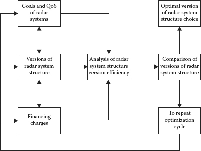
FIGURE 1.1 Block diagram of choice in optimal decision regarding the CRS structure.
Thus, the most characteristic feature of the systems approach to design CRSs is a decision searching by iterative optimization based on computer-aided designing systems. Figure 1.1 represents a block diagram to choose the optimal structure. In accordance with this diagram, the main operations of the system designing are carried out in the following order:
Definition and generation of the end goals, restrictions for number of goals, and problems that must be solved by the system; choice and justification of the system QoS (the efficiency criterion)
Generation of all possible alternative variants to design the system, including impossible versions, at the first sight
Definition of investments to realize each alternative version of the system structure
Designing the models chosen to optimize the alternatives and their software implementation, definition of QoS, and costs of the alternative system structures using the definite model
Comparison of the alternatives and the decision making: either to recommend one or several versions of the radar system structure for further designing or to repeat the whole cycle of optimization process changing a set of initial statements and defining more exactly the QoS (the criterion of effectiveness)
In conclusion, various mathematical methods and procedures are required at the stage of system designing: the theory of probabilities and mathematical statistics; the theory of linear, nonlinear, and dynamic programming; the theory of modeling; etc.
1.2 Main Requirements of Complex Radar Systems
There are various aspects to complex radar system design. Before a new CRS that has not existed previously can be manufactured, a conceptual design has to be performed to guide the actual development. A conceptual design is based on the requirements for the system that will satisfy the customer or user. The result of the conceptual design effort is to provide a list of the radar characteristics as found in the general characteristics of the subsystems that might be employed, namely, transmitter, antenna, receiver, signal processing, and so forth.
Automated CRSs are widely used to solve, for instance, the following problems: air-traffic control, military fighter/attack, ballistic missile defense, battlefield surveillance, navigation, target tracking and control, and so on. In accordance with purposes and the nature of problems that we try to solve, these automated systems can be classified into two groups [1]:
Information radar systems: The main purpose is to collect information about the searched objects (the supervisory radar control systems concerning air, cosmic, and over-water conditions; the meteorological radar systems; the remote sensing radar systems; etc.).
Control radar systems: The main purpose is to solve the problems to control the objects using the data of radar tracking, observation, and measurements (antiaircraft and missile defense systems, air traffic control systems, navigational systems, and so on).
As an example of the CRS of the second group, consider the classical radar antiaircraft and missile defense and control system [2-4]. The block diagram of this control system is shown in Figure 1.2. Elements of the antiaircraft and missile defense system are as follows:
Subsystem of target detection and designation assigned to carry out in a good time the detection and estimation of enemy air target motion parameters
One or several CRSs to fire control assigned to clarification of motion parameters of the annihilation-oriented air targets
Definition of current values of pointing angles and setting time for time fuse with required accuracy
Missile launchers assigned to firing
Facilities to transmit the information-bearing signals between elementary blocks and subsystems of the control system
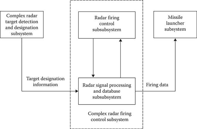
FIGURE 1.2 Radar control system of antiaircraft and missile complex.
The most general QoS (the criterion of effectiveness) of the considered control system, which is generated based on performance purposes, is the so-called averted harm given by [5]
where
is the importance of the defended objective
is the relative damage of the objective caused by the jth armed attack facility under absence of defense
Pij is the probability of the jth armed attack facility damage by the ith defended facility (e.g., missile) N is the number of the armed attack facilities
Lj is the number of missiles assigned to attack the armed attack facility, where
L0 is the missile resource
To ensure the maximal value of damage prevention we must try to increase the probability of target destruction in accordance with Equation 1.2:
where
Ptdj is the probability of success under the target designation with respect to the jth target by the complex radar detection and target designation system
P2j is the probability of success under the parameter clarification of the jth target and definition of firing data by the complex radar control firing system at the condition that the problem of target designation has been solved successfully
P3ij is the probability of destruction of the jth target at the condition that the problems of target designation and control have been solved successfully
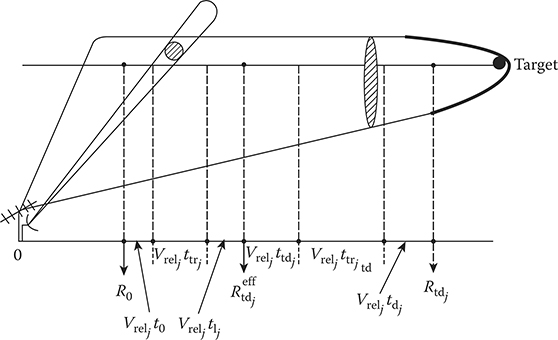
FIGURE 1.3 Emplacement of the complex radar control and target designation systems. (See the notations in text.)
Using Equation 1.3, we can define the QoS of the complex radar control and target designation systems and justify limitations for this quality performance. Consider the case when these systems are placed on the same emplacement (see Figure 1.3). The conditional probability of target destruction by missile can be presented in the following form [6]:
where
is the variance of miss
Reff is the effective radius of target destruction, that is, the radius of sphere, within the limits of which a missile hits and destructs the searched target with the given probability
Based on Equation 1.4, we see that the probability of target destruction is inversely proportional to the variance of miss to deliver a missile to target area, which is characterized by the following constituents:
The error variance to hit the target by missile
The error variance of antitarget guidance by launcher
The error variance of missile fight path
Since these constituents are considered as independent and uncorrelated, the variance of total error with respect to each coordinate from the set
is defined in the following form:
Only the first term in Equation 1.6, the error variance to hit the target by missile , depends on the target designation accuracy given by the control system. Under the fixed values of the second and third terms in Equation 1.6, the error variance of antitarget guidance by launcher and the error variance of missile fight path and given before restrictions to the variance of miss , we are able to define requirements for the control system in accuracy of the observed target coordinates.
The effective radar range of the control system can be determined in the following form (see Figure 1.3):
where
R0 is the far-feld region boundary of destruction area
Vrelj is the relative velocity of the jth target motion with respect to the defended object
t0 is the flight time of missile for the range R0
tlj is the time of lock-in of the jth target to track by the firing control system
ttrj is the tracking time of the jth target to track by the system of firing control, that is, the time from the lock-in instant to the instant of reaching the required accuracy of the target tracking
Thus, to solve the assigned task successfully, the firing control system has to
Possess the radar range ensuring the target destruction on the far-feld region boundary of the destruction area
Ensure the smoothed coordinates of the target with accuracy that is sufficient to reach the searched target
In accordance with a character of assigned tasks, the firing control system must possess the pencil-beam pattern of antenna and restricted zone of searching. For this reason, the main assigned task of the target designation system is to provide the coordinates and motion parameters of targets on the target designation line with accuracy allowing the firing control system to accomplish the target lock-in based on the target designation data without any additional searching or, at least, to limit the additional zone searching to a minimum.
Errors in the target designation are defined by the errors of coordinate measurements carried out by the target designation system, total time of smoothing the target coordinates and parameters, time of transmission, receiving, and processing of target designation commands. Let the target designation area be given by the following coordinates ΔRtd, Δβtd, and Δεtd in the spherical coordinate system. Then the probability to lock-in the target by the control firing system using a single target designation from the CRS of target designation, that is, the probability of success under target designation can be determined in the following form:
where f(ΔR, Δβ, Δε) is the probability density function of target coordinate deviation from the target designation area center.
In the case of systematic bias absence of the target designation and the Gaussian normal distribution of random errors with the variances and the probability of success under the target designation takes the following form:
where
is the integral of probability. From Equation 1.9 it follows that if the required probability of target designation and the coordinates of target designation area are given before, we are able to formulate the requirements to allowable values of the target designation error variances , and .
The aforementioned statements are correct in the case of a single target designation. If there is a possibility to renew and transmit information about the target designation k times (k > 1), then the probability of success under the target designation is given by
The repeated target designation data lead to an increase in time of target designation transmission that requires, finally, increasing the radar range of the system. The required radar range is determined by the following formula (the case of a single target designation):
where
tdj is the time required to detect the jth target
ttrjtd is the time of the jth target tracking by the target designation system to ensure the given accuracy of coordinate and parameter definition and estimation at the extrapolated point for ttdj.
ttdj is the time required to transmit information about the target designation to the firing control system
From Equations 1.9 and 1.12 it follows that the target designation system has to
Possess circular radar scanning
Ensure the radar range required to guarantee the target designation on the reassigned target line
Provide an accuracy of definition and estimation of the searched target coordinates at the predicted point of target designation, which is sufficient to lock-in the target by the control system without additional searching of the target
Thus, reasoning from the considered QoS (the criterion of effectiveness) of the antiaircraft defense system, QoS indices of radar subsystems included in the antiaircraft defense system are
Radar scanning configuration of the CRS: Requirements and configurations of radar scanning of the target designation system and the control system are different. The radar scanning of the control system in angular coordinates is restricted and a way to scan it is specific (spiral, bitmapped, etc.). The radar scanning of the target designation system is circular, as a rule, or sectored and limited on vertical plane by the special cosecant-squared directional diagram shape.
Radar range Rtd (Rtdeff) is the distance, within the limits of which the task performance of each CRS providing information to the missile firing control subsystem is ensured.
Accuracy of information at the given radar range, which is characterized by the covariance matrix of error.
QoS index characterizing influence of the external and internal noise and interferences on the considered CRS and that can be defined by numbers of detected decoy targets, which are tracked by the system over a definite period of time.
QoS indices 2 and 3 are related to each other, since the accuracy of obtaining information about the target depends on the distance between the CRS and the searched target. Moreover, there is a need to take into consideration the statistical nature of the QoS 2, 3, and 4, a relationship between them and the probability of target detection, the probability of false alarm, and the accuracy of coordinate measurements by the radar system. Since the probability of target detection, the probability of false alarm, and the accuracy of coordinate measurements depend on technical parameters of the radar systems also, there is a function between the earlier-mentioned statistical performance and the power, duration, bandwidth of scanning signals, dimensions, and type of transmitting and receiving antenna. These parameters of the radar systems must be defined during system designing.
Consider Equation 1.3 again. Taking into consideration the obtained formulas and relations, we can state that the probability of target destruction can be determined and also used to determine the averted harm given by Equation 1.2 under the known QoS of the target designation system, the control system, and the missile launcher. Consequently, the averted harm criterion (the QoS) can be defined, and it is not changed during the system designing. However, this criterion (the QoS) is related to technical parameters of the designed systems by composite and multiple-valued function and cannot be used in practice to evaluate and compare the solutions of designing. Meanwhile, according to the systems approach under the radar system designing there is a need to take into account the QoS criteria possessing a physical sense, the ability to be determined, and associated with technical parameters of the designed CRS. The criterion, which we have just considered and analyzed, does not satisfy these conditions.
Under designing the CRSs, it is difficult to define a general criterion (QoS) satisfying the afore-mentioned requirements owing to the complicated mathematical model of target searching by the system. For this reason, it is worthwhile to introduce an intermediate QoS instead of the general criterion (QoS) with the purpose to relate the main parameters of the radar systems and signal processing subsystems that are designed.
As a basis for the generalized criterion, we can consider the signal-to-noise ratio (SNR) given by
where
Es is the energy of the received signal
NN+I is the power spectral density of the total noise and interferences
In accordance with the general radar formula for the case of matched signal processing in free space in set noise, we can write [7-11]
where
Ptav is the transmit power
t0 is the observation time
Gt is the transmitting antenna gain
Gr is the receiving antenna gain
λ is the wavelength
Stef is the effective target reflective surface
Rt is the distance to the target
k = 1.38 × 10⁻²³ W/Hz is the Boltzmann constant
T0 is the absolute temperature of signal source
N0 is the power spectral density of set noise
− is the total loss factor
In the case of pulsed radar we can write
where
Pp is the transmit pulse power
τs is the duration of scanning signal
F is the repetition frequency of scanning signals
Under conditions of conflict radar in practice, interferences generated by the enemy are the main noise. The power spectral density of deliberate interference is determined by [12,13]
where
PdI is the power of noise source
α is the coefficient depending on the direction to the noise source and the performance of the noise source directional diagram and CRS directional diagram
RdI is the distance between the CRS and the noise source (the generator of deliberate interference)
ΔfdI is the noise bandwidth
From Equations 1.14 through 1.16 it follows that SNR depends on the main parameters of the CRSs, environment, and target. On the other hand, the main QoS indices of radar signal processing are also expressed by SNR. For instance, the probability of signal detection under the Rayleigh distribution of amplitude and uniform distribution of phase of the signal can be written in the following form:
where γrel is the relative threshold. The root-mean-square value of potential error under delay measurement of the unmodulated in frequency bell-shaped pulse, which can be given by
where τs is the duration of scanning bell-shaped pulse, at the level 0.46 has the following form:
The root-mean-square value of potential error under measurement of the Doppler frequency of the coherent unmodulated in frequency and bell-shaped pulse with duration τs at the level 0.46 takes the following form:
The root-mean-square value of potential error under measurement of the angular coordinates is determined by
where leff is the effective length of antenna aperture normalized with respect to the wavelength and is defined as
where
d is the length of antenna aperture
χ is the constant
Analogous relations take place for more complex models of signal processing techniques.
Thus, the SNR is a generalized parameter that can be used as QoS (the criterion of effectiveness) in the design of the complex radar system and radar signal processing methods.
1.3 Problems of System Design for Automated Complex Radar Systems
The CRS contains a great number of interdependent elements and blocks and belongs to the complex system class. As mentioned earlier, the first step in the design of the system is a definition of functional purposes in the higher order system. In Section 1.2, we have introduced the complex radar target designation and control firing systems. Henceforth, we are limited by consideration of system design problems of the CRS carrying out operations of searching, detection, and tracking a set of targets within the limits of radar coverage and providing information with the required QoS on the reassigned line.
The main task of the system design is the choice and justification of a structural block diagram of the system. For this task, a designing process is based on existing experience of construction of the system with analogous application. In doing so, we should take into consideration the structural stability of the system to changes in functional purposes and initial premises of design, including motivations stimulating a new design process. In this case, we need to design and construct only a small number of elements and blocks in future.

FIGURE 1.4 Structural block diagram of an automated complex radar system.
The structural block diagram of the complex automated radar system is presented in Figure 1.4. This diagram consists of the following blocks [14,15]:
Transmitting and receiving antennae or matched transmitting-receiving antenna
Generator, amplifier, and guidance of scanning signals
Amplifier and transformer of receiving signals
Preprocessing of the target return signals—the receiver processing the target return signals: the filtering, accumulation, detection, and parameter estimation
Reprocessing of the target return signals—a definition of target trajectory parameters
Computer subsystem to control the CRS—the synchronization and adaptation to a changed environment
Data displaying for user
Each listed block is a complex system both by elements and by structure. Each block is an objective of design on the next step of detailed structuring. Figure 1.4 shows us that the optimal design of the CRS, as a whole, is an unsatisfiable problem. In this case, according to the systems approach, the designed system is divided into individual blocks. Under partitioning, we consider a decision rule implicating to establish a single-valued function between a set QoS, as a whole, and individual blocks of the system. We take into consideration dynamical and structural functions. Under such an approach, the design process of the CRS can be divided into the following components satisfying the aforementioned requirements in general:
Definition of energy parameters of the system and designing the generator, amplifier, and guidance of scanning signals
Designing of devices and computer subsystems for signal processing to get information about the target from a set of radar signals in natural and artificial noise, including the target return signals
Designing a subsystem to control the system ensuring a stability of all functions in complex and rapidly changed situations
Energy parameters of the complex radar system are the following:
The power of scanning pulse Pscan
The duration of pulse τs
The transmitting antenna gain Gt
The receiving antenna gain Gr
The effective area of the receiving antenna Seff
Choice of these parameters is accomplished in accordance with the end use of the CRS, the level of development of the corresponding element base, the technology of production, the technology and procedures of adjustment, and taking into account the allowable charges on production manufacturing and operating costs. As a rule, under designing the system, a definition of scanning pulse parameters, ways of scanning pulse generation, and emission is basic, and results of definition are initial data to design the receiving path and target return signal processing algorithms.
In designing the receiving path and the target return signal processing algorithms, the energy parameters of the CRS are considered as the fixed and external parameters. Thus, attention is focused on solution of problems in accordance with which there is a need to define the target return signal processing algorithms ensuring a maximal effect that can be characterized by probability performance and accuracy of definition of the target return signal parameters required by the user. Ultimately, the solution of this problem is reduced to a definition of the target return signal processing algorithms and a choice of computer subsystems for signal processing tasks at all stages, from preamplification and signal conditioning to data preparation and radar information output to the user. To solve these problems, the target return signal processing algorithms well developed in the statistical signal processing area are used, which are invariant to methods of transmission and receiving the signals. Consequently, the receiving path and the target return signal processing algorithms can be developed individually from other blocks and components of the CRSs. Henceforward, a totality of signal processing algorithms and receivers and/or detectors, which are needed to design, is called radar signal processing system.
Considering the radar signal processing system as an autonomous subsystem of the complex radar system, we can define and solve the design problems of the system as applied to its classes and groups, not only the individual CRS, based on functional purposes in high-order systems. The control system of the CRS is, per se, the autonomous system, but by the nature of solving problems, it is the system of higher order in comparison with the considered CRS. Naturally, designing of the control system can be considered as the solo problem within the limits of requirement specification presented for the CRS as a whole.
Thus, the design of the CRS is divided into three individual tasks, which are solved independently of each other but satisfying the conditions of continuous interaction and adjustment of parameters to guarantee a fulfillment and reaching the functional purposes of the systems. Problems of energy parameter definition of the systems are outside the scope of this book.
1.4 Radar Signal Processing System as an Object of Design
The systems approach to design assumes the availability of some basic mathematical models and structures of the radar signal processing systems, which must be put into the basis of new development. Under designing the radar signal processing system, the well-known structure of the receiving path of the CRS is considered as the basic. Optimal signal processing algorithms obtained from the statistical radar theory are used as the basic mathematical models. In accordance with the conclusions of statistical radar theory, the optimal receiver must carry out the following operations (see Figure 1.5) [16-34]:

FIGURE 1.5 Block diagram of operations carried out by the optimal receiver.
Spatial signal processing of the coherent target return signals using the multielement array placed in one or several signal reception points
Time intraperiod signal processing of the coherent target return signals including a nonlinear signal processing, namely, limitation, taking the logarithm, etc., and matched filtering or correlation signal processing
Interperiod compensation of correlated noise and interferences caused by reflection from objects on the Earth’s surface, hydrometeors, and man-made reflectors (artificial passive interferences)
Accumulation of the target return signals and forming some statistics about incoming signals (the decision statistics), based on which we make a decision about the target detection and estimate the target return signal parameters
Comparison of decision statistics with threshold and realization of signal detection algorithms and estimation of signal parameters
Radar imaging of detected targets
Selection and grouping of new radar images by tracking target trajectory tackle and new incoming data for target tracking
Preliminary definition of parameters of new target trajectories
New radar data binding to trajectories of the tracking target
Filtering of the tracking target trajectory parameters during solution of the tracking target trajectory problems
Operations 1 and 2 are the stage of the intraperiod spatial signal processing for coherent single-short pulse. Operations 3-6 are the stage of the interperiod signal processing for a set of target return signals reflected by each target under an antenna beam regular scanning in the radar coverage or at multiple scanning of each direction in the radar coverage. Operations 7-10 are the stage of the surveillance radar signal processing concerning information about trajectories of tracking targets. Thus, there is a consecutive sequence in the radar signal processing by stages. Each stage possesses its own real timescale of signal processing that allows us to carry out an autonomous realization of these stages.
The radar signal processing systems are divided into three classes by the method of implementation: (a) analogous, (b) digital, and (c) analog–digital. Now, the radar signal processing systems of the third class are widely used. However, digital signal processing plays a leading role in exploited and designed CRSs owing to flexibility and universality. We can see a tendency of extension to use the digital signal processing techniques in designing CRSs owing to substitution of analog signal processing by digital one. Successes in digital signal processing, which have been achieved now, allow us to use digital signal processing techniques not only in time signal processing of coherent signals but also in spatial signal processing of coherent signals. Henceforth, we consider digital signal processing techniques starting from the matched filtering of coherent signals.
Solving the tasks of designing radar signal processing subsystems under the fixed energy parameters of the CRS, attention is paid to optimization of receiving path in natural and artificial noise and interferences. All tasks of optimal signal processing are solved by methods and procedures of the theory of statistical decisions. Because of this, the QoS indices of radar signal processing sub-systems are imported from the theory of statistical decisions. For some cases and examples, these QoS indices acquired characteristic features of a radar.
Independent of any application area of CRSs, the main QoS indices of radar signal processing are
Space–time signal processing: the coefficient of energy use given by
where
q2 is the signal-to-interference-plus-noise ratio (SINR)
is the SNR [35]
Radar signal preprocessing:
The probability of signal detection PD
The probability of false alarm PF
The accuracy of definition of the target coordinates and their estimation, which is characterized by the covariance matrix of estimation errors Kmes, in a general case, and by the variance of estimation error
Radar signal reprocessing:
The probability of target trajectory detection
The probability of target trajectory false alarm
The accuracy of definition of the target trajectory parameters, which is characterized by the covariance matrix of estimation errors of the target trajectory parameters
The probability of breaking up in the target tracking Pbr
The earlier-listed QoS indices are associated directly and unambiguously with QoS indices of the CRS, as a whole (see Section 1.3). We can observe a direct relation between them: the higher the QoS indices of radar signal processing subsystems, the higher the QoS indices of the system.
Under implementation of digital signal processing, there is a need to take into consideration some limitations in speed of corresponding devices. For this reason, an important and essential QoS index under digital signal processing is the digital signal processing effort defined by the number of operations at a single realization of the radar signal processing algorithm. Data throughput is an important QoS index under digital signal processing, which can be defined, for example, as the number of target processing by the system simultaneously. Of course, other approaches and methods to estimate the data throughput of radar digital signal processing subsystems are possible [36,37].
In designing CRSs, an initial optimization of signal processing algorithms is carried out by criteria imported from the theory of statistical decisions. For instance, the Neyman-Pearson criterion is the basic criterion in the signal detection theory. The essence of this criterion is the following: we obtain the maximal probability of detection of target return signals (target trajectories) under some limitations in choice of the false alarm probability PF:
where
{v} is the set of possible decision-making rules of detection
vopt from the set {v} corresponds to
is the permissible probability of false alarm
Generally, estimations of signal parameters are optimized by the criterion of minimizing the average risk:
where
ℛav (…) is the average risk
a is the real value of the signal parameter
â is the estimation of real value of the signal parameter
Operations and functions, which are not related to detection of the target return signals and definition and estimation of target return signal parameters, are optimized by criteria corresponding to maximal effect or maximal value of the corresponding QoS in applying restrictions on the energy supply and hardware implementation.
To optimize the system as a whole, the QoS must include all the main indices, that is, it must be a vector in mathematical form. If m subsystems of the CRS are characterized by individual QoS, for example, q1, q2, …, qm, then the system, as a whole, is characterized by the vector Q = (q1, q2, …, qm). The goal of vector optimization is to choose a CRS that possesses the best-case value of the vector Q. At the same time, we assume that the appropriate QoS vector Q is given already. The theory of vector optimization of a CRS is far from completion. Simple methods that are used allow us to reduce the vector analysis directly or marginally to a scalar one. A simple procedure is used in this book. We consider all individual QoS q1, q2, …, qm except the only one, for example, q1, which is the most essential, as there are restrictions with further conditional optimization of the system by this QoS.
The designing of a radar digital signal processing system is divided into two stages: the designing and construction of the digital signal processing algorithms and the designing of the computer subsystems. The designing of the digital signal processing algorithms employed by the CRS is initiated from making clear the main goal of digital signal processing algorithm construction; how the main functions can be generated into the CRS; definition of basic restrictions; QoS; and designing of the objective function. A sequence of the digital signal processing algorithm design is given as follows:
Definition of purpose and main functions of the digital signal processing algorithm.
Designing and construction of logical block diagrams of the digital signal processing algorithms; there is a need to propose several variants.
Off-line testing and processing of the individual digital signal processing algorithms or logical blocks.
Simulation and definition of workability and QoS of the digital signal processing algorithm.
Optimization and construction of the complex digital signal processing algorithm employed by the CRS, which operates in real time. The optimization is carried out by the discrete choice method of trade-off variant from a set of possible ones, which are digital signal processing algorithms corresponding to the given stage of operations. This approach allows us to combine the heuristic procedures and methods based on design-automation systems and optimization of the digital signal processing algorithms.
On the basis of designing and debugging results of a complex digital signal processing algorithm, we are able to define the main parameters of computer subsystems and to state the basic requirements to these parameters with the purpose of realizing all steps of signal processing in the complex radar systems.
Designing of special-purpose computer subsystems (SPCSs) starts from definition of the main parameters and relationships with components of SPCS structure. After definition of functions between parameters of an SPCS as a whole and parameters of structural components of an SPCS, we can formulate the requirements to each elementary structural block of SPCS based on the general requirements to computer subsystems and, by this way, to define the requirements specification to design the CRS as a whole. Relationships between the main parameters and elementary structural blocks of an SPCS are called the parametric balance. The most widely used system balances are the time balance, error balance, memory size balance, reliability balance, balance of costs, and so on [38,39].
Generally, in designing the SPCS structure, the solution can be found using the following variant of the criterion “effectiveness—cost”:
Providing the minimum time to realize the complex digital signal processing algorithm under given restrictions on the equipment investments
Providing the minimal equipment investments under given time of realization of the complex digital signal processing algorithm
In designing CRSs, the second variant is preferable. Ultimately, the designing of an SPCS reduces to definition of the computer subsystems number for different functional purposes and conservation of algorithms to interact between computer subsystems.
In conclusion, we consider an example of systematic sequence under the system design of complex digital signal processing algorithms and computer subsystems for radar signal processing systems (see Figure 1.6). Before designing a CRS, there is a need to define the requirements specification, in which the main purposes and requirements, structural block diagrams of subsystems, and the main restrictions and requirements on the parameters at the system output are described.
Consider the main stages of the CRS design, which are presented in Figure 1.6:
The first stage (block 1) is a formulation of the optimal designing problem, definition of external and internal system parameters and relationships between them, and choice and justification of the objective function of optimal designing. The result is a formalization of the requirements specification.
The second stage is a decomposition of the general problem of system designing (block 2) on a set of simple tasks of subsystem designing and corresponding representation of the general objective function in the form of superposition of objective functions of the optimal subsystem designing. Success in solving the problems of the first and second stages depends on the level of development of the optimal designing methods, in general, and radar signal processing systems, in particular.

FIGURE 1.6 Stages of CRS designing of the digital signal processing algorithms and computer subsystems.
The third stage (block 3) is the designing and investigation of digital signal processing algorithms of subsystems and the generalized algorithm of a CRS. Designing and construction of algorithms is accompanied by comprehensive analysis and testing of digital signal processing algorithms on performance and effectiveness by preliminary established criteria. The main procedure of investigations is a simulation. Success in solution of problems of the third stage depends on the level of development of the theory of signal processing in radar systems.
The fourth and fifth stages (blocks 4 and 5) are the synthesis and selection of equipment and hardware of SPCSs to realize the digital signal processing algorithms in the CRS. Realization of these stages is carried out interacting with previous stages of digital signal processing algorithm design with the purpose to reach the optimal agreement between digital signal processing algorithms and computing facilities by the QoS criterion called “efficiency–cost” Success in problem solving of the fourth and fifth stages depends on the level of development of the theory of computer systems.
The final stage (block 6) of system designing is the evaluation of the effectiveness of the constructed generalized digital signal processing algorithm and the computer system as a whole by the general criterion given in the requirements specification or chosen at the first stage of system designing. Completeness and reliability of this stage depend on the level of development of the theory of operation systems. Results of efficiency evaluation are used to make a decision to finish the system designing stage and complementation to technical designing stage if the requirements specification and required QoS by efficiency criterion are satisfied. In the opposite case, there is a need to change the requirements specification and to repeat all stages of system design again.
Henceforward, in this book, we follow the considered sequence of system designing stages with attention to construction of the digital signal processing algorithms and choice of computer systems for their realization in CRSs.
1.5 Summary and Discussion
The basic aspects of systems approach to design CRSs discussed in this chapter are the following.
The systems approach is considered to design CRSs. The designing process is divided into two sufficiently pronounced stages—system designing and engineering designing. A conception of complex information and control system integrity, including a CRS, makes specific owing to the idea of backbone communications, for example, structural and control communications. At the stage of system designing, the main factor to consider is the structure or architecture of the future complex information and control system, including a CRS. At the stage of engineering designing, the important issue is the choice and development of a fixed totality of CRS elements and communications between them.
Any CRS cannot be imagined without the environment. The main problem is to define an optimal boundary between the system and the environment. The environment, facilities of counteracting forces, level of development of the element base and technologies, economic factors, and human element are the factors affecting the operation of a system. Based on the methodology viewpoint, the definite aspects of the systems approach were defined to design any complex information and control system, including a CRS.
In the design of such systems, we widely use mathematical models, simulation models, and modeling as a process of representation of the CRS by an adequate model with subsequent test operation to obtain information about its functioning. The most characteristic feature of the systems approach is to search for a decision by iterative optimization based on computer-aided designing systems. The main operations of the system design are the definition and generation of the end goals; generation of all possible alternative variants; definition of investments to realize each alternative version of the system structure; designing the models chosen to optimize alternatives and their software implementation; and comparison of alternatives and the decision making.
Automated CRSs are widely used to solve different problems, namely, air-traffic control, military fighter/attack, ballistic missile defense, battlefield surveillance, navigation, target tracking and control, and so on. Based on the purposes and nature of problems, automated CRSs can be classified into two groups: information radar systems and control radar systems.
As an example, the main requirements and QoS (the criterion of effectiveness) of classical radar antiaircraft and missile defense and control systems are discussed. Reasoning from the considered QoS (the criterion of effectiveness) of the antiaircraft defense system, QoS indices of radar subsystems included in the antiaircraft defense system are defined. According to the systems approach in CRS designing, there is a need to take into account the QoS criteria possessing a physical sense, the ability to be determined, and associated with technical parameters of the designed system. In designing CRSs, it is difficult to define a general criterion (QoS) satisfying the requirements mentioned earlier owing to a complicated mathematical model to search for a target. For this reason, it is worth introducing an intermediate QoS instead of the general criterion (QoS) with the purpose of relating the main parameters of the systems and signal processing subsystems that are designed. It has been defined that the SNR is a generalized parameter that can be used as QoS (the criterion of effectiveness) in the design of the CRS and radar signal processing methods.
The main task of the system design is the choice and justification of a structural block diagram of the CRS. In this task, the designing process is based on the existing experience of construction of the system with analogous application. In doing so, we should take into consideration the structural stability of the system to changes in functional purposes and initial premises of design, including motivations stimulating a new design process. In this case, we need to design and construct only a small number of elements and blocks in the future.
The designing problem of the CRS is divided into three individual tasks, which are solved independently of each other but satisfy the conditions of continuous interaction and adjustment of parameters to guarantee fulfillment and enable achieving the functional goals of the systems. They are as follows:
Definition of the target return signal processing algorithms to define the parameters of the target return signal required by the user
Choice of computer subsystems for signal processing tasks at all stages, from preamplification and signal conditioning to data preparation and radar information output to the user
Definition of energy parameters of the CRSs, which is outside the scope of this book
Optimal signal processing algorithms obtained from the statistical radar theory are used as the basic mathematical models. There is a consecutive sequence in radar signal processing by stages. Each stage possesses its own real time scale of signal processing that allows us to carry out an autonomous realization of these stages. Solving the tasks of radar signal processing sub-system designing under the fixed energy parameters of the system, the main focus is on optimization of the receiving path in natural and artificial noise and interferences. All tasks of optimal signal processing are solved by methods and procedures of the theory of statistical decisions.
Independent of the application area of CRSs, the main QoS indices of radar signal processing are (a) space–time signal processing: the coefficient of energy use; (b) radar signal preprocessing: the probability of signal detection; the probability of false alarm; and the accuracy of definition of the target coordinates and their estimation, which is characterized by the covariance matrix of estimation errors, in a general case, and by the variance of estimation error; (c) radar signal reprocessing: the probability of target trajectory detection; the probability of target trajectory false alarm; the accuracy of definition of the target trajectory parameters, which is characterized by the covariance matrix of estimation errors of the target trajectory parameters; and the probability of breaking up in the target tracking. These QoS indices are associated directly and unambiguously with the QoS indices of the complex radar system, as a whole. We can observe a direct relation between them: the higher the QoS indices of radar signal processing subsystems, the higher the QoS indices of the complex radar system, as a whole.
The designing of a radar digital signal processing subsystem is divided into two stages: designing and construction of the digital signal processing algorithms and designing of the computer subsystems. The designing of the digital signal processing algorithms employed by the complex radar system is initiated from making clear the main goal of digital signal processing algorithm construction; how the main functions can be generated into the complex radar system; definition of basic restrictions; QoS; and designing of the objective function. Designing of computer subsystems with special purpose, which are called SPCS, starts from definition of the main parameters and relationships with components of SPCS structure. After definition of functions between parameters of SPCS as a whole and parameters of structural components of SPCS, we can formulate the requirements of each elementary structural block of SPCS based on the general requirements to computer subsystems and, in this way, define the requirements specification in designing the complex radar system as a whole. Generally, under designing the SPCS structure the solution can be found using the following variant of the criterion “effectiveness–cost.”
References
1. Skolnik, M.I. 2008. Radar Handbook. 3rd edn. New York: McGraw-Hill, Inc.
2. Tzvetkov, A. 1971. Principles of Quantitative Ratings of Complex Radar System Efficiency. Moscow, Russia: Soviet Radio.
3. Hovanessian, S. 1984. Radar System Design and Analysis. Norwood, MA: Artech House, Inc.
4. Meyer, D. and H. Mayer. 1973. Radar Target Detection: Handbook of Theory and Practice. New York: Academic Press.
5. Drujinin, B. and D. Kontorov. 1976. Problems of Military Systems Engineering. Moscow, Russia: Military Press.
6. Gutkin, L.S., Pestryakov, V.V., and V.H. Tipugin. 1970. Radio Control. Moscow, Russia: Soviet Radio.
7. Skolnik, M.I. 2001. Introduction to Radar Systems. New York: McGraw-Hill, Inc.
8. Lacomme, P., Hardange, J.P., Marchais, J.C., and E. Normant. 2001. Air and Spaceborne Radar Systems: An Introduction. New York: William Andrew Publishing.
9. Tait, P. 2005. Introduction to Radar Target Recognition. Cornwall, U.K.: IEE Press.
10. Levanon, N. and E. Mozeson. 2004. Radar Signals. New York: IEEE Press, John Wiley & Sons, Inc.
11. Barton, D.K. 2005. Modern Radar System Analysis and Modeling. Canton, MA: Artech House, Inc.
12. Stimson, G.W. 1998. Introduction to Airborne Radar. 2nd edn. Raleigh, NC: SciTech Publishing, Inc.
13. Nitzberg, R. 1999. Radar Signal Processing and Adaptive Systems. Norwood, MA: Artech House, Inc.
14. Streetly, M. 2000. Radar and Electronic Warfare Systems. 11th edn. Surrey, U.K.: James Information Group.
15. Guerci, J.R. 2003. Space-Time Adaptive Processing for Radar. Norwood, MA: Artech House, Inc.
16. Barkat, M. 2005. Signal Detection and Estimation. 2nd Edn., Norwood, MA: Artech House, Inc.
17. DiFranco, J.V. and W.L. Rubin. 1980. Radar Detection. Norwood, MA: Artech House, Inc.
18. Edde, B. 1993. Radar Principles, Technology, Application. Englewood Cliffs, NJ: Prentice Hall, Inc.
19. Kay, S.M. 1993. Fundamentals of Statistical Signal Processing—Estimation Theory. Vol. I. Englewood Cliffs, NJ: Prentice Hall, Inc.
20. Kay, S.M. 1998. Fundamentals of Statistical Signal Processing—Detection Theory. Vol. II. Englewood Cliffs, NJ: Prentice Hall, Inc.
21. Knott, E.F., Shaeffer, J.F., and M.T. Tuley. 1993. Radar Cross Section. 2nd edn. Norwood, MA: Artech House, Inc.
22. Mahafza, B.R. 1998. Introduction to Radar Analysis. Boca Raton, FL: CRC Press, Taylor & Francis Group.
23. Mahafza, B.R. 2000. Radar System Analysis and Design Using MATLAB. Boca Raton, FL: CRC Press.
24. Nathanson, F.E. 1991. Radar Design Principles. 3rd edn. New York: McGraw Hill, Inc.
25. Peebles, Jr., P.Z. 1998. Radar Principles. New York: John Wiley & Sons, Inc.
26. Richards, M.A. 2005. Fundamentals of Radar Signal Processing. Englewood Cliffs, NJ: Prentice Hall, Inc.
27. Brookner, E. 1988. Aspects of Modern Radar. Boston, MA: Artech House, Inc.
28. Franceschetti, G. and. R. Lanari. 1999. Synthetic Aperture Radar Processing. Boca Raton, FL: CRC Press.
29. Johnson, D.H. and D.E. Dudgeon. 1993. Array Signal Processing: Concepts and Techniques. Englewood Cliffs, NJ: Prentice Hall, Inc.
30. Klemm, R. 1998. Space-Time Adaptive Signal Processing: Principles and Applications. London, U.K.: INSPEC/IEEE.
31. Sullivan, R.J. 2000. Microwave Radar: Imaging and Advanced Concepts. Boston, MA: Artech House, Inc.
32. Tuzlukov, V.P. 2001. Signal Detection Theory. New York: Springer-Verlag.
33. Tuzlukov, V.P. 2002. Signal Processing Noise. Boca Raton, FL: CRC Press.
34. Tuzlukov, V.P. 2004. Signal and Image Processing in Navigational Systems. Boca Raton, FL: CRC Press.
35. Van Trees, H.L. 2002. Optimum Array Processing: Part IV of Detection, Estimation, and Modulation Theory. New York: John Wiley & Sons, Inc.
36. Tsui, J.B. 2004. Digital Techniques for Wideband Receivers. 2nd edn. Raleigh, NC: SciTech Publishing, Inc.
37. Bogler, P.L. 1990. Radar Principles with Applications to Tracking Systems. New York: John Wiley & Sons, Inc.
38. Cumming, I.G. and. F.N. Wong. 2005. Digital Signal Processing of Synthetic Aperture Radar Data. Norwood, MA: Artech House, Inc.
39. Long, M.W. 2001. Radar Reflectivity of Land and Sea. 3rd edn. Boston, MA: Artech House, Inc.