
Chapter 2
Software Development Life Cycle Models Life Cycle Models
In this chapter—
2.1 PHASES OF SOFTWARE PROJECT
A software project is made up of a series of phases. Broadly, most software projects comprise the following phases.
- Requirements gathering and analysis
- Planning
- Design
- Development or coding
- Testing
- Deployment and maintenance
2.1.1 Requirements Gathering and Analysis
During requirements gathering, the specific requirements of the software to be built are gathered and documented. If the software is bespoke software, then there is a single customer who can give these requirements. If the product is a general-purpose software, then a product marketing team within the software product organization specifies the requirements by aggregating the requirements of multiple potential customers. In either case, it is important to ensure that the right requirements are captured at every stage. The requirements get documented in the form of a System Requirements Specification (SRS) document. This document acts as a bridge between the customer and the designers chartered to build the product.
2.1.2 Planning
The purpose of the planning phase is to come up with a schedule, the scope, and resource requirements for a release. A plan explains how the requirements will be met and by which time. It needs to take into account the requirements—what will be met and what will not be met—for the current release to decide on the scope for the project, look at resource availability, and to come out with set of milestones and release date for the project. The planning phase is applicable for both development and testing activities. At the end of this phase, both project plan and test plan documents are delivered.
2.1.3 Design
The purpose of the design phase is to figure out how to satisfy the requirements enumerated in the System Requirements Specification document. The design phase produces a representation that will be used by the following phase, the development phase. This representation should serve two purposes. First, from this representation, it should be possible to verify that all the requirements are satisfied. Second, this representation should give sufficient information for the development phase to proceed with the coding and implementation of the system. Design is usually split into two levels—high-level design and low-level or a detailed design. The design step produces the system design description (SDD) document that will be used by development teams to produce the programs that realize the design.
2.1.4 Development or Coding
Design acts as a blueprint for the actual coding to proceed. This development or coding phase comprises coding the programs in the chosen programming language. It produces the software that meets the requirements the design was meant to satisfy. In addition to programming, this phase also involves the creation of product documentation.
2.1.5 Testing
As the programs are coded (in the chosen programming language), they are also tested. In addition, after the coding is (deemed) complete, the product is subjected to testing. Testing is the process of exercising the software product in pre-defined ways to check if the behavior is the same as expected behavior. By testing the product, an organization identifies and removes as many defects as possible before shipping it out.
2.1.6 Deployment and Maintenance
Once a product is tested, it is given to the customers who deploy it in their environments. As the users start using the product in their environments, they may observe discrepancies between the actual behavior of the product and what they were given to expect (either by the marketing people or through the product documentation). Such discrepancies could end up as product defects, which need to be corrected. The product now enters the maintenance phase, wherein the product is maintained or changed to satisfy the changes that arise from customer expectations, environmental changes, etc. Maintenance is made up of corrective maintenance (for example, fixing customer-reported problems), adaptive maintenance (for example, making the software run on a new version of an operating system or database), and preventive maintenance (for example, changing the application program code to avoid a potential security hole in an operating system code).
2.2 QUALITY, QUALITY ASSURANCE, AND QUALITY CONTROL
A software product is designed to satisfy certain requirements of a given customer (or set of customers). How can we characterize this phrase—“satisfying requirements”? Requirements get translated into software features, each feature being designed to meet one or more of the requirements. For each such feature, the expected behavior is characterized by a set of test cases. Each test case is further characterized by
Quality is meeting the requirements expected of the software, consistently and predictably.
- The environment under which the test case is to be executed;
- Inputs that should be provided for that test case;
- How these inputs should get processed;
- What changes should be produced in the internal state or environment; and
- What outputs should be produced.
The actual behavior of a given software for a given test case, under a given set of inputs, in a given environment, and in a given internal state is characterized by
- How these inputs actually get processed;
- What changes are actually produced in the internal state or environment; and
- What outputs are actually produced.
If the actual behavior and the expected behavior are identical in all their characteristics, then that test case is said to be passed. If not, the given software is said to have a defect on that test case.
How do we increase the chances of a product meeting the requirements expected of it, consistently and predictably? There are two types of methods—quality control and quality assurance.
Quality control attempts to build a product, test it for expected behavior after it is built, and if the expected behavior is not the same as the actual behavior of the product, fixes the product as is necessary and rebuilds the product. This iteration is repeated till the expected behavior of the product matches the actual behavior for the scenarios tested. Thus quality control is defect-detection and defect-correction oriented, and works on the product rather than on the process.
Quality assurance, on the other hand, attempts defect prevention by concentrating on the process of producing the product rather than working on defect detection/correction after the product is built. For example, instead of producing and then testing a program code for proper behavior by exercising the built product, a quality assurance approach would be to first review the design before the product is built and correct the design errors in the first place. Similarly, to ensure the production of a better code, a quality assurance process may mandate coding standards to be followed by all programmers. As can be seen from the above examples, quality assurance normally tends to apply to all the products that use a process. Also, since quality assurance continues throughout the life of the product it is everybody's responsibility; hence it is a staff function. In contrast, the responsibility for quality control is usually localized to a quality control team. Table 2.1 summarizes the key distinctions between quality control and quality assurance.
Table 2.1 Difference between quality assurance and quality control.
| Quality Assurance | Quality Control |
|---|---|
| Concentrates on the process of producing the products | Concentrates on specific products |
| Defect-prevention oriented | Defect-detection and correction oriented |
| Usually done throughout the life cycle | Usually done after the product is built |
| This is usually a staff function | This is usually a line function |
| Examples: reviews and audits | Examples: software testing at various levels |
We will see more details of quality assurance methods such as reviews and audits in Chapter 3. But the focus of the rest of this book is on software testing, which is essentially a quality control activity. Let us discuss more about testing in the next section.
2.3 TESTING, VERIFICATION, AND VALIDATION
The narrow definition of the term “testing” is the phase that follows coding and precedes deployment. Testing is traditionally used to mean testing of the program code. However, coding is a downstream activity, as against requirements and design that occur much earlier in a project life cycle. Given that the objective of a software project is to minimize and prevent defects, testing of program code alone is not sufficient. As we saw in the last chapter, defects can creep in during any phase and these defects should be detected as close to the point of injection as possible and not wait till the testing of programs. Hence against this, if each phase is “tested” separately as and when the phase is completed (or, better still, as the phase is being executed), then defects can be detected early, thereby reducing the overall costs.
Verification is the process of evaluating a system or component to determine whether the products of a given phase satisfy the conditions imposed at the start of that phase.
Timely testing increases the chances of a product or service meeting the customer's requirements. When a product is tested with appropriate and realistic tests that reflect typical usage patterns by the intended users, the chances of the product satisfying the customer's requirement is much higher. While testing does not guarantee zero defects, effective testing certainly increases the chances of customer acceptance of the software.
The purpose of testing is to uncover defects in the system (and to have someone fix the defects). Testing is done by a set of people within a software product (or service) organization whose goal and charter is to uncover the defects in the product before it reaches the customer (see Section 1.3). As we saw in the previous chapter, the purpose of testing is NOT to prove that the product has no defects. The purpose of software testing is to find defects in a software product. As we will see in the chapters on people and organizational issues (Chapters 13, 14), the reward systems and the organization structures should create and foster an environment that encourages this purpose of testing.
Validation is the process of evaluating a system or component during or at the end of the development process to determine whether it satisfies specified requirements.
Testing is NOT meant to replace other ways of ensuring quality (like reviews). It is one of the methods to detect defects in a software product. There are other methods that achieve the same function. For example, we will see later that following well-defined processes and standards reduces the chances of defects creeping into a software. We will also discuss other methods like reviews and inspections, which actually attempt to prevent defects coming into the product. To be effective, testing should complement, supplement, and augment such quality assurance methods discussed in the previous section.
The idea of catching defects within each phase, without letting them reach the testing phase, leads us to define two more terms—verification and validation.
During the requirements gathering phase, the requirements are faithfully captured. The SRS document is the product of the requirements phase. To ensure that requirements are faithfully captured, the customer verifies this document. The design phase takes the SRS document as input and maps the requirements to a design that can drive the coding. The SDD document is the product of the design phase. The SDD is verified by the requirements team to ensure that the design faithfully reflects the SRS, which imposed the conditions at the beginning of the design phase.
Verification takes care of activities to focus on the question “Are we building the product right?” and validation takes care of a set of activities to address the question “Are we building the right product?”
To build the product right, certain activities/conditions/procedures are imposed at the beginning of the life cycle. These activities are considered “proactive” as their purpose is to prevent the defects before they take shape. The process activities carried out during various phases for each of the product releases can be termed as verification. Requirements review, design review, and code review are some examples of verification activities.
To build the right product, certain activities are carried out during various phases to validate whether the product is built as per specifications. These activities are considered “reactive” as their purpose is to find defects that affect the product and fix them as soon as they are introduced. Some examples of validation include unit testing performed to verify if the code logic works, integration testing performed to verify the design, and system testing performed to verify that the requirements are met.
Quality Assurance = Verification
Quality Control = Validation = Testing
To summarize, there are different terminologies that may stand for the same or similar concepts. For all practical purposes in this book, we can assume verification and quality assurance to be one and the same. Similarly quality control, validation, and testing mean the same.
2.4 PROCESS MODEL TO REPRESENT DIFFERENT PHASES
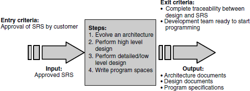
A process model is a way to represent any given phase of software development that effectively builds in the concepts of validation and verification to prevent and minimize the delay between defect injection and defect detection (and eventual correction). In this model, each phase of a software project is characterized by the following.
- Entry criteria, which specify when that phase can be started. Also included are the inputs for the phase.
- Tasks, or steps that need to be carried out in that phase, along with measurements that characterize the tasks.
- Verification, which specifies methods of checking that the tasks have been carried out correctly.
- Exit criteria, which stipulate the conditions under which one can consider the phase as done. Also included are the outputs for only the phase.
This model, known as the Entry Task Verification eXit or ETVX model, offers several advantages for effective verification and validation.
- Clear entry criteria make sure that a given phase does not start prematurely.
- The verification for each phase (or each activity in each phase) helps prevent defects, or at least, minimizes the time delay between defect injection and defect detection.
- Documentation of the detailed tasks that comprise each phase reduces the ambiguity in interpretation of the instructions and thus minimizes the variations that can come from repeated executions of these tasks by different individuals.
- Clear exit criteria provide a means of validation of the phase, after the phase is done but before handing over to the next phase.
An example of applying the ETVX model to the design phase is presented in Figure 2.1.
2.5 LIFE CYCLE MODELS
The ETVX model characterizes a phase of a project. A Life Cycle model describes how the phases combine together to form a complete project or life cycle. Such a model is characterized by the following attributes.
The activities performed In any given software project, apart from the most common activities or phases—requirements gathering, design, development, testing, and maintenance—there could be other activities as well. Some of these activities could be technical activities (for example, porting) and some could be non-technical (for example, hiring).
The deliverables from each activity Each activity produces a set of deliverables, which are the end products of that activity. For example, the requirements gathering phase produces the SRS document, the design phase produces the SDD document, and so on.
Methods of validation of the deliverables The outputs produced by a given activity represent the goal to be satisfied by that activity. Hence it is necessary to have proper validation criteria for each output.
The sequence of activities The different activities work together in unison in a certain sequence of steps to achieve overall project goals. For example, the process of requirements gathering may involve steps such as interviews with customers, documentation of requirements, validation of documented requirements with customers, and freezing of requirements. These steps may be repeated as many times as needed to get the final frozen requirements.
Methods of verification of each activity, including the mechanism of communication amongst the activities The different activities interact with one another by means of communication methods. For example, when a defect is found in one activity and is traced back to the causes in an earlier activity, proper verification methods are needed to retrace steps from the point of defect to the cause of the defect.
We will now look at some of the common life cycle models that are used in software projects. For each model, we will look at:
- a brief description of the model;
- the relationship of the model to verification and validation activities; and
- typical scenarios where that life cycle model is useful.
2.5.1 Waterfall Model
In the Waterfall model, a project is divided into a set of phases (or activities). Each phase is distinct, that is, there are clear lines of separation between the phases, with very clear demarcation of the functions of each of the phases. A project starts with an initial phase, and upon completion of the phase, moves on to the next phase. On the completion of this phase, the project moves to the subsequent phase and so on. Thus the phases are strictly time sequenced.
We depict one example of a project in the Waterfall model in Figure 2.2. The project goes through a phase of requirements gathering. At the end of requirements gathering, a System Requirements Specification document is produced. This becomes the input to the design phase. During the design phase, a detailed design is produced in the form of a System Design Description. With the SDD as input, the project proceeds to the development or coding phase, wherein programmers develop the programs required to satisfy the design. Once the programmers complete their coding tasks, they hand the product to the testing team, who test the product before it is released.

If there is no problem in a given phase, then this method can work, going in one direction (like a waterfall). But what would happen if there are problems after going to a particular phase? For example, you go into the design phase and find that it is not possible to satisfy the requirements, going by the current design approach being used. What could be the possible causes and remedies? You may try an alternative design if possible and see if that can satisfy the requirements. If there are no alternative design approaches possible, then there must be feedback to the requirements phase to correct the requirements.
A Waterfall model is characterized by three attributes.
The project is divided into separate, distinct phases.
Each phase communicates to the next through pre-specified outputs.
When an error is detected, it is traced back to one previous phase at a time, until it gets resolved at some earlier phase.
Let us take the example one step further. Suppose a design was created for a given set of requirements and the project passed on to the programming/development phase. At this point of time, it was found that it was not possible to develop the programs because of some limitations. What would you do? One approach would be to try out alternative strategies in the development phase so that the design could still be satisfied. Another possibility could be that there are flaws in design that cause conflicts during development and hence the design has to be revisited. When the design phase is revisited—like in the previous case—it may happen that the problem may have to be addressed in the requirements phase itself. So, a problem in one phase could potentially be traced back to any of the previous phases.
Since each phase has an output, the latter can be validated against a set of criteria. To increase the effectiveness, the completion criteria for each output can be published a priori. Before a phase starts, the completion criteria for the previous phase can be checked and this can act as a verification mechanism for the phase. This can minimize the kind of delays we discussed in the example above.
The main strength of the Waterfall Model is its simplicity. The model is very useful when a project can actually be divided into watertight compartments. But very few software projects can be divided thus. The major drawback in the Waterfall model arises from the delay in feedback among the phases, and thus the ineffectiveness of verification and validation activities. An error in one phase is not detected till at least the next phase. When a given phase detects an error, the communication is only to the immediately preceding phase. This sequential nature of communication among the phases can introduce inordinate delays in resolving the problem. The reduced responsiveness that is inherent in the model and the fact that the segregation of phases is unrealistic severely restricts the applicability of this model.
2.5.2 Prototyping and Rapid Application Development Models
Prototyping and Rapid Application Development (RAD) models recognize and address the following issues.
- Early and frequent user feedback will increase the chances of a software project meeting the customers’ requirements.
- Changes are unavoidable and the software development process must be able to adapt itself to rapid changes.
A Prototyping model uses constant user interaction, early in the requirements gathering stage, to produce a prototype.
The proto-type is used to derive the system requirements specification and can be discarded after the SRS is built.
An appropriate life cycle model is chosen for building the actual product after the user accepts the SRS.
The Prototyping model comprises the following activities.
- The software development organization interacts with customers to understand their requirements.
- The software development organization produces a prototype to show how the eventual software system would look like. This prototype would have the models of how the input screens and output reports would look like, in addition to having some “empty can functionality” to demonstrate the workflow and processing logic.
- The customer and the development organization review the prototype frequently so that the customer's feedback is taken very early in the cycle (that is, during the requirements gathering phase).
- Based on the feedback and the prototype that is produced, the software development organization produces the System Requirements Specification document.
- Once the SRS document is produced, the prototype can be discarded.
- The SRS document is used as the basis for further design and development.
Thus, the prototype is simply used as a means of quickly gathering (the right) requirements. This model has built-in mechanisms for verification and validation of the requirements. As the prototype is being developed, the customer's frequent feedback acts as a validation mechanism. Once the SRS is produced, it acts as the verification mechanism for the design and subsequent steps. But the verification and validation activities of the subsequent phases are actually dictated by the life cycle model that is followed after the SRS is obtained.
This model is obviously advantageous when a customer can participate by giving feedback. This model is also useful in cases where the feedback can be easily quantified and incorporated, for example, determining user interface, predicting performance, and so on.
For a general-purpose product, which is meant for many customers, there is no single customer whose feedback can be taken as final. In these cases, a product manager in the marketing group of the product vendor usually plays the role of the eventual customer. Hence the applicability of this model is somewhat limited to general-purpose products. Furthermore, the prototype is used as a means of capturing requirements and is not necessarily meant to be used afterwards. Oftentimes, the prototype (or parts of the prototype) makes its way to becoming the product itself. This can have undesirable effects as the prototype usually employs several short cuts, unstructured methods, and tools to achieve a quick turnaround. Such short cuts are potential sources of defects in live environments and thus can place a heavy burden on maintenance and testing.
The Rapid Application Development model is a variation of the Prototyping Model. Like the Prototyping Model, the RAD Model relies on feedback and interaction by the customers to gather the initial requirements. However, the Prototyping model differs from the RAD Model on two counts.
First, in the RAD Model, it is not a prototype that is built but the actual product itself. That is, the built application (prototype, in the previous model) is not discarded. Hence, it is named Rapid Application Development model.
Second, in order to ensure formalism in capturing the requirements and proper reflection of the requirements in the design and subsequent phases, a Computer Aided Software Engineering (CASE) tool is used throughout the life cycle, right from requirements gathering. Such CASE tools have
- methodologies to elicit requirements;
- repositories to store the gathered requirements and all downstream entities such as design objects; and
- mechanisms to automatically translate the requirements stored in the repositories to design and generate the code in the chosen programming environment.
The methodologies provided by a CASE tool can provide inbuilt means of verification and validation. For example, the tool may be able to automatically detect and resolve inconsistencies in data types or dependencies. Since the design (and, perhaps, even the program code) can be automatically generated from the requirements, the validation can be very complete, extending to all the downstream phases, unlike the Prototyping model.
This method can have wider applicability for even general-purpose products. The automatic generation of the design and programs produced by a CASE tool makes this model more attractive. The cost of such CASE tools is a factor that an organization would have to consider before deciding on the use of this model for a given project. In addition, CASE tools and this model is generally more suited for applications projects rather than systems type projects.
2.5.3 Spiral or Iterative Model
The Spiral or Iterative model follows a process in which the requirements gathering, design, coding, and testing are performed iteratively till all requirements are met. There is also a good amount of overlap among the activities of requirements gathering, design, coding, and testing following this model. What phase the product is in is difficult to conclude as each requirement can be at a different phase. The only conclusion that can be made is at what phase each of the requirements is in. If a defect is produced in any phase of a given requirement, it may cause that requirement to revisit an earlier phase. This model enables incremental development whereby the product evolves, with requirements getting added to it dynamically. This enables the product to be demonstrated, at any point of time, with the functionality available at that point of time. It also enables the “increments” to be sent to the customer for approval. The progress of the product can be seen from the beginning of the project as the model delivers “increments” at regular intervals. Even though it will be very difficult to plan a release date following this model, it allows the progress to be tracked and the customer approvals to be obtained at regular intervals, thereby reducing the risk of finding major defects at a later point of time. Table 2.2 gives an example of phases for some of the requirements in the product.
Table 2.2 Some product requirements and phases.
| Requirements | Status/Phase currently in |
|---|---|
| Requirement-1 | Coding |
| Requirement-2 | Design |
| Requirement-3 | Requirement |
| Requirement-4 | Testing |
| Requirement-5 | Released |
Figure 2.3 (the coloured figure is available on Illustrations) depicts the Spiral model and the phases involved in the model, for the example on Table 2.2. As can be seen, each requirement is “spiraling outwards” through the different phases as the entire project evolves.

2.5.4 The V Model
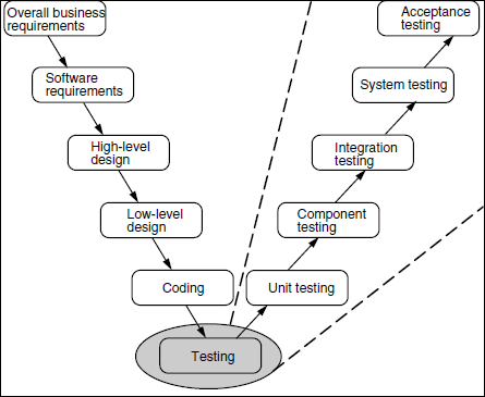
The Waterfall Model viewed testing as a post-development (that is, post-coding) activity. The Spiral Model took this one step further and tried to break up the product into increments each of which can be tested separately. The V Model starts off being similar to the Waterfall Model in that it envisages product development to be made up of a number of phases or levels. However, the new perspective that the V Model brings in is that different types of testing apply at different levels. Thus, from a testing perspective, the type of tests that need to be done at each level vary significantly.
For instance, consider a typical product development activity represented as a Waterfall Model earlier in Figure 2.2. The system starts with the overall business requirements from the point of view of customers. These requirements cover hardware, software, and operational requirements. Since our focus is on the software, moving from overall requirements to software requirements becomes the next step. In order to realize the software requirements, the proposed software system is envisaged as a set of subsystems that work together. This high-level design (of breaking the system into subsystems with identified interfaces) then gets translated to a more detailed or low-level design. This detailed design goes into issues like data structures, algorithm choices, table layouts, processing logic, exception conditions, and so on. It results in the identification of a number of components, each component realized by program code written in appropriate programming languages.
Given these levels, what kind of tests apply in each of these levels? To begin with, for overall business requirements, eventually whatever software is developed should fit into and work in this overall context and should be accepted by the end users, in their environment. This testing, the final proof of the pudding, is acceptance testing. But, before the product is deployed in the customer's environment, the product vendor should test it as an entire unit to make sure that all the software requirements are satisfied by the product that is developed. This testing of the entire software system can be called system testing. Since high-level design views the system as being made up of interoperating and integrated (software) subsystems, the individual subsystems should be integrated and tested together before a full blown system test can be done. This testing of high-level design corresponds to integration testing. The components that are the outputs of the low-level design have to be tested independently before being integrated. Thus, the testing corresponding to the low-level design phase is component testing. Finally, since coding produces several program units, each of these smaller program units have to be tested independently before trying to combine them together to form components. This testing of the program units forms unit testing.
Figure 2.4 depicts the different types of testing that apply to each of the steps. For simplicity, we have not shown the planning phase as a separate entity since it is common for all testing phases. But, it is not possible to execute any of these tests until the product is actually built. In other words, the step called “testing” is now broken down into different sub-steps called acceptance testing, system testing, and so on as shown in Figure 2.4. So, it is still the case that all the testing execution related activities are done only at the end of the life cycle.
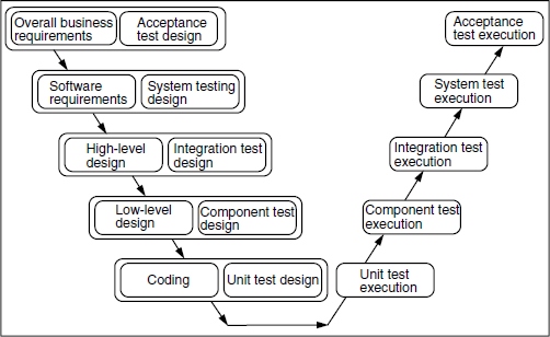
Even though the execution of the tests cannot be done till the product is built, the design of tests can be carried out much earlier. In fact, if we look at the aspect of skill sets required for designing each type of tests, the people best suited to design each of these tests are those who are actually performing the function of creating the corresponding artifact. For example, the best people to articulate what the acceptance tests should be are the ones who formulate the overall business requirements (and, of course, the customers, where possible). Similarly, the people best equipped to design the integration tests are those who know how the system is broken into subsystems and what the interfaces between the subsystems are—that is, those who perform the high-level design. Again, the people doing development know the innards of the program code and thus are best equipped to design the unit tests.
The V-model splits testing into two parts—design and execution.
Test design is done early, while test execution is done in the end.
There are different types of tests for each phase of life cycle.
Not only are the skill sets required for designing these different types of tests different, but also, there is no reason to defer the designing of the tests till the very end. As and when each activity on the left-hand side of the “V” is being carried out, the design of the corresponding type of tests can be carried out. By performing an early design of the tests and deferring only the test execution till the end, we achieve three important gains.
- First, we achieve more parallelism and reduce the end-of-cycle time taken for testing.
- Second, by designing tests for each activity upfront, we are building in better upfront validation, thus again reducing last-minute surprises.
- Third, tests are designed by people with appropriate skill sets.
This is the basis for the V Model, which presents excellent advantages for verification and validation. As shown in Figure 2.5, for each type of test, we move the design of tests upstream, along with the actual activities and retain the test execution downstream, after the product is built.
2.5.5 Modified V Model
The V Model split the design and execution portion of the various types of tests and attached the test design portion to the corresponding earlier phases of the software life cycle.
An assumption made there was that even though the activity of test execution was split into execution of tests of different types, the execution cannot happen until the entire product is built. For a given product, the different units and components can be in different stages of evolution. For example, one unit could be still under development and thus be in the unit-testing phase whereas another unit could be ready for component testing while the component itself may not be ready for integration testing. There may be components that are ready (that is, component tested) for integration and being subjected to integration tests (along with other modules which are also ready for integration, provided those modules can be integrated). The V Model does not explicitly address this natural parallelism commonly found in product development.
In the modified V Model, this parallelism is exploited. When each unit or component or module is given explicit exit criteria to pass on to the subsequent stage, the units or components or modules that satisfy a given phase of testing move to the next phase of testing where possible, without necessarily waiting for all the units or components or modules to move in unison from one phase of testing to another, as shown in Figure 2.6.
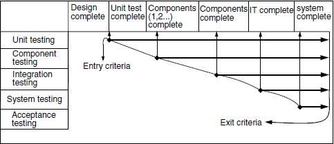
The modified V model recognizes that different parts of a product are in different stages of evolution.
Each part enters the appropriate testing phase (such as unit testing, component testing, and so on) when the appropriate entry criteria are met.
Just as the V Model introduced various types of testing, the modified V model introduces various phases of testing. A phase of testing has a one-to-one mapping to the types of testing, that is, there is a unit-testing phase, component-testing phase, and so on. Once a unit has completed the unit-testing phase, it becomes part of a component and enters the component-testing phase. It then moves to integration-testing phase and so on. Rather than view the product as going through different types of tests (as the V model does), the modified V Model views each part of the product to go through different phases of testing. These are actually two sides of the same coin and thus provide complimentary views. The main advantage the modified V model brings to the table is the recognition of the parallelism present in different parts of the product and assigning each part to the most appropriate phase of testing that is possible. In Figure 2.6, the columns of the table represents one side of V, and rows (which are test phases) represent the other side of V.
In Figure 2.6, notice that different phases of testing are done in parallel. While starting a phase of testing it is important to look at whether the product is ready for testing. It is determined by a set of entry criteria. The earliest possible quality to start the next phase of testing is denoted by entry criteria, and to start the next phase of testing the earlier phase need not have completed. The testing phases are also associated with a set of exit criteria to complete the test activities for each phase. They are determined by exit criteria. The entry and exit criteria for each of the phases ensure that right quality of product delivered for starting the test and right amount of testing is completed for the release. Even though it is indicated in the picture all of the test phases finish at the same time, practically it can have different time lines. The longest phase determines the release date.
In Figure 2.6, there are two additional activities that have not been discussed before. The coloured figure is available on Illustrations. These are “Component (1, 2…) Complete” and “Components Complete”; these are not additional phases in a life cycle. They have been introduced just to denote that integration testing can start after two components have been completed, and when all components are integrated and tested, the next phase of testing, that is, system testing can start.
2.5.6 Comparison of Various Life Cycle Models
As can be seen from the above discussion, each of the models has its advantages and disadvantages. Each of them has applicability in a specific scenario. Each of them also provides different issues, challenges, and opportunities for verification and validation. We summarize in Table 2.3 the salient points about applicability and relevance to verification and validation for each of the models.
Table 2.3 Model applicability and relevance to verification and validation.
| Models | Where Applicable | Relevant Verification and Validation (V & V) Issues |
|---|---|---|
| Waterfall | Where very clearly demarcated phases are present When deliverables of each phase can be frozen beforeproceeding to the next phase |
Testing / V & V postponed by at least one phase
Typically testing is among the most downstream activities
Communication of error (and hence time for correction) can be high |
| Prototyping | Where we have a user (or a product manager) who can give feedback | Provides inbuilt feedback for the requirements
Reuse of prototype (instead of throwing it away) can make verification and validation difficult and may produce undesirable effects |
| RAD | Where we have a user (or a product manager) who can give feedback
When we have CASE and other modeling tools |
Built-in feedback available beyondrequirements also
CASE tools can generate useful documentation that further enhances V & V |
| Spiral | Products evolving as increments
Intermediate checking and correction is possible |
Extends V & V to all increments
Extends V & V to all phases (that is, those beyond requirements gathering as well)
Enables the products to be demonstrated at any phase and enables frequent releases |
| V model | When design of tests can be separated from the actual execution | Early design of tests reduces overall delay by increasing parallelism between development and testingEarly design of tests enables better and more timely validation of individual phases |
| Modified V model | When a product can be broken down into different parts, each of which evolves independently | Parallelism of V model further increased by making each part evolve independently
Further reduces the overall delay by introducing parallelism between testing activities |
The Waterfall Model was initially covered in [ROYC-70]. The origins of the Prototyping Model come from [BROO-75]. The Spiral Model was originally proposed in [BOEH-88]. [GRAD-97] provides some variations to the Spiral Model. [RAME-2002], [PRES-97] and [HUMP-86] provide overviews to all the models.
- Which SDLC model would be most suitable for each of the following scenarios?
- The product is a bespoke product for a specific customer, who is always available to give feedback.
- The same as above, except that we also have access to a CASE tool that generates program code automatically.
- A general purpose product, but with a very strong product marketing team who understand and articulate the overall customer requirements very well.
- A product that is made of a number of features that become available sequentially and incrementally.
- Which of the following products would you say is of “high quality,” based on the criteria we discussed in the book? Justify your answer.
- Three successive versions of the product had respectively 0, 79, and 21 defects reported.
- Three successive versions of the product had respectively 85, 90, and 79 defects reported.
- List three or more challenges from the testing perspective for each of the following models:
- Spiral Model.
- V Model.
- Modified V Model.
- What are some of the challenges that you should expect when moving from the V Model to the Modified V Model?
- Figure 2.1 gave the ETVX Diagram for the design phase of a software project. Draw a similar ETVX Diagram for the coding phase.
- In the book we have discussed the Spiral Model as being ideally suited for a product that evolves in increments. Discuss how the V Model is applicable for such an incrementally evolving product.