
Chapter 5
Integration Testing
In this chapter—
5.1 WHAT IS INTEGRATION TESTING?
A system is made up of multiple components or modules that can comprise hardware and software. Integration is defined as the set of interactions among components. Testing the interaction between the modules and interaction with other systems externally is called integration testing. Integration testing starts when two of the product components are available and ends when all component interfaces have been tested. The final round of integration involving all components is called Final Integration Testing (FIT), or system integration.
Integration testing is both a type of testing and a phase of testing. As integration is defined to be a set of interactions, all defined interactions among the components need to be tested. The architecture and design can give the details of interactions within systems; however, testing the interactions between one system and another system requires a detailed understanding of how they work together. This knowledge of integration (that is, how the system or modules work together) depends on many modules and systems. These diverse modules could have different ways of working when integrated with other systems. This introduces complexity in procedures and in what needs to be done. Recognizing this complexity, a phase in testing is dedicated to test these interactions, resulting in the evolution of a process. This ensuing phase is called the integration testing phase.
Since integration testing is aimed at testing the interactions among the modules, this testing—just like white box, black box, and other types of testing—comes with a set of techniques and methods, which we will see in the following sections. Hence integration testing is also viewed as a type of testing (and thus fits into the canvas of this part of the book).
Integration is both a phase and a type of testing.
In the next section, we will look at integration as a type of testing and in the section thereafter, we will view integration as a phase of testing.
5.2 INTEGRATION TESTING AS A TYPE OF TESTING
Integration testing means testing of interfaces. When we talk about interfaces, there are two types of interfaces that have to be kept in mind for proper integration testing. They are internal interfaces and exported or external interfaces.
Internal interfaces are those that provide communication across two modules within a project or product, internal to the product, and not exposed to the customer or external developers. Exported interfaces are those that are visible outside the product to third party developers and solution providers.
One of the methods of achieving interfaces is by providing Application Programming Interfaces (APIs). APIs enable one module to call another module. The calling module can be internal or external. For example, JDBC is an example of an API used by a Java program to make certain SQL calls. Even though both the API and interfaces appear to be similar, it is important to realize that integration is the purpose to be achieved while API is a means of achieving the purpose. API is just one of the means of providing an interface between two modules. One can think of other means of integration among the various modules: Some of these could be simple function calls, public functions, and some could be facets of programming language constructs like global variables and some could be operating system constructs like semaphares and shared memory. In this chapter, we will not discuss the details of the vehicles used for integration (as it is primarily a development issue), but rather look at how we can test the interfaces (which is the focus for testing).
Not all the interfaces may be available at the same time for testing purposes, as different interfaces are usually developed by different development teams, each having their own schedules. In order to test the interfaces, when the full functionality of the component being introduced is not available, stubs are provided. A stub simulates the interface by providing the appropriate values in the appropriate format as would be provided by the actual component being integrated.
Integration testing is done with test cases, which goes through the internal and exported interfaces, and tests the functionality of the software. Internal interfaces are for other developers inside an organization and external interfaces are for third party developers or other users outside the group. Testing for internal interfaces requires a complete understanding of architecture and high-level design (HLD) and how they impact the software functionality. In cases where exported interfaces are provided from the software, one needs to understand the purpose of those interfaces, why they are provided, and how they are actually used by developers and solution integrators. Hence a knowledge of design, architecture, and usage is a must for integration testing.
Initially, the exported (or external) interfaces were provided through APIs and Software Development Kits (SDKs). The use of SDKs required an understanding of the programming language on which the API/SDK is provided. Later, the interfaces became available through scripting languages, without the need for SDKs. (Some of the popular scripting languages include Perl, Tcl/Tk). These scripting languages eliminated or minimized the effort in learning the languages in which the API was written. This also made it possible for the interfaces to be called from programming language environments different from the one in which the interface was originally written. This significantly simplified the usage of exported interfaces. For testing interfaces, we now have dynamically created scripts, which can be changed at run time, by a few clicks of the mouse.
All these have made the use of interfaces a lot more widespread. The number of purposes for which the interfaces are provided have been on the increase. These interfaces are becoming increasingly generic in nature and not getting tied to a specific application or language. This has resulted in increasing the permutations and combinations of scenarios of usage of the interfaces. Thus, the complexity of integration testing—that is, testing of the various scenarios of usage of interfaces—has also increased significantly.
Integration testing type focuses on testing interfaces that are “implicit and explicit” and “internal and external.”
While discussing about interfaces we need to keep in mind that not all interactions between the modules are known and explained through interfaces. Some of the interfaces are documented and some of them are not. This gives rise to another classification of interfaces, that is, implicit and explicit interfaces. Explicit interfaces are documented interfaces and implicit interfaces are those which are known internally to the software engineers but are not documented. The testing (white box/black box) should look for both implicit and explicit interfaces and test all those interactions.
A question that often arises in the mind of a test engineer is whether integration testing is a black box or a white box testing approach. In most cases, the most appropriate answer is to say integration testing is a black box testing approach. However, in situations where architecture or design documents do not clear by explain all interfaces among components, the approach can include going through the code and generating some additional test cases, and mixing them with other test cases generated using black box testing approaches. This approach could be termed as the “gray box testing” approach.
Let us illustrate this with an example. Figure 5.1 shows a set of modules and the interfaces associated with them. The coloured figure is available on Illustrations. The solid lines represent explicit interfaces and the dotted lines represent implicit interfaces, based on the understanding of architecture, design, or usage.
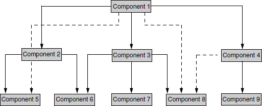
From Figure 5.1 it is clear that there are at least 12 interfaces between the modules to be tested (9 explicit and 3 implicit). Now a question that comes to the mind is in what order do these interfaces need to be tested. There are several methodologies available, to in decide the order for integration testing. These are as follows.
5.2.1 Top-Down Integration
Integration testing involves testing the topmost component interface with other components in same order as you navigate from top to bottom, till you cover all the components.
To understand this methodology better, let us assume, a new product/software development where components become available one after another in the order of component numbers specified in the Figure 5.2. The coloured figure is available on Illustrations. The integration starts with testing the interface between Component 1 and Component 2. To complete the integration testing, all interfaces mentioned in Figure 5.2 covering all the arrows, have to be tested together. The order in which the interfaces are to be tested is depicted in Table 5.1. The coloured format of Table 5.1 is available on Illustrations.
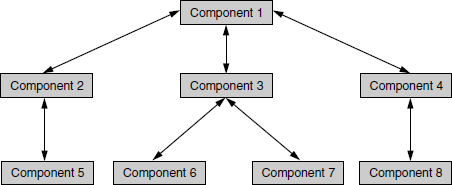
Table 5.1 Order of testing interfaces for the example in Figure 5.2.
| Step | Interfaces tested |
|---|---|
1 |
1-2 |
2 |
1-3 |
3 |
1-4 |
4 |
1-2-5 |
5 |
1-3-6 |
6 |
1-3-6-(3-7) |
7 |
(1-2-5)-(1-3-6-(3-7)) |
8 |
1-4-8 |
9 |
(1-2-5)-(1-3-6-(3-7))-(1-4-8) |
In an incremental product development, where one or two components gets added to the product in each increment, the integration testing methodology pertains to only to those new interfaces that are added and those related interfaces that are impacted by the changes or increment in the product. Therefore, not all the steps in the above table need to be repeated for integration testing in that case. For example, in Figure 5.2 let us assume one component (component 8), is added for the current release; all other components are tested before for the previous release. If that addition has an impact on the functionality of component 5, then integration testing for the current release needs to include only steps 4, 7, 8, and 9.
To optimize the number of steps in integration testing, steps 6 and 7 can be combined and executed as a single step. Similarly, steps 8 and 9 also can be combined and tested in a single step. Combining steps does not a mean reduction in the number of interfaces tested. It just means an optimization in the elapsed time, as we do not have to wait for steps 6 and 8 to get over to start with testing steps 7 and 9 respectively.
If a set of components and their related interfaces can deliver functionality without expecting the presence of other components or with minimal interface requirement in the software/product, then that set of components and their related interfaces is called as a “sub-system.” Each sub-system in a product can work independently with or without other sub-systems. This makes the integration testing easier and enables focus on required interfaces rather than getting worried about each and every combination of components. In Table 5.1, the components pertaining to steps 4, 6, and 8 can be considered as sub-systems.
The top-down integration explanation above assumes that component 1 provides all the interface requirements of other components even while other components are getting ready and does not require modification at a later stage (that is, after the other components have been developed). This approach reflects the Waterfall or V model of software development.
If a component at a higher level requires a modification every time a module gets added to the bottom, then for each component addition integration testing needs to be repeated starting from step 1. This may be a requirement for an iterative model of software development. Hence, whatever may be the software development model, top-down integration can be still applied with appropriate repetition in integration testing.
The order in which the interfaces are tested may change a bit in Figure 5.2 if different methods of traversing are used. A breadth first approach will get you component order such as 1–2, 1–3, 1–4 and so on and a depth first order will get you components such as 1–2–5, 1–3–6, and so on. A breadth first approach was used in Table 5.1 as we have assumed that the components become available in the order of component numbers. But it need not be in the same order for following this integration methodology.
5.2.2 Bottom-up Integration
Bottom-up integration is just the opposite of top-down integration, where the components for a new product development become available in reverse order, starting from the bottom. In Figure 5.3, (coloured figure on Illustrations) the components are assumed to be available in the order of their number.
Figure 5.3 Example of bottom-up integration. Arrows pointing down depict logic flow; arrows pointing up indicate integration paths.
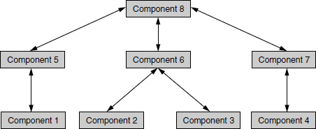
Note: Double arrows in Figure 5.3 denotes both the logical flow of components and integration approach. Logic flow is from top to bottom, and integration path is from bottom to top.
The navigation in bottom-up integration starts from component 1 in Figure 5.3, covering all sub-systems, till component 8 is reached. The order in which the interfaces have to be tested is depicted in Table 5.2.
Table 5.2 Order of interfaces tested using bottom up integration for Figure 5.3.
| Step | Interfaces tested |
|---|---|
1 |
1-5 |
2 |
2-6, 3-6 |
3 |
2-6-(3-6) |
4 |
4-7 |
5 |
1-5-8 |
6 |
2-6-(3-6)-8 |
7 |
4-7-8 |
8 |
(1-5-8)-(2-6-(3-6)-8)-(4-7-8) |
The number of steps in the bottom-up approach can be optimized into four steps, by combining steps 2 and 3 and by combining steps 5–8, as shown in Table 5.2 below. The coloured format is available on Illustrations.
As explained before, in top-down integration, for an incremental product development, only the impacted and added interfaces need to be tested, covering all sub-systems and system components.
One difference between Figure 5.2 and Figure 5.3 is that in the latter the arrows are two-way arrows. The arrows from top to bottom (that is, downward-pointing arrows) indicate interaction or control flow. The arrows from bottom to top (that is, upward-pointing arrows) indicate integration approach or integration path. What it means is that the logic flow of the product can be different from the integration path. While the logic flow or interaction in this case is going from up to down, the integration path is going from down to up. This approach allows a combination of integration approaches to be followed for the same product.
The iterative and agile model is an example to explain the different paths for logic flow and integration approach. In this model, a product development organization needs to demonstrate the product functionalities at regular intervals to customers for getting their feedback. One way to increase the frequency of delivery is to make each of the components independent. Some portion of the code is duplicated across components to demonstrate each of the components separately to the customer. The code duplication is not only for demonstrating the product but also for independent testing. In the above example, components 5-8 are developed as independent components with duplicated common code. After testing and approval from customer, the common code gets pushed into components at a higher level, say to components 5-7. After this iteration, there is still a duplication of this code across components 5-7 which will ultimately get removed by moving the code to component 8, in another iteration. This is one of the evolving models, to make the product complete after several iterations of customer feedback and integration. The interface definitions are done only at the time of moving the code to components at a higher level. The common code moves across components and interface definitions are made only at the time of movement. Hence in this model, each iteration of integration testing starts from step 1 of Table 5.2.
It may be easy to say that top-down integration approach is best suited for the Waterfall and V models and the bottom-up approach for the iterative and agile methodologies. This is only true for the examples taken above, and from a process perspective. In a practical scenario the approach selected for integration depends more on the design and architecture of a product and on associated priorities. Additionally, the selection of a right integration approach needs to consider several other perspectives such as availability of components, technology used, process, testing skills, and resource availability.
5.2.3 Bi-Directional Integration
Bi-directional integration is a combination of the top-down and bottom-up integration approaches used together to derive integration steps.
Look at Figure 5.4. The coloured figure is available on Illustrations. In this example, let us assume the software components become available in the order mentioned by the component numbers. The individual components 1, 2, 3, 4, and 5 are tested separately and bi-directional integration is performed initially with the use of stubs and drivers. Drivers are used to provide upstream connectivity while stubs provide downstream connectivity. A driver is a function which redirects the requests to some other component and stubs simulate the behavior of a missing component. After the functionality of these integrated components are tested, the drivers and stubs are discarded. Once components 6, 7, and 8 become available, the integration methodology then focuses only on those components, as these are the components which need focus and are new. This approach is also called “sandwich integration.”

The steps for integration testing, using this approach is given in Table 5.3. The coloured format is available on Illustrations.
Table 5.3 Steps for integration using sandwich testing.
| Step | Interfaces tested |
|---|---|
1 |
6-2 |
2 |
7-3-4 |
3 |
8-5 |
4 |
(1-6-2)-(1-7-3-4)-(1-8-5) |
As you can see from the table, steps 1–3 use a bottom-up integration approach and step 4 uses a top-down integration approach for this example.
An area where this approach comes in handy is when migrating from a two-tier to a three-tier environment. In the product development phase when a transition happens from two-tier architecture to three-tier architecture, the middle tier (components 6–8) gets created as a set of new components from the code taken from bottom-level applications and top-level services.
5.2.4 System Integration
System integration means that all the components of the system are integrated and tested as a single unit. Integration testing, which is testing of interfaces, can be divided into two types:
- Components or sub-system integration
- Final integration testing or system integration
When looking at steps for each of the above integration methodologies, it is obvious that complete system integration is also covered as the last step. Thus, system integration is actually a part of every methodology described above.
The salient point this testing methodology raises, is that of optimization. Instead of integrating component by component and testing, this approach waits till all components arrive and one round of integration testing is done. This approach is also called big-bang integration. It reduces testing effort and removes duplication in testing.
Big bang integration is ideal for a product where the interfaces are stable with less number of defects.
System integration using the big bang approach is well suited in a product development scenario where the majority of components are already available and stable and very few components get added or modified. In this case, instead of testing component interfaces one by one, it makes sense to integrate all the components at one go and test once, saving effort and time for the multi-step component integrations.
While this approach saves time and effort, it is also not without disadvantages. Some of the important disadvantages that can have a bearing on the release dates and quality of a product are as follows.
- When a failure or defect is encountered during system integration, it is very difficult to locate the problem, to find out in which interface the defect exists. The debug cycle may involve focusing on specific interfaces and testing them again.
- The ownership for correcting the root cause of the defect may be a difficult issue to pinpoint.
- When integration testing happens in the end, the pressure from the approaching release date is very high. This pressure on the engineers may cause them to compromise on the quality of the product.
- A certain component may take an excessive amount of time to be ready. This precludes testing other interfaces and wastes time till the end.
As a result of all these factors, the choice of the method of integration testing becomes extremely crucial. A judicious combination of the above methods would be needed to achieve effectiveness in the time and quality of integration testing.
5.2.5 Choosing Integration Method
Table 5.4 gives some broad level guidelines on selecting the integration method. As mentioned in the above discussions, the integration method depends not only on the process, development model, but also on various other aspects.
Table 5.4 Guidelines on selection of integration method.
S.No. |
Factors | Suggested integration method |
|---|---|---|
1 |
Clear requirements and design | Top-down |
2 |
Dynamically changing requirements, design, architecture | Bottom-up |
3 |
Changing architecture, stable design | Bi-directional |
4 |
Limited changes to existing architecture with less impact | Big bang |
5 |
Combination of above | Select one of the above after careful analysis |
5.3 INTEGRATION TESTING AS A PHASE OF TESTING
As we saw in the beginning of this chapter, integration testing as a phase of testing starts from the point where two components can be tested together, to the point where all the components work together as a complete system delivering system/product functionality. In the integration testing phase, the focus is not only on whether functionality of the components work well, but also on whether they work together and deliver sub-system and system functionality.
The integration testing phase focuses on finding defects which predominantly arise because of combining various components for testing, and should not be focused on for component or few components. Integration testing as a type focuses on testing the interfaces. This is a subset of the integration testing phase. When a sub-system or system components are put together (or integrated), the defects not only arise because of interfaces, but also for various other reasons such as usage, incomplete understanding of product domain, user errors, and so on. Hence the integration testing phase needs to focus on interfaces as well as usage flow. It is very important to note this point to avoid confusion between integration testing type and integration testing phase.
All testing activities that are conducted from the point where two components are integrated to the point where all system components work together, are considered a part of the integration testing phase.
Integration testing as a phase involves different activities and different types of testing have to be done in that phase. This is a testing phase that should ensure completeness and coverage of testing for functionality. To achieve this, the focus should not only be on planned test case execution but also on unplanned testing, which is termed as “ad hoc testing.” As we saw in the chapter, Principles of Testing (Chapter 1), there is no end to testing, and quality cannot depend only on pre-written test cases; ad hoc testing becomes important to integration testing phase. There are different terminologies associated with ad hoc testing, such as exploratory testing, monkey testing, out of the box testing, and so on (Chapter 10). All these tests perform the same functions during integration testing phase, that is, uncover or unearth those defects which are not found by planned test case execution. This approach helps in locating some problems which are difficult to find by test teams but also difficult to imagine in the first place. The approach also helps in generating a comfort feeling on the software and getting an overall acceptance of the product from all internal users of the system.
The integration testing phase involves developing and executing test cases that cover multiple components and functionality. When the functionality of different components are combined and tested together for a sequence of related operations, they are called scenarios. Scenario testing is a planned activity to explore different usage patterns and combine them into test cases called scenario test cases. We will see scenario testing in more detail in the next section.
5.4 SCENARIO TESTING
Scenario testing is defined as a “set of realistic user activities that are used for evaluating the product.” It is also defined as the testing involving customer scenarios.
There are two methods to evolve scenarios.
- System scenarios
- Use-case scenarios/role based scenarios
5.4.1 System Scenarios
System scenario is a method whereby the set of activities used for scenario testing covers several components in the system. The following approaches can be used to develop system scenarios.
Story line Develop a story line that combines various activities of the product that may be executed by an end user. A user enters his or her office, logs into the system, checks mail, responds to some mails, compiles some programs, performs unit testing and so on. All these typical activities carried out in the course of normal work when coined together become a scenario.
Life cycle/state transition Consider an object, derive the different transitions/modifications that happen to the object, and derive scenarios to cover them. For example, in a savings bank account, you can start with opening an account with a certain amount of money, make a deposit, perform a withdrawal, calculate interest, and so on. All these activities are applied to the “money” object, and the different transformations, applied to the “money” object becomes different scenarios.
Deployment/implementation stories from customer Develop a scenario from a known customer deployment/implementation details and create a set of activities by various users in that implementation.
Business verticals Visualize how a product/software will be applied to different verticals and create a set of activities as scenarios to address specific vertical businesses. For example, take the purchasing function. It may be done differently in different verticals like pharmaceuticals, software houses, and government organizations. Visualizing these different types of tests make the product “multi-purpose.”
Battle ground Create some scenarios to justify that “the product works” and some scenarios to “try and break the system” to justify “the product doesn't work.” This adds flavor to the scenarios mentioned above.
The set of scenarios developed will be more effective if the majority of the approaches mentioned above are used in combination, not in isolation. Scenario should not be a set of disjointed activities which have no relation to each other. Any activity in a scenario is always a continuation of the previous activity, and depends on or is impacted by the results of previous activities. Effective scenarios will have a combination of current customer implementation, foreseeing future use of product, and developing ad hoc test cases. Considering only one aspect (current customer usage or future customer requirements, for instance) would make scenarios ineffective. If only current customer usage is considered for testing, new features may not get tested adequately. Considering only the future market for scenarios may make the scenarios test only the new features and some of the existing functionality may not get tested. A right mix of scenarios using the various approaches explained above is very critical for the effectiveness of scenario testing.
Coverage is always a big question with respect to functionality in scenario testing. This testing is not meant to cover different permutations and combinations of features and usage in a product. However, by using a simple technique, some comfort feeling can be generated on the coverage of activities by scenario testing. The following activity table (Table 5.5) explains the concept with an example.
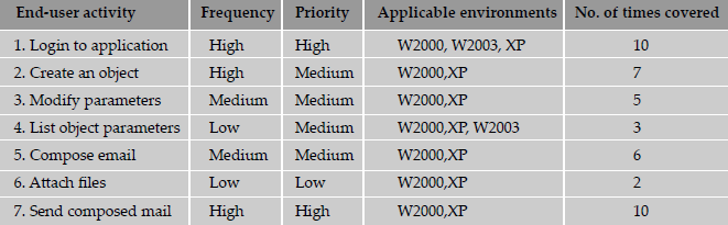
From the table, it is clear that important activities have been very well covered by set of scenarios in the system scenario test. This kind of table also helps us to ensure that all activities are covered according to their frequency of usage in customer place and according to the relative priority assigned based on customer usage.
5.4.2 Use Case Scenarios
A use case scenario is a stepwise procedure on how a user intends to use a system, with different user roles and associated parameters. A use case scenario can include stories, pictures, and deployment details. Use cases are useful for explaining customer problems and how the software can solve those problems without any ambiguity.
A use case can involve several roles or class of users who typically perform different activities based on the role. There are some activities that are common across roles and there are some activities that are very specific and can be performed only by the use belonging to a particular role. Use case scenarios term the users with different roles as actors. What the product should do for a particular activity is termed as system behavior. Users with a specific role to interact between the actors and the system are called agents.
To explain the concept of use case scenarios, let us take the example of withdrawing cash from a bank. A customer fills up a check and gives it to an official in the bank. The official verifies the balance in the account from the computer and gives the required cash to the customer. The customer in this example is the actor, the clerk the agent, and the response given by the computer, which gives the balance in the account, is called the system response. This is depicted in Figure 5.5 The coloured figure is available on Illustrations.

This way of describing different roles in test cases helps in testing the product without getting into the details of the product. In the above example, the actor (who is the customer) need not know what the official is doing and what command he is using to interact with the computer. The actor is only concerned about getting the cash. The agent (who is the official) is not concerned about the logic of how the computer works. He or she is only interested in knowing from the computer whether he or she can give the cash or not. However, the system behavior (computer logic) needs to be tested before applying the sequence of agent activities and actor activities. In this example, the activities performed by the actor and the agent can be tested by testers who do not have much knowledge of the product. Testers who have in-depth knowledge of the product can perform the system behavior part of testing. They need to know the logic of how the code works and whether or not the system response is accurate.
As mentioned earlier, actor and agent are roles that represent different types (classes) of users. Simulating different types of users again needs a clear understanding of business and the system response for each of the user needs a clear understanding of how the product is implemented. Hence, testers using the use case model, with one person testing the actions and other person testing the system response, complement each other's testing as well as testing the business and the implementation aspect of the product at the same time.
The agent part of the use cases are not needed in all cases. In a completely automated system involving the customer and the system, use cases can be written without considering the agent portion. Let us extend the earlier example of cash withdrawal using an ATM. Table 5.6 illustrates how the actor and system response can be described in the use case.
Table 5.6 Actor and system response in use case for ATM cash withdrawal.
| Actor | System response |
|---|---|
| User likes to withdraw cash and inserts the card in the ATM machine | Request for password or Personal Identification Number (PIN) |
| User fills in the password or PIN | Validate the password or PINGive a list containing types of accounts |
| User selects an account type | Ask the user for amount to withdraw |
| User fills in the amount of cash required | Check availability of funds Update account balance Prepare receipt Dispense cash |
| Retrieve cash from ATM | Print receipt |
This way of documenting a scenario and testing makes it simple and also makes it realistic for customer usage. Use cases are not used only for testing. In some product implementations, use cases are prepared prior to the design and coding phases, and they are used as a set of requirements for design and coding phases. All development activities are performed based on use case documentation. In extreme programming models these are termed as user stories and form the basis for architecture/design and coding phases. Hence, use cases are useful in combining the business perspectives and implementation detail and testing them together.
5.5 DEFECT BASH
Defect bash is an ad hoc testing where people performing different roles in an organization test the product together at the same time. This is very popular among application development companies, where the product can be used by people who perform different roles. The testing by all the participants during defect bash is not based on written test cases. What is to be tested is left to an individual's decision and creativity. They can also try some operations which are beyond the product specifications. Defect bash brings together plenty of good practices that are popular in testing industry. They are as follows.
- Enabling people “Cross boundaries and test beyond assigned areas”
- Bringing different people performing different roles together in the organization for testing—“Testing isn't for testers alone”
- Letting everyone in the organization use the product before delivery—“Eat your own dog food”
- Bringing fresh pairs of eyes to uncover new defects—“Fresh eyes have less bias”
- Bringing in people who have different levels of product understanding to test the product together randomly—“Users of software are not same”
- Let testing doesn't wait for lack of/time taken for documentation—“Does testing wait till all documentation is done?”
- Enabling people to say “system works” as well as enabling them to “break the system” — “Testing isn't to conclude the system works or doesn't work”
Even though it is said that defect bash is an ad hoc testing, not all activities of defect bash are unplanned. All the activities in the defect bash are planned activities, except for what to be tested. It involves several steps.
Step 1 Choosing the frequency and duration of defect bash
Step 2 Selecting the right product build
Step 3 Communicating the objective of each defect bash to everyone
Step 4 Setting up and monitoring the lab for defect bash
Step 5 Taking actions and fixing issues
Step 6 Optimizing the effort involved in defect bash
5.5.1 Choosing the Frequency and Duration of Defect Bash
Defect bash is an activity involving a large amount of effort (since it involves large a number of people) and an activity involving huge planning (as is evident from the above steps). Frequent defect bashes will incur low return on investment, and too few defect bashes may not meet the objective of finding all defects. Duration is also an important factor. Optimizing the small duration is a big saving as a large number of people are involved. On the other hand if the duration is small, the amount of testing that is done may not meet the objective.
5.5.2 Selecting the Right Product Build
Since the defect bash involves a large number of people, effort and planning, a good quality build is needed for defect bash. A regression tested build (see Chapter 8) would be ideal as all new features and defect fixes would have been already tested in such a build. An intermediate build where the code functionality is evolving or an untested build will make the purpose and outcome of a defect bash ineffective. Where a large number of people are involved, a good quality product build gives confidence on the product and progress. Also, when testers doing a defect bash uncover an excessive number of defects or very severe defects, the confidence of the testers falls and the perception of the product being unstable lingers on for long.
5.5.3 Communicating the Objective of Defect Bash
Even though defect bash is an ad hoc activity, its purpose and objective have to be very clear. Since defect bash involves people performing different roles, the contribution they make has to be focused towards meeting the purpose and objective of defect bash. The objective should be to find a large number of uncovered defects or finding out system requirements (CPU, memory, disk, and so on) or finding the non-reproducible or random defects, which could be difficult to find through other planned tests. Defects that a test engineer would find easily should not be the objective of a defect bash. Once they are told in advance, the members of defect bash team will be in a better position to contribute towards stated objectives.
5.5.4 Setting Up and Monitoring the Lab
Since defect bashes are planned, short term and resource intensive activities, it makes sense to setup and monitor a laboratory for this purpose. Finding out the right configuration, resources (hardware, software, and set of people to perform defect bash) are activities that have to be planned carefully before a bash actually starts. Since the effort involved is more, it is critical to ensure that the right setup is done, so that everyone can perform the desired set of activities on the software. The majority of defect bash fail due to inadequate hardware, wrong software configurations, and perceptions related to performance and scalability of the software. During defect bash, the product parameters and system resources (CPU, RAM, disk, network) need to be monitored for defects and also corrected so that users can continue to use the system for the complete duration of the defect bash.
There are two types of defects that will emerge during a defect bash. The defects that are in the product, as reported by the users, can be classified as functional defects. Defects that are unearthed while monitoring the system resources, such as memory leak, long turnaround time, missed requests, high impact and utilization of system resources, and so on are called non-functional defects. Defect bash is a unique testing method which can bring out both functional and non-functional defects. However, if the lab is not set up properly or not monitored properly, there is a chance that some of the non-functional defects may not get noticed at all.
5.5.5 Taking Actions and Fixing Issues
The last step, is to take the necessary corrective action after the defect bash. Getting a large number of defects from users is the purpose and also the normal end result from a defect bash. Many defects could be duplicate defects. However, different interpretations of the same defect by different users, and the impact of the same defect showing up differently in different places, make them difficult to be called duplicates. Since there could be a large number of defects, the approach to fix problems from a defect bash should not be at a per defect level. It is difficult to solve all the problems if they are taken one by one and fixed in code. The defects need to be classified into issues at a higher level, so that a similar outcome can be avoided in future defect bashes. There could be one defect associated with an issue and there could be several defects that can be called as an issue. An example of an issue can be “In all components, all inputs for employee number have to be validated before using them in business logic.” This enables all defects from different components to be grouped and classified as one issue. All the issues reported from a defect bash need to be taken through a complete code and design inspections, analyzed, and fixed together in places where a defect could evolve from. So the outcome of a defect bash can also be used for preventing defects for future defect bashes.
5.5.6 Optimizing the Effort Involved in Defect Bash
Since a defect bash involves a large number of people, spending much effort is normal for conducting defect bashes. There are several ways to optimize the effort involved in a defect bash if a record of objectives and outcome is kept. Having a tested build, keeping the right setup, sharing the objectives, and so on, to save effort and meet the purpose have been already discussed. Another approach to reduce the defect bash effort is to conduct “micro level” defect bashes before conducting one on a large scale. Some of the more evident defects will emerge at micro level bashes.
Since a defect bash is an integration testing phase activity, it can be experimented by integration test team before they open it up for others. To prevent component level defects emerging during integration testing, a micro level defect bash can also be done to unearth feature level defects, before the product can be taken into integration. Hence, a defect bash can be further classified into
- Feature/component defect bash
- Integration defect bash
- Product defect bash
To explain the effort saved by the defect bash classification, let us take three product defect bashes conducted in two hours with 100 people. The total effort involved is 3*2*100=600 person hours. If the feature/component test team and integration test team, that has 10 people each, can participate in doing two rounds of micro level bashes, which can find out one third of defects that are expected, then effort saving is 20% with respect to the following calculation.
Total effort involved in two rounds of product bashes—400 man hours
Effort involved in two rounds of feature bash (2*2*10)—40
Effort involved in two rounds of integration bash (2*2*10)—40
Effort saved = 600 - (A + B + C) = 600 - 480 = 120 person hours, or 20%
This is only an approximate calculation, as the effort involved in the steps mentioned earlier in this section (Steps 1–6) also need to be included for each defect bash. Those steps have to be repeated for each defect bash, irrespective of whether they are at feature level or integration level or product level.
A defect bash is an ad hoc testing, done by people performing different roles in the same time duration during the integration testing phase, to bring out all types of defects that may have been left out by planned testing.
5.6 CONCLUSION
Integration testing is both a type of testing and a phase of testing. Integration testing starts after each of the components are tested alone and delivered, using black box testing approaches discussed in Chapter 4. All components tested and working do not mean they will continue to work the same way after they are put together and integrated. This is an important phase/type of testing that is often ignored by many organizations. Owing to project pressure and delay in development schedules, integration testing may get diluted as it is performed in between component and system testing phases. A separate test team focusing on integration testing is an initiative recently taken by several companies to provide to integration testing the focus it has deserved for a long time. Integration testing, if done properly, can reduce the number of defects that will be found in the system testing phase, a phase that is explained in the following chapter.
[MYER-79] is one of the earliest comparisons of the various integration approaches. [YEWU-2001] also provides a good reference for different approaches to integration testing.
- For each of the systems characterized by the descriptions below, decide which type of integration is best suited for testing
- A product is evolving in versions and each version introduces new features that are fairly insulated from other features, i.e., the existing features are stable and do not get affected much by the additions
- A product is made of components with clearly defined interfaces. Hence, the stubs and drivers are available right from day one.
- A product provides standard database query and display facilities. The query facility implements standard JDBC interfaces, while the display facility provides flexibility to interface multiple platforms and display systems (like Windows, Macintosh, etc)
- Consider a typical university academic information system. Identify the typical agents, actors, and the expected system behavior for the various types of use cases in this system
- Consider a product which evolves is versions, each version taking approximately six months to release to the market. When would you initiate each type of defect bash for a version? Clearly state the assumptions you made while making that decision.
- Which of the approaches given in the text would you use to arrive at system scenarios for the following cases:
- A customer recounts, “During the last version implementation, I had difficulty in migrating data from the previous version -it failed while backing up data for the customer master and while adding extra columns for the discounts table.”
- A product is being deployed in the FMCG industry and in the retail sales industry and should be customizable to each.
- A test engineer performs unit testing, updates the defect repositories, sends emails to the components owners, chats with them and updates his log.
- Give examples to show cases where integration testing can be taken as a white box approach (i.e., with access to code) and to show cases where it can be taken as a black box approach (i.e., no access to code).