
Chapter 20
LIGHT IN THE CITY

With such particles suspended in the atmosphere for sometimes days or weeks at a time, smog presents a danger to health, but in London it was also known as a “pea souper” because one could not see one’s hand in front of one’s face! In fact, as a result of the Great London Smog of 1952 (caused by the smoke from millions of chimneys combined with the mists and fogs of the Thames valley), the Clean Air Act of 1956 was enacted. With this in mind we now turn to the topic of how air pollution may affect visibility.
X = Is: VISIBILITY IN THE CITY
We start with an apparent non sequitur by asking the following question. Have you ever been in an auditorium of some kind, or a church, in which your view of a speaker is blocked by a pillar, but you can still hear what is being said? I’m pretty sure you must have experienced this. Why can your ears receive auditory signals, but your eyes cannot receive direct visual ones (excluding Superman of course)? The reason for this is related to the wavelengths of the sound and light waves, being ≈1m and ≈5 × 10⁻⁷ m, respectively. The latter, in effect, “scatter” more like particles while the former are able to diffract (“bend”) around an obstacle comparable in size to their wavelength. By the same token, therefore, we would expect that light waves can diffract around appropriately smaller obstacles, and indeed this is the case, as evidenced by softly colored rings of light around the moon (coronae) as thin cloud scuds past its face. Another diffraction-induced meteorological phenomenon is the green, purple-red, or blue iridescence occasionally visible in clouds. But it is the collective phenomenon known as scattering that we wish to discuss in some detail, in order to better appreciate the character of air pollution and its effect on the light that reaches our eyes.
So: when light is deflected in some manner from its direction of travel, it is said to be scattered. There are several mechanisms that contribute to the scattering of light by particles in the atmosphere: reflection, refraction, and diffraction being the most common, though they are not necessarily mutually exclusive effects. The size of the particles determines which mechanism is the predominant one.
Visibility is reduced to some extent by the absorption of light, but scattering by particles and droplets is the primary source of this reduction. We perceive distant objects by contrast with their environment, and this contrast is reduced by the scattering of light from particles and droplets in the line of sight. Thus visibility is reduced. Depending on their size, particles may settle out of the air in due course; this sedimentation process had already been mentioned in the previous chapter.
Although the particles will be irregular in shape, we can define an effective radius as the average of that of (i) the largest sphere that can be inscribed in the particle and (ii) the smallest sphere that contains the particle. If this radius exceeds about 10 microns (10−5 m), they settle out in several hours. As we saw, when an object falls in air, it is subject to at least two separate forces; its weight (acting downward) and air resistance or drag (acting upward). A third force is that of buoyancy (also acting upward), but since the air density is negligible compared with that of the particle, this can be neglected. The particle weight is proportional to its mass and hence to the cube of its radius. As we saw in the previous chapter, the air resistance is only proportional to its radius, so the weight dominates the drag by a factor that increases as the square of the radius; hence larger particles fall faster, at least initially. As the speed increases, so does the air resistance. If the particle falls from a sufficient height, these competing forces eventually balance each other, and the net force is zero. At this point the particle falls with a constant speed, the terminal speed. On the other hand, if the particles are smaller than 10 microns in size, they can remain suspended in the air for several days, buffeted by air currents.
This, then, is a qualitative summary of the hydrodynamic aspects of sedimentation discussed earlier. By contrast, the optical aspects are more complicated because of the range of particle sizes compared with the wavelengths of visible light (approximately 0.4–0.7μ) A convenient measure of relative size is the radius-to-wavelength ratio R/λ. When this ratio is at least about ten, the particles are considered to be large, and it is convenient to regard light in terms of rays. This is the domain of geometrical optics, and as illustrated in Figure 20.1, the three processes mentioned above can occur. Light rays can be partially reflected from the surface of the particles, refracted on passing through the interior, or diffracted (“bent”) around the edges. All three mechanisms are exhibited in the phenomenon of the rainbow (see Appendix 11); light is refracted and reflected by raindrops to produce this beautiful colored arc in the sky. Less familiar is the third important mechanism—diffraction—a consequence of the wavelike properties of light. This is responsible for some of the more subtle rainbow features—pale fringes below the top of the bow and, as already noted, iridescence in clouds near the sun.
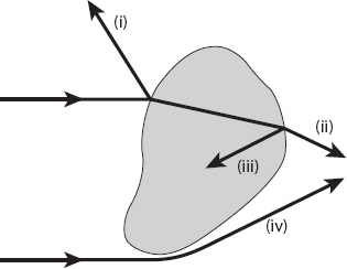
Figure 20.1. Light incident on a large particle may undergo some or all of the indicated processes: (i) reflection at the surface; (ii) refraction into and out of the particle; (iii) internal reflection; and (iv) edge diffraction. Redrawn from Williamson (1973).
For large particles, the amount of light “scattered” by diffraction is as much as that by the other two mechanisms. Some of the refracted light may be absorbed by the particles; if so, this will affect the color of the outgoing radiation. An extreme example of this is black smoke—in this case most of the incident radiation is absorbed. When little or no absorption occurs, large particles scatter light pretty much in the forward direction, so the observer looking toward the light source—the sun, usually—will see a general whitish color. When the particles are not large, the “light ray” approach of geometrical optics is inadequate to describe the scattering processes; the wave nature of light, as mentioned above, must be taken into account. Particles for which R/λ ≈ 1 scatter light in a wider “band” away from the incident direction (resulting in the sky appearing hazy), but smaller particles (for which R/λ ![]() 1) are better able to scatter light multidirectionally. If the aerosols are smaller than about 0.1 μ, the light is scattered much more uniformly in all directions; as much backward as forward and not much less off to the sides. Furthermore, the amount of scattering is very sensitive to the wavelength of the incident light; as we will see below the degree of scattering is ∝ λ−4. This means that the light of shorter wavelength, such as blue or violet, is scattered much more than the longer wavelength red light. Only when we look in the direction of the setting sun, for example, do we see the red light predominating—most of the blue has been scattered out of the line of sight. Think for a moment of cigarette smoke curling upward from an ashtray; typically it is bluish in color—a consequence of the smoke particles being smaller than the wavelengths of light. It is the blue light that is scattered more, and this is what we see.* This is an example of Rayleigh scattering, the same phenomenon that makes the sky blue. Rayleigh scattering arises because of wavelength-dependent molecular scattering
1) are better able to scatter light multidirectionally. If the aerosols are smaller than about 0.1 μ, the light is scattered much more uniformly in all directions; as much backward as forward and not much less off to the sides. Furthermore, the amount of scattering is very sensitive to the wavelength of the incident light; as we will see below the degree of scattering is ∝ λ−4. This means that the light of shorter wavelength, such as blue or violet, is scattered much more than the longer wavelength red light. Only when we look in the direction of the setting sun, for example, do we see the red light predominating—most of the blue has been scattered out of the line of sight. Think for a moment of cigarette smoke curling upward from an ashtray; typically it is bluish in color—a consequence of the smoke particles being smaller than the wavelengths of light. It is the blue light that is scattered more, and this is what we see.* This is an example of Rayleigh scattering, the same phenomenon that makes the sky blue. Rayleigh scattering arises because of wavelength-dependent molecular scattering
To understand the phenomenon of scattering from a more analytic point of view, we need to recall some basic physics. An electromagnetic wave has, not surprisingly, both an electric and a magnetic field that are functions of time and space as it propagates. The direction of propagation and the directions of these fields form a mutually orthogonal triad (Figure 20.2). And when an electromagnetic field encounters an electron bound to a molecule, the electron is accelerated by the electric field of the wave. It’s a type of “chicken and egg” situation, because an accelerated electron will also radiate electromagnetic energy in the form of waves in all directions (to some extent), and this is the scattered radiation that we have been discussing. Consider Figure 20.3, which illustrates such a situation for a small particle with R/λ ![]() 1 as a snapshot in time.
1 as a snapshot in time.
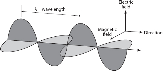
Figure 20.2. Orthogonal triad formed by the direction of the electric and magnetic fields and the direction of propagation for an electromagnetic wave.
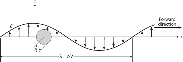
Figure 20.3. A spherical particle of radius R ![]() λ experiences a nearly constant electric field E. (The wavelength of the incident light is λ.) Redrawn from Williamson (1973).
λ experiences a nearly constant electric field E. (The wavelength of the incident light is λ.) Redrawn from Williamson (1973).
As shown in the figures, the wave propagates with speed c in the x-direction, with the electric field in the z-direction (it is said to be polarized in that direction; this is a qualification we shall address below). This field varies periodically with frequency, ![]() = c/λ (where λ is the wavelength), and its fluctuations affect the electrons it encounters. To a much lesser extent, the more massive nuclei are also affected, but this will be ignored here. We shall denote the incident electric field by
= c/λ (where λ is the wavelength), and its fluctuations affect the electrons it encounters. To a much lesser extent, the more massive nuclei are also affected, but this will be ignored here. We shall denote the incident electric field by
![]()
where x0 is the location of this particular electron on the x-axis, E0 is the amplitude of the wave, and ω = 2π![]() is called the angular frequency of the wave. As the wave passes, electrons will be accelerated back and forth in the z-direction, which in turn will radiate electromagnetic waves—this radiation is the scattered light. An important consequence of our assumption that the particle is small is this: since R
is called the angular frequency of the wave. As the wave passes, electrons will be accelerated back and forth in the z-direction, which in turn will radiate electromagnetic waves—this radiation is the scattered light. An important consequence of our assumption that the particle is small is this: since R ![]() λ the electric field is almost uniform throughout the particle, so every electron (with charge e) experiences close to the same force (eE) accelerating it, proportional to its displacement s from its former position of equilibrium in the absence of the wave. The force will always be such as to move the electron back toward that position, so it can be incorporated in Newton’s second law of motion as follows:
λ the electric field is almost uniform throughout the particle, so every electron (with charge e) experiences close to the same force (eE) accelerating it, proportional to its displacement s from its former position of equilibrium in the absence of the wave. The force will always be such as to move the electron back toward that position, so it can be incorporated in Newton’s second law of motion as follows:
![]()
m being the electron mass, a being its acceleration, and A being a constant of proportionality. This is recognizable as an inhomogeneous second-order differential equation with constant coefficients. It is in fact the equation of forced simple harmonic motion.
Exercise: Show that the solution s(t) to equation (20.2), satisfying the simplest initial conditions s(0) = 0 and s′(0) = 0, is given by
![]()
provided that A ≠ mω2. In the event that these quantities are equal—a case known as resonance, which will not be pursued here—the solution can be found directly from the original differential equation or by applying L’Hôpital’s rule to the solution (20.3).
Exercise: Show that the solution for s(t) when A = mω2 is given by
![]()
Returning to equation (20.3), we note that, because of the “tight binding” of electrons in most aerosols, the term ![]() so the second term usually can be neglected. Then the electron acceleration can be approximated by the expression
so the second term usually can be neglected. Then the electron acceleration can be approximated by the expression
![]()
The amplitude of this acceleration is proportional to ω2E0. Recall that the electric field (and hence acceleration of the electron) is perpendicular to the direction of the incident wave. Reversing this, we anticipate that the electric field of the scattered wave will be proportional to the perpendicular component of the acceleration at large distances from the particle, that is, to a sin θz, where θz is the angle between the direction of the scattered light and the z-axis (see Figure 20.4), which is the direction of the incident electric field. We also expect that the total electric field is proportional to the number of electrons present in the particle, and therefore to its volume V. The intensity Is of this scattered light is proportional to the square of the electric field, and allowing for the usual inverse square fall-off with distance r, consistent with energy conservation, we arrive at the proportionality relation
![]()
where ![]() . The scattered wave makes an angle θx = π/2 − θz with the forward direction (x-axis). We have therefore obtained a fundamental result for Rayleigh scattering, namely that the intensity of scattered light is inversely proportional to the fourth power of the wavelength. More accurately, the probability that a photon of sunlight will be scattered from its original direction by an “air molecule” is ∝ λ−4. In any case, a higher proportion of blue light (λ ≈ 0.4μ) than red light (λ ≈ 0.7μ) is scattered, in fact about (7/4)4 ≈ 9 times more.
. The scattered wave makes an angle θx = π/2 − θz with the forward direction (x-axis). We have therefore obtained a fundamental result for Rayleigh scattering, namely that the intensity of scattered light is inversely proportional to the fourth power of the wavelength. More accurately, the probability that a photon of sunlight will be scattered from its original direction by an “air molecule” is ∝ λ−4. In any case, a higher proportion of blue light (λ ≈ 0.4μ) than red light (λ ≈ 0.7μ) is scattered, in fact about (7/4)4 ≈ 9 times more.
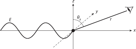
Figure 20.4. Light is scattered from a particle at the origin in a direction that makes an angle θz with respect to the z-axis. The observation distance is r.
There are some other things to note from this formula. The scattered radiation is proportional to V2; this results of course in a reduction of intensity in the forward direction. Note that the dependence on V2 corresponds to one on the sixth power of radius R. This dependence on V can be contrasted with intensity reduction arising from absorption within the particle. The latter will be proportional to the number of absorbing molecules present, and therefore to V. Therefore, in relative terms the importance of scattering (as opposed to absorption) for intensity reduction in the forward direction will be greater for larger particles (still satisfying the requirement that R/λ ![]() 1). Also it is clear that the intensity of scattered light depends on the angle θz, but remember, this is for the special case of polarized light. For scattering in the x-y plane, there is no angular dependence because of symmetry about the z-axis, and so for this case.
1). Also it is clear that the intensity of scattered light depends on the angle θz, but remember, this is for the special case of polarized light. For scattering in the x-y plane, there is no angular dependence because of symmetry about the z-axis, and so for this case.
![]()
Sunlight is unpolarized [35] because the electric field in light from the sun vibrates in all possible directions. We can use the existing result (20.6) and generalize it to this case as follows. We define the scattering plane to be the plane containing both the forward and scattered directions. An unpolarized incident wave can be written as the arithmetic mean of two independent linearly polarized components, one parallel to and the other perpendicular to the scattering plane. Essentially, to do this we average the scattered intensity by replacing the term sin2θz by (sin2θz + sin2θy)/2, where θy is the angle the direction of observation makes with the y-axis. By including the corresponding angle with the x-axis, we note that the squares of the direction cosines sum to one, that is,
![]()
This is equivalent to
![]()
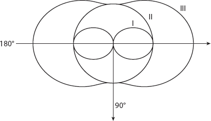
Figure 20.5. Angular variation of the polarization intensity components for the scattered light. The central curve, I, represents the component ![]() as given by equation (20.6); curve II is for the component
as given by equation (20.6); curve II is for the component ![]() as given by equation (20.7); and curve III is for the total intensity polarization,
as given by equation (20.7); and curve III is for the total intensity polarization, ![]() , as given by equation (20.8). The forward direction is θx = 0°.
, as given by equation (20.8). The forward direction is θx = 0°.
Therefore in total
![]()
for unpolarized sunlight. This total scattering intensity is just the sum of the two polarization intensities. This is illustrated in Figure 20.5. The perpendicular component of polarization (![]() ) is the central figure, the middle figure is the parallel component (
) is the central figure, the middle figure is the parallel component (![]() ), independent of angle because this is scattering in the x-y plane, perpendicular to the electric field vector), and the outer figure (
), independent of angle because this is scattering in the x-y plane, perpendicular to the electric field vector), and the outer figure (![]() ) is the sum of these two. Therefore the scattered light is most polarized (and least bright) perpendicular to the incoming light, and least polarized (and most bright) in the forward and backward directions.
) is the sum of these two. Therefore the scattered light is most polarized (and least bright) perpendicular to the incoming light, and least polarized (and most bright) in the forward and backward directions.
The angular dependence of the polarization for unpolarized incident light is conveniently expressed in terms of the quotient
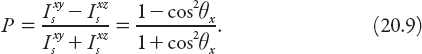
The graph of P is shown in Figure 20.6 (in Cartesian form with θx in radians), illustrating afresh that (for ideal molecular scatterers) the light is 100% polarized at 90° to the incoming radiation and completely unpolarized in the forward (0°) and backward (180°) directions. (In practice this will not be the case because molecules are not perfect scatterers [36].)
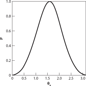
Figure 20.6. Degree of polarization for unpolarized incident light as given by equation (20.9).
We have stated that the results above for Rayleigh scattering apply when the particle size is much less than the wavelength of incident light, that is, R/λ ![]() 1. But what does the phrase “much less” really mean? There is no universal definition, and as usual, it depends on the context. Several books and articles on the topic of scattering use the inequality R < λ/20, or even R < λ/10, and we shall be content with this. Since the wavelength of visible light lies in the range 400–800 nm (0.4μ–0.8μ), this means that R < 0.04μ should suffice.
1. But what does the phrase “much less” really mean? There is no universal definition, and as usual, it depends on the context. Several books and articles on the topic of scattering use the inequality R < λ/20, or even R < λ/10, and we shall be content with this. Since the wavelength of visible light lies in the range 400–800 nm (0.4μ–0.8μ), this means that R < 0.04μ should suffice.
For particles larger than this the processes of reflection, refraction, and diffraction cannot be neglected. It turns out that most of the light is scattered near the forward direction, but for particles whose size is comparable with the wavelengths of light, the situation is quite complex (but very interesting!) both mathematically and physically. The exact solution to this problem for spherical particles is often referred to as the Mie solution, from a 1908 paper by Gustav Mie; Debye also solved the problem independently in 1909, but the solution had already been published in 1863 by Clebsch, and again independently by Lorenz in 1890 and 1898. The rediscovery of existing results is a rather common theme in the history of science and mathematics.
The total amount of light scattered by a spherical particle is quite sensitively dependent on R/λ as already noted. This dependence can be characterized by a quantity Cs, the scattering area coefficient. It is defined to be the amount of light that would be intercepted by a particle (not necessarily a sphere) of cross-sectional area CsπR2. If, for example, the particles are very small, that is, R/λ ![]() 1, the dominating mechanism is Rayleigh scattering, with its dependence on R6 (or V2, see equation (20.8)), then Cs will increase as (R/λ)4 initially. For scattering by sufficiently large particles, Cs approaches two. This is the source of a fascinating paradox, the extinction paradox: why is Cs not equal to one? The debate involves some very sophisticated mathematical physics that will not be discussed here except to say that it involves interactions between the external and internal radiation fields of the particle. However, it should be pointed out that the paradox has not been entirely resolved if recent literature on the topic is anything to go by!
1, the dominating mechanism is Rayleigh scattering, with its dependence on R6 (or V2, see equation (20.8)), then Cs will increase as (R/λ)4 initially. For scattering by sufficiently large particles, Cs approaches two. This is the source of a fascinating paradox, the extinction paradox: why is Cs not equal to one? The debate involves some very sophisticated mathematical physics that will not be discussed here except to say that it involves interactions between the external and internal radiation fields of the particle. However, it should be pointed out that the paradox has not been entirely resolved if recent literature on the topic is anything to go by!
Figure 20.7 shows a graph of Cs vs. 2πR/λ (the ratio of circumference to wavelength) for a spherical particle with the same density as water. As noted above, Cs rises toward its first (and largest) maximum, it does so initially as the power function (2πR/λ)4. This rapid increase in scattering “efficiency” reaches a maximum when R/λ ≈ 6.3/2π ≈ 1. Recall that the Rayleigh scattering formula was derived assuming R/λ is small. For large enough particles the electric field within it is no longer approximately uniform, and this detracts from the cumulative effect for smaller ones, leading to a dramatic decline in Cs. The subsequent oscillatory behavior is a consequence of the particle size periodically meeting the requirements for destructive and constructive interference of the electric field within it.
Figure 20.7. Dependence of the coefficient Cs on the ratio 2πR/λ for a spherical particle with refractive index equal to that of water, that is, ≈ 4/3. (The incident light is assumed to be monochromatic for simplicity.) Redrawn from Williamson (1973).
Consider the graph on the left side of the first maximum, say 0 < 2πR/λ < 4π ≈ 12.6, and suppose that R is fixed. Then for longer wavelengths, corresponding to orange or red light, the scattering (as measured by Cs) is less than for shorter wavelengths, such as in blue or violet light, for that size particle (because Cs increases as R/λ increases). Now we let R be a somewhat larger (but still fixed) value corresponding to the decreasing part of the graph after the first maximum. This time the scattering efficiency is reversed: Cs decreases as λ decreases. It should be apparent that, given a suitable size distribution of particles—such as those from forest fires or volcanic eruptions—the sun or moon may appear strangely colored—blue moons and even green ones have been reported [36].
While the amount of light scattered by a particle is of theoretical interest, the amount scattered by a given mass concentration of particles is of more direct interest in gauging the effects of air pollution. For simplicity, we consider the particles to be of uniform size and density ρ. Then the mass of each particle is m = 4πρR/3. If M is the particle mass concentration (the mass of pollutant per unit volume, for example, c mg/m3), then a cylinder of cross-sectional area 1 m2 will contain M/m = 3M/4πρR3 particles for every meter of its length. Multiplying this number by the effective particle cross-sectional area CsπR2 gives a relative measure of the amount f of the incident beam that is scattered, that is,
![]()
for a given wavelength of light. Figure 20.8 shows a graph of this ratio denoted by ![]() ; valid for any prescribed wavelength, it shows how scattering of light for a given mass concentration is most efficient when the wavelength of light is close to the particle size, that is, λ ≈ R.
; valid for any prescribed wavelength, it shows how scattering of light for a given mass concentration is most efficient when the wavelength of light is close to the particle size, that is, λ ≈ R.
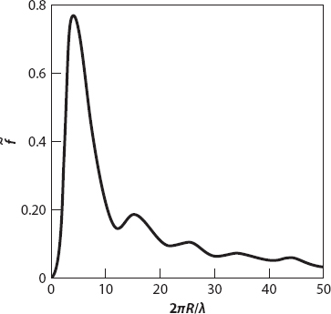
Figure 20.8. Dependence of the relative scattering coefficient ![]() on the ratio 2πR/λ for a spherical particle with refractive index ≈4/3. Redrawn from Williamson (1973).
on the ratio 2πR/λ for a spherical particle with refractive index ≈4/3. Redrawn from Williamson (1973).
X = xB: RAINBOWS AND “ROADBOWS” IN THE CITY
We are familiar with rainbows and, perhaps to a lesser extent, with atmospheric halos formed during the day when (very nearly) parallel light from the sun is “scattered” into the observer’s eye by raindrops and ice crystals, respectively. The drops or crystals producing the phenomena are located on the surface of an apparent cone; in the case of the rainbow the axis extends from the observer’s eye toward the so-called anti-solar point (i.e., extending to the shadow of the observer’s head and beyond) as shown in Figure 20.9. In the case of, say, the common 22° ice crystal halo (Figure 20.10), the axis of the cone extends in a direction from the observer’s eye to the sun.
The reader is encouraged to consult Appendix 11 if he or she needs to brush up on the basic mathematics behind the formation of these beautiful images.
But have you ever noticed a rainbow-like reflection from a road sign when you walk or drive by it during the day? Tiny, highly reflective spheres are used in road signs, sometimes mixed in paint, or sometimes sprayed on the sign. And sometimes, after a new sign has been erected, quantities of such “microspheres” can be found on the road [37] near the sign. It is possible to get samples of these tiny spheres directly from the manufacturers, and reproduce some of the reflective phenomena associated with them. In particular, for glass spheres with refractive index n ≈ 1.51 scattered uniformly over a dark matte plane surface, a small bright penlight provides the opportunity to see a beautiful near-circular bow with angular radius about 22°! (Don’t confuse this with the 22° ice crystal halo; again, see Appendix 11.) This bow appears to be suspended above the plane as a result of the stereoscopic effects we now proceed to examine.
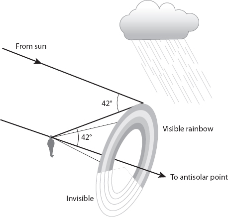
Figure 20.9. Formation of a (primary) rainbow.
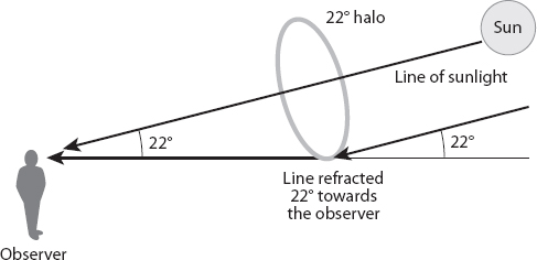
Figure 20.10. Formation of the common 22° ice crystal halo.
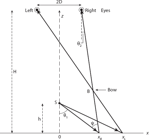
Figure 20.11. Geometry for the “microsphere” bow.
In Figure 20.11, representing the x-z plane, the (point) source of light is at the point S(0, 0, h) and the observer’s right (R) and left (L) eyes, aligned along the x-axis, are located at (±D, 0, H), respectively, where H > h. The intersection of the bow with this plane is at the point B(xB, 0, zB). The ray path SxRR corresponds to a deviation of δ = 180° − (θ1 − θ2) from the original direction. It is an interesting exercise to show that for a sphere of refractive index n this deviation is
![]()
For n ≈ 1.51. δ ≈ 2.76 radians, or approximately 158°.
Exercise: Use equations (A11.3) and (A.11.4) in Appendix 11 to establish the result in equation (20.11). (The angle δ here is D(ic) in equation (A11.4).)
We shall work with the angle ψ = θ1 − θ2 ≈ 22° in what follows. From Figure 20.8 we note that
![]()
Similarly, for the left eye,
![]()
After some rearrangement it follows that
![]()
The resulting quadratic equation for the location of xR is
![]()
All the coefficients in this equation are known, or in principle measurable, so an explicit analytic expression for xR can be obtained. However, care is required in choosing the correct root, since xR must be unique; it is therefore probably better to solve (20.12) directly instead. By changing the sign of D in both these equations we can obtain those for xL also.
Using similar triangles, points (x, z) on the line RxR satisfy the equation
![]()
and, changing the sign of D for xL on the line LxL,
![]()
Since these two lines intersect at the perceived bow, the point B, we can equate the two expressions and solve for x = xB. Thus we find
and substituting this value into either of the equations (20.16) or (20.17), we obtain
![]()
Note that, from equations (20.12) and (20.13), both xL and xR are functions of h, H, and D.
Regarding the shape of the bow, for an observer directly over the light source it may appear to be exactly circular because of the bilateral symmetry of the human face. In the above scenario the eyes are separated by a distance 2D along the x-axis, but have no separation in the y-direction. Obviously, if D → 0 the shape will approach that of a circle, but of course the stereoscopic effect will also disappear (and we would lose an eye!). If D were to increase, the bow would become more ellipse-like. In practice, for most observers the departure from a circular shape will be small unless the eyes are not above the light source, in which case the bow has an ellipse-like shape, and appears tilted relative to the x-y plane. (See Crawford 1988.)
* But note that, if the smoke is exhaled, it appears to be whiter because moisture from the air in the lungs has coated the smoke particles. This increases their effective size, and alters the wavelength dependence of the scattering. Light is now scattered more uniformly than before, and hence the smoke appears whiter.