ZBrush and Working with Imported Meshes
In ZBrush, models are 3D meshes that are imported into ZBrush to become ZTools. The difference between ZTools and models is that a model is just a 3D mesh file that contains polygons and UV information. A ZTool is ZBrush’s native file format for sculpted objects. A ZTool can contain multiple levels of subdivision, high-resolution sculpting details, texture, and polypaint information, as well as alpha maps and layer data. The ZTool format allows you to store far more than just an OBJ file.
Models are imported into the Tool palette where they become available with the other ZTools listed there. When importing models into the Tool palette, it is important to be sure your mesh is optimized for detailing in ZBrush. If your mesh is ordered and animation ready, or is part of an existing production pipeline, you may not have the freedom to lower the initial polygon count. The edge flows and topology have already been approved for rigging and animation. When loading a model into ZBrush, you must understand how ZBrush determines subdivisions levels and where the system limits are.
Physical memory is the most important deciding factor in determining your highest subdivision level, followed closely by processor speed. ZBrush is not concerned with graphics cards, and multiple processors are only useful when moving the model around the screen and sculpting. ZBrush uses the amount of physical RAM installed on the system to determine the highest possible subdivision level attainable. The processor comes into play when you start to rotate and manipulate the sculpture onscreen. A faster processor will allow you to move more polygons with less lag.
You can find the maximum subdivision level that ZBrush has set for the machine by choosing Preferences Mem. The MaxPolyPerMesh slider will show the value in terms of millions. A value of 20 here means that ZBrush will only allow you to subdivide to 20 million polygons (Figure 3-1). As shown in Chapter 1, “Sculpting, from Traditional to Digital,” it is possible to raise this value, but it is not always recommended as it can cause instability. If you raise the MaxPolyPerMesh value slider, be sure to raise the CompactMem slider to 256, 2048, or 4096. Doing so increases the amount of memory ZBrush will use before starting to write temp files to the hard drive, which slows down performance.
Figure 3-1: The Mem preferences

The question arises of how to ensure you get the maximum subdivision levels from ZBrush. Often an artist will load a mesh for sculpting only to find that it subdivides to a level that is unsatisfactory to get the level of detail desired. Starting with a lower polygon count can help ensure you reach the highest possible subdivision level. This approach works because of the algorithm ZBrush uses to subdivide.
ZBrush uses Catmull–Clark subdivision each time you click the Divide button. This means that for each subdivision level, ZBrush multiplies the total polygon count by 4. So if level 1 is 4,000 faces, level 2 will be 4,000 x 4. That gives you a level 2 poly count of 16,000. If this mesh were divided again, ZBrush would multiply 16,000 by 4, giving you a level 3 polygon count of 64,000. If your initial poly count at level 1 were 17,000, you would reach 1 million faces by three subdivisions. Unless you set your MaxPolyPerMesh slider to something above 4, you would not subdivide again as the fourth subdivision level would be over 4 million.
Underlying topology can become a concern in ZBrush if your edge loops define forms that you choose to change later. There are times where your topology may fight the forms you are trying to make. Because of this, simple block models can be beneficial when working in ZBrush. They offer extremely simple bases that can be moved at the lower subdivision levels easily as well as subdivided up to millions of polygons for fine detailing. Once the sculpture is completed, these meshes can easily be retopologized to any mesh resolution you desire. This helps keep the sculpting process separate from polygon modeling and allows you to focus on topology and technical concerns after the design phase is completed. The leg in Figure 3-2 illustrates how much form can be pulled from a simple block model. Figure 3-3 illustrates just how little underlying topology is required to create a detailed character sculpt. This demon head was sculpted entirely from a polysphere in ZBrush. The benefit of this technique is that you have total freedom to move shapes around, but the possible drawback is that it can be harder to detail areas like ears, horns, and noses—any part that is stretched too far from the original sphere shape.
Figure 3-2: A leg sculpted from a box model

Figure 3-3: This demon is sculpted entirely from a single polysphere.

Organized meshes are models that have been specially built for animation. They have edge loops containing major muscle forms and areas of deformation (Figure 3-4). When retopologizing a design sculpt, you will strive to create an organized mesh. It is often the case that organized meshes are built before the sculpting phase. This is a valid approach, but I find that it limits the sculpture and can limit the subdivision levels in some cases. Organized meshes work best for animation, whereas sculpting can benefit from a much simpler mesh.

If you have holes in your base mesh that you want to maintain—for instance, a head that is separated from a shirt—you will find smoothing in ZBrush will cause the border edges to shrink. To correct this when you import your base mesh, click the Geometry Crease button under the Tool menu. This will tag the border edge of the geometry and keep it in place while smoothing the rest of the model.
Other options for generating meshes directly inside ZBrush include the tools ZSpheres and ZSketch. ZSpheres allow you to create organized polygon meshes quickly by drawing interconnected chains that are converted to polygon meshes. Although ZSpheres do not offer the same control of edge placement that direct polygon modeling does, ZSpheres use certain controls to create form and edge loops. The resulting models are light, organized, and ready for subdividing and sculpting.
ZSketch, on the other hand, allows you to create models by building up volumes with successive brush strokes. The meshes generated from ZSketch are denser than ZSphere meshes and usually require different working methods. Figure 3-5 shows examples of both ZSphere and ZSketch meshes.
Figure 3-5: A ZSphere model on the left and a ZSketch model on the right

Optimizing Meshes for ZBrush
In this section we will import a simple mesh to show how a poorly distributed edge layout can create problems with sculpting. For this example I’ll use the model goblin in Figure 3-6. Notice the edge distribution on this character. The goblin has a concentration on edges in the face and arms. These areas will subdivide denser than the rest of the body as you subdivide—which may be desirable in some cases, but most of the time it’s best to keep an even mesh. Preplanning is key to getting a suitable mesh into ZBrush. If you can avoid topology at the outset and remesh later, I find that is the most versatile approach.
Figure 3-6: A low-poly goblin model

Also notice the stretched faces in his tail (Figure 3-7). Because the faces are tighter in the body and longer in the tail when subdividing, they will not divide as densely as other areas, making details in the tail softer and less sharp.
Figure 3-7: Stretched faces in the tail

Figure 3-8 shows the underlying mesh in Frame mode. Notice how the areas of tighter edges at the small of the back are denser than the tail (Figure 3-9). If I make a long curved stroke with the Standard brush, you can see the difference between the stroke at the small of the back and the faceted quality at the tail. This is because the edges are not distributed as evenly in this area due to inconsistencies in the base mesh. With higher subdivisions, this problem would be less pronounced, but whenever possible try to keep the edges evenly dispersed across the base mesh (Figure 3-10).
Figure 3-8: Goblin mesh in Frame mode

Figure 3-9: The stretched faces subdivide less efficiently.

Figure 3-10: Details here are less sharp because of the lower subdivision level in the longer areas.

Frame mode (Shift+F) will display the model in polyframe. This display shows the current polygroups as well as the edges of the polygons. It allows you to see the edge distribution and flow as you subdivide.
Now you can see how evenly distributed edges and a low polygon count can help you get the most out of your ZBrush subdivision levels. Unless you have a specific plan for your mesh and a need to bring finished topology into the program at the outset, the best workflow is to work on a design mesh optimized for ZBrush and then use the ZBrush Topology tools to generate a mesh suited to your needs—be they in games or film-res models ready for animation.
Problems with stretched faces can sometimes be corrected or at least reduced. Under the Tool Subtool menu you will find the Reproject Higher Subdiv level button. This button is used to correct areas of stretched faces. If you find a problem area like a nose or ear where the underlying geometry is stretching to its limit, step down a subdivision level, smooth the mesh enough to even out the edge distribution, and then click the Reproject Higher Subdiv button. This will reproject the higher-res details on top of the newly smoothed edges. Often this can reduce problems in areas of stretched geometry.
There is another slider that you will find useful in problem areas like the ones we’ve been discussing. Under the Tool Deformation menu you will find a Relax slider. This slider can help correct stretched or otherwise jumbled edges that sometimes result from stretching the geometry too far.
Common Topology Issues
You may encounter problems when using models that contain irregular topology. ZBrush prefers quad geometry or tris. A quad is a polygon face with only four vertices whereas a tri has only three (Figure 3-11). ZBrush will not accept n-gons, that is, a polygon with five or more vertices. ZBrush will triangulate these faces before importing.
Figure 3-11: The polygon on the left is a quad, the middle is a tri, and the right is an n-gon.

Another common problem will come in star configurations (also known as extraordinary vertices). These can sometimes pinch while sculpting and be difficult to smooth out. They will also often cause problems when rendering with a displacement map in Maya. This will usually manifest as a pinch or split in the mesh.
Increasing Polygon Counts with Local Subdivision
In some cases, you may find that you need to subdivide certain areas more than others. This could be when you are working on a character in costume whose body is not as important as, say, his head and hands. In these instances, it is good to keep your subdivisions in these areas to maximize detail instead of spreading it over the entire model. Another case may be that you have maximized your subdivisions and yet you still need more detail in a certain area of the mesh. A full subdivision level would put you over the max levels, but dividing a portion of the mesh would work. You can accomplish this with local subdivision.
To locally subdivide a mesh, follow these steps:
1. Load your ZTool into ZBrush, enter Edit mode with the T key, and step up to the highest subdivision level.
2. Mask the area you to which you want to add detail. In this case I am masking the face. Invert the mask by Ctrl-clicking on the background (off the model) or by selecting Tool Masking and clicking the Invert button. When the area you want to subdivide is unmasked, step down to the lowest subdivision level and press Ctrl+D to subdivide.
3. The unmasked area will subdivide. Notice the connecting region in the mesh (Figure 3-12). If you need more subdivision levels, it is a simple process to repeat. By simply Ctrl+Shift-clicking a polygrouped area, you can isolate it from the rest of the mesh mask again, invert the mask, and further subdivide by pressing Ctrl+D again until the area is dense enough for your needs. Figure 3-13 illustrates the process of local subdivision.
Figure 3-12: ZBrush will automatically retain a quad layout when locally subdividing. The connecting area in red represents the transition between areas of higher density and areas of lower density.
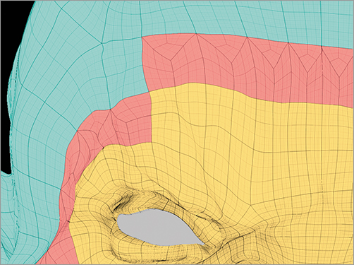
Figure 3-13: The process to locally subdivide a mesh for greater details concentrated in key areas

This area can now handle much higher levels of detail than other, less important areas of the character. When you locally subdivide the original mesh, the transition area and the high-detail area are separately polygrouped to help you work with them.
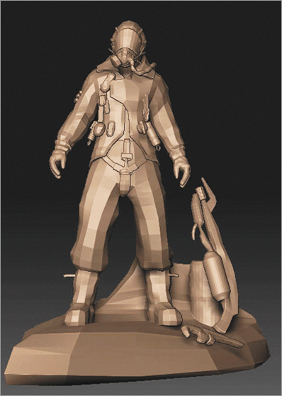
See the book's comanion DVD for a selection of tips and tricks by Fabian Loing, where he discusses the masking technique used in this image. Figure 3-14 is an example of his work.
Figure 3-14: This solider was created by Fabian Loing using some unique masking techniques.