Importing and Preparing a Mesh for Sculpting
To begin, we’ll import the base geometry into ZBrush as a tool. Previously we were selecting ZBrush primitives from the Tool menu. These meshes come preloaded. For the generic head, we need to import it into the program. Remember a model is an OBJ file, which is just a polygon mesh created in a polygon modeling package—it does not carry multiple subdivision levels, layers, and other information. ZTools, on the other hand, are ZBrush models that save polygons, multiple-subdivision levels, sculpted detail, subtools, color and texture information, as well as alphas.
To load the model into ZBrush, choose Tool Load Tool. This will open a file browser dialog box. Browse to the Chapter 3 folder on the book’s DVD and select genericHead.ztl. This will load the head ZTool file into ZBrush. There will be a new icon in the Tool palette representing your imported model under User 3D meshes and 2.5D brushes. By default, this new tool is already selected, so you can now draw it on the canvas by left-clicking and dragging into the document window.
Enter Edit mode, and you are now ready to sculpt on the model.
Before you can sculpt on the tool, it must be immediately placed in Edit mode. If you were to stroke on the canvas again, it would only draw more instances of the mesh on the canvas. As soon as the tool is drawn, enter Edit mode by pressing the T key on your keyboard or by clicking the Edit button at the top of the screen.
Using Polygroups to Organize Your Mesh
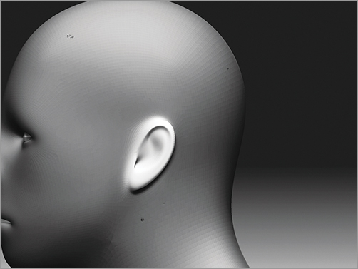
When sculpting a character, it is beneficial to have the model organized into easy-to-select parts to facilitate working on the ears or mouth separately. I want to make sure that I can isolate the ears from the head and manipulate the various parts of the ear without affecting the back of the head. The same is true for the lips. Notice that if you try to move the upper lip with the Move brush, often the lower lip will be moved too since it is in close proximity and lies under the falloff of the Move brush. Masking offers similar problems when you’re trying to paint a mask on just one lip and not both.
Polygroups allow you to quickly and easily isolate parts of the model for sculpting. Polygroups in ZBrush are simply selections of polygons that are tagged as being part of a group. They are similar to selection sets in Maya. Polygroups are assigned a separate color. In Figure 3-15 this stegosaurus has its parts polygrouped into different selections. The polygroups are visible when in Poly Frame mode. Enable this mode by pressing Shift+F or selecting the PolyF button on the Transform panel. The PolyF button is also located on the right sidebar of the document window.
Figure 3-15: Model in Frame mode

Polygroups can help you organize parts of your model into easy-to-access groups. Having polygroups for the character’s ears makes it easy to quickly show or hide the ear geometry to mask this geo independently of the head. Any polygroup can be isolated by Ctrl+Shift-clicking the group. This hides all other polygroups. You can invert this selection to show the hidden groups and hide the currently active one by Ctrl+Shift-clicking and dragging a marquee anywhere off the model on the document background. To reveal all groups again, Ctrl+Shift-click anywhere off the model on the document background.
You create polygroups by choosing Tool Polygroups. In the resulting dialog box you will find several options: Auto Groups, Auto Groups With UV, V Groups, Group Visible, From polypaint, From Masking, and two sliders to control tolerance for the polypaint and masking group options. Auto Groups will automatically create polygroups from separate objects in an imported OBJ file—for example, if you imported an OBJ that was a sphere and a box (Figure 3-16) ZBrush loads them as a single tool. You cannot manipulate them independently from each other. Auto Groups will automatically polygroup the two objects since the OBJ file recognizes them as separate objects even though they import as one tool (Figure 3-17). Auto Groups with UV will generate groups based on the UVs and topology of the object.
Figure 3-16: Sphere and box OBJ file
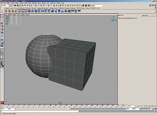
Figure 3-17: Polygrouped sphere and box

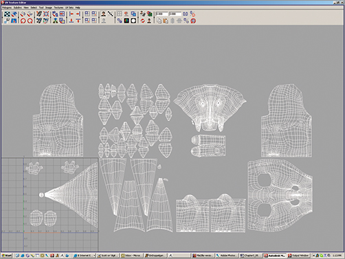
UV Groups will create polygroups from faces arranged in the UV Texture space outside 0 to 1. Notice in Figure 3-18 that the UVs of this character are shifted outside 0 to 1. UV Groups will create new polygroups for any faces outside 0 to 1.
Figure 3-18: This stegosaurus has UVs in multiple regions outside 0 to 1.
Group Visible will polygroup the faces visible in the document window. So if you hide part of the model and then apply Group Visible, those visible faces are tagged as a new polygroup. This is the option we will use to group the ears into separate parts. It is important to note that this does not separate these faces from the mesh or change the geometry at all; it is simply a tool for quickly showing and hiding saved selections.
From polypaint and From Masking will polygroup based on a selection you paint. If you use the Polypaint option each area with a different color painted on will be a separate polygroup. The tolerance for this is controlled with the Ptolerance slider. From Masking will perform the same function but the polygroup will be generated based off areas of the model that have been masked.
It is possible to use the Subtool menu to break apart polygroups into separate subtools. To do this, click Tool Subtool Group Split. This command will separate the grouped parts into different subtools. For more on subtools, see Chapter 5, “Texture Painting.”
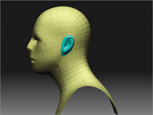
Polygroups have several functions in ZBrush. The one we will examine here is for organizing a complex mesh into easy-to-isolate parts. Notice that if I use the Move tool on the ear I pull not only the ear faces but the faces on the head behind the ear (Figure 3-19). Masking into a tight area like this can be tricky, not to mention time-consuming, if you have to repeatedly mask the ears each time you want to work around them.
Figure 3-19: When using the Move brush on an unmasked ear, you change the ear as well as the faces of the head.

Figure 3-20: The ear faces isolated

You can select two different selection brushes from the Brush menu. These brushes include Select Lasso and Select Marquee. Select Marquee will draw a rectangular selection when you press Ctrl+Shift. Select Lasso allows you to draw an irregular selection area. You can further control the type of stroke for these selection brushes under the Stroke menu while holding Ctrl+Shift. I prefer to maintain the default Select Lasso and Select Marquee assigned to hotkeys.
To polygroup the ear, follow these steps:
1. From the Brush menu select the SelectLasso brush. Begin by hiding the faces using Ctrl+Shift-drag to create a hide marquee. Around the head faces, hide until just the ears are visible. Since this head is symmetrical, you can enable X Symmetry and any faces hidden on one side will be hidden on the other.
2. Once the ears are visible, choose Tool ![]() found under the Transform menu. This will cause any face from which you select one vertex to be hidden. Point Select is in the Transform menu.
found under the Transform menu. This will cause any face from which you select one vertex to be hidden. Point Select is in the Transform menu.
3. The ear is now polygrouped. To see this, Ctrl+Shift-drag in the document window to Reveal All again. Now press Shift+F to enter Frame mode and you can see the different-colored faces for the two polygroups (Figure 3-21).
Figure 3-21: Polygrouped ear faces
It will be useful to have the ring of faces around the ear separated from the ear and head for more flexibility when working on this area. To accomplish this, hide the faces of the head so that only the ear is visible.
4. Hide the ring of faces around the ear. Once the faces are hidden, you can invert what is visible on screen by Ctrl+Shift-dragging a marquee in the document window. This will show the previously hidden parts. Since the head is grouped separately from the outer ear ring, you can hide the head by Ctrl+Shift-clicking the head mesh. Now only the outer ear ring is visible. Assign this a new polygroup by choosing Tool Polygroups Group Visible. Figure 3-22 shows the ear and its individual polygroups.
Figure 3-22: Outer ring polygrouped
Now you can easily mask the ear area by hiding the head using Ctrl+Shift-click. Only the head is visible; the ear is now hidden. Ctrl-click-drag a masking marquee to mask these faces (Figure 3-23). Invert the mask by Ctrl-clicking the background to keep the head masked and the ear unmasked.
Figure 3-23: Masking with polygroups

By masking the ear, you can sculpt against the back of the ear, or by masking the head, you can easily modify the ear and move it without disturbing the faces of the head (Figure 3-24). This makes the process of sculpting the ears independently of the head much easier, especially since you don’t have to constantly re-create a complex mask. Any time you need to mask the head, ear or outer ring, simply hide the rest of the mesh and mask the visible parts.
Figure 3-24: Using masking to help manipulate ear shapes
Using Polygroups to Move the Mouth
The same problems with sculpting the ears also manifest when you’re trying to move the lips independently of one another. When trying to mask or move the upper lip, you will often find the lower lip is moved as well due to their proximity to each other. The brushes will simply affect anything underneath their falloff rings that isn’t masked. The solution to this is to polygroup the lower lip separately from the rest of the head. This makes it very simple to grab one part of the mouth and quickly manipulate it while sculpting.
To polygroup the mouth, we will use steps similar to those we used with the ear, but we first need to mask the lips separately from each other. This can be difficult since the lips are so close; masking one lip invariably seems to create a mask on part of the other. We will need to spread the lips open.
1. Store a morph target of your model by selecting Tool Morph Target and clicking the StoreMT button. This creates a copy of the mesh shape in memory that you can easily return to. You are storing this morph target because you will now stretch the mouth open to facilitate masking the lips. By returning to the stored shape, you can correct any changes made to the mouth while keeping the mask.
2. Select the Smooth brush and smooth the mouth area. This will have the effect of spreading the mouth faces open. You can also get good results using the Inflate brush set to ZSub, as this will push faces apart (Figure 3-25).
Figure 3-25: Opening the mouth with the Smooth brush
This process is somewhat involved, so you would not want to repeat it each time you want to open the mouth. Although the mesh is masked, we can easily create a polygroup; therefore, hiding one half of the mouth is easier.
3. With the lower lip still masked, select Tool Visibility and click the HidePt button ![]() .HidePt will hide any unmasked faces. With the lower lip visible, you can now polygroup it separately from the rest of the head (Figure 3-26).
.HidePt will hide any unmasked faces. With the lower lip visible, you can now polygroup it separately from the rest of the head (Figure 3-26).
Figure 3-26: Polygrouping the lower lip

ZBrush 4 introduced a new brush mask called Topological Masking to help alleviate the issue of moving clips and other objects that may be close together, such as toes. Access this setting by choosing Brush Auto Masking Topological Masking (Figure 3-27). The Range slider will control how far from the center of the brush the effect will carry. The brush will only affect those points topologically close to the brush center, not physically close. This means you can move the upper lip independently of the lower because they are only physically close while topologically the points are far apart. Topological Masking is a useful tool and I recommend using it whenever possible. I still polygroup the lower lip as we showed earlier since I find sometimes it is faster to hide the mask and manipulate the jaw rather than enable Topological Masking and adjust the Range slider. Each approach has its strengths and you will be well served to explore both. The Topological Masking setting is invaluable when working on the toes, for example.
Figure 3-27: The Topological Masking settings under the Brush menu

Setting Up GoZ and Subtool Master
In this section we will be using two ZBrush plug-ins, GoZ and Subtool Master. Subtool Master allows you to perform various functions on multiple subtools. We will use it to mirror parts across the X axis. GoZ allows you to move your work seamlessly between ZBrush and another 3D application. We will use it to add geometry to our creature head.
The Subtool Master plug-in is available for free download from www.pixologic.com. The GoZ plug-in is preinstalled with ZBrush but you have to set it up (see the next section, “Installing GoZ”). Make sure both tools are ready for use before you proceed.
You install Subtool Master by extracting the contents of the zip file to the ZBrush4/ZStartup/ZPlugs folder. GoZ requires a different setup.
Installing GoZ
GoZ comes preinstalled with ZBrush. All you have to do to enable it is click the GoZ button and ZBrush will search for all the applications it is capable of connecting with. When you encounter an application that ZBrush cannot find, it gives you the option to browse to that application’s location or select Not Installed. So, for instance, if you do not have 3ds Max installed on your machine, then you click Not Installed.
The installer will copy scripts into a common folder for the 3D application to use. This will require that you use administrator privileges on your machine during the installation. Once it’s installed, you can take advantage of GoZ’s functionality. If you set the GoZ application to Maya, you will now have a shelf in Maya with a GoZ button. In some cases this particular functionality does not work and you have to add the shelf manually. The following steps show you how to enable the GoZ shelf in Maya:
1. To set up the shelf in Maya, open the Script Editor window in Maya (Figure 3-28).
Figure 3-28: Maya Script Editor window

2. Click File Source script and browse to C:UserspublicPixologicGoZAppsMaya. Here you will find the scripts that allow you to transfer work from Maya back to ZBrush.
3. Select the file called GoZScript.mel and run the script to create a GoZ shelf in Maya (Figure 3-29).
Figure 3-29: The GoZ shelf in Maya

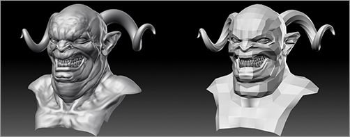
Sculpting a Character Bust
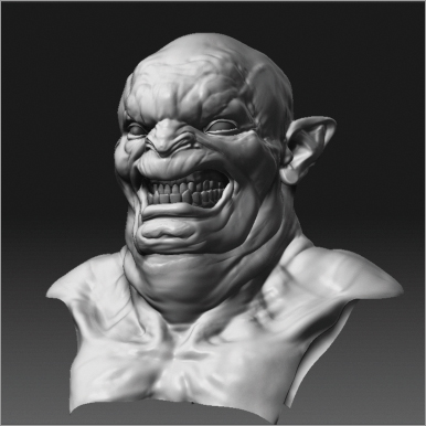
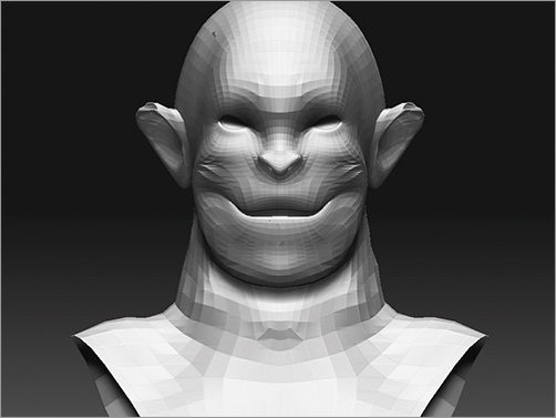
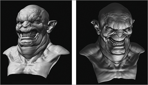
In this section, you’ll sculpt a character from the generic human head bust (Figure 3-30). This ZTool is prepared with mouth and ear polygroups to facilitate a quick sculpting workflow when dealing with these areas. You’ll also add new parts to the head directly using the Insert Mesh function. In the course of this exercise, you’ll make use of the Gravity Brush modifier as well as Transpose. You’ll also use the Subtool Master plug-in later in this exercise. Be sure to download and install this free tool from www.pixologic.com before you begin.
Figure 3-30: This character bust was sculpted from the generic human head mesh.
1. Initially you know that you want this character to be leaning his head back and grinning. The orientation of the head you want is different than that of the generic head mesh. To accomplish this change, use Transpose to shift the orientation of the head on the shoulders. To do this, snap to a side view and mask the shoulders with a lasso. Switch to Transpose Move by pressing the W key and shift the head back slightly (Figure 3-31). Subdivide the mesh by pressing Ctrl+D, and using the Standard brush, build up the anatomy of the neck—at this stage just suggesting the form and direction of the sternomastoid and clavicle.
Figure 3-31: The head shifted back with Transpose Move

2. Now let’s take advantage of the ear polygroups to change the ear shape. Ctrl+Shift-click the ear to hide the head. Using the Move brush, adjust the ear shape into a more monstrous form (Figure 3-32).
Figure 3-32: Isolating the ear and changing its shape
3. Using the Move brush, stretch the mouth back, starting to suggest a grin. At this stage, you can widen the neck and shoulders to give the character a muscular look (Figure 3-33).
Figure 3-33: Creating the grin and adjusting the shape of the shoulders
4. Taking advantage of the polygrouped mouth, let’s open the mouth by masking and moving the shapes (Figure 3-34). At this point let’s also add teeth to the model. (The teeth in this example were modeled by Jim McPherson.) Import them into the Tool palette, and then append them to the model as a subtool. Using the Transpose Move and Scale options, place the teeth in the head. Notice that the teeth here are upside down—I liked the ferocity that this underbite suggested, so I left them flipped (Figure 3-35). At this stage also add polymesh spheres as eyeballs.
Figure 3-34: Opening the mouth using polygroups

Figure 3-35: Teeth imported and placed

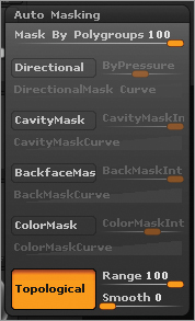
You can sculpt the teeth and gums independently of each other by using one of the Move brush variants new to ZBrush 4. The Move Parts brush will only affect the first part you click on when working with a single subtool composed of separate pieces, as is the case with the teeth. The Move Parts brush allows you to shift the teeth around and create irregularities quickly (Figure 3-36). To sculpt on the teeth without affecting them all at once, use polygroup masking. You’ll find Mask By Polygroup under the Brush Auto Masking menu. Set the slider to 100 for any brush, and the brush effect will be applied only to the first polygroup you click. This is useful, for example, when you’re trying to sculpt striations in the tooth enamel without wanting to affect the gum tissue. For this technique to work, the teeth and gums must have separate polygroups (Figure 3-37). You can accomplish this by clicking Tool Polygroups Auto Groups.
Figure 3-36: Quickly create irregularities with the Move Parts brush.
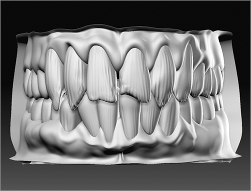
Figure 3-37: Polygroup masking helps you sculpt each tooth and the gums separately.
5. To sculpt the forms of the ear, add another subdivision level and mask out inside the helix of the ear. Invert the mask, and using the Standard brush set to ZSub, carve away the negative space and start to introduce the ear forms (Figure 3-38). Remember to address the parts of the ear, as discussed in Chapter 2, “Sculpting in ZBrush.”
6. Using the Standard brush and alternating between ZAdd and ZSub, carve in the flow of major folds of flesh around the mouth and in the forehead. Take care to make the skin seem compressed at the cheeks by making deep recesses and high puckering rolls to help create the impression that the big mouth is stretching open. We can start to refine the anatomy of the neck, so also use InteractiveLight ![]() to move the light around and check the forms under different lighting conditions. Remember that this utility will only work with the standard materials and not the MatCap materials. For this example, we’re using the BasicMaterial.
to move the light around and check the forms under different lighting conditions. Remember that this utility will only work with the standard materials and not the MatCap materials. For this example, we’re using the BasicMaterial.
7. Since this character is intended to be very fat, you want to add fleshiness and folds to the cheeks and under the chin. Using the Elastic brush set to ZAdd, start massing out the fat underneath the chin. Elastic is similar to Inflate, but it tries to maintain the forms already sculpted and tends to be less destructive of the area you are sculpting over (Figure 3-39).
Figure 3-38: Sculpting the forms of the ear
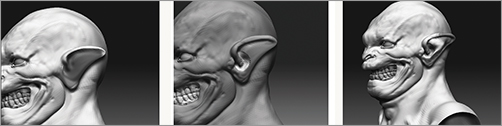
Figure 3-39: Adding fat to the neck with the Elastic brush

8. Let’s make further refinements to the shapes of the face (Figure 3-40). Use the Smooth brush on a low intensity to soften the forms. Create tight puckers between the folds of flesh by using the Inflate brush along the space where two folds meet. This has the effect of creating the look of two folds of skin pressing together.
Figure 3-40: Stroke the Inflate brush between two folds to draw them together in compression.
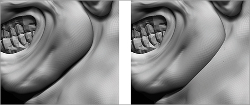
9. Now use the Gravity modifier on the Elastic brush to add a sense of weight to the skin folds. Gravity is acting on our bodies at all times, but it is most apparent in loose-hanging skin like this character’s jowls. Figure 3-41 shows two forms. The form on the left has no sense of gravity, whereas the one on the right has a sense of weight and drag. By adding more body to the bottom of the fold, it appears that the fatty tissue is being pulled down by gravity. This applies to skin folds, finer wrinkles, and even cloth. The Gravity brush tries to automate this process by adding to the surface in the direction of the Gravity arrow (Figure 3-42). You can use Gravity on any brush by simply raising the Gravity slider value under the main Brush menu (Figure 3-43).
Figure 3-41: This figure illustrates gravity and its effect on form. The right image is the sculpted form; the left represents the silhouette of the shape depicted. By adding more visual weight to the bottom of a form, you can create the impression that gravity is acting on it.

Figure 3-42: The Gravity brush modifier
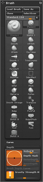
Figure 3-43: Using the Elastic brush with Gravity to add weight to the flesh folds

10. The form is nearly finished and the sculpt is showing a strong sense of character (Figure 3-44). Turn off X Symmetry by pressing the X hotkey and start to “break” symmetry. Breaking symmetry means adding asymmetrical elements to different sides of the head to combat the perfect 3D look.
Figure 3-44: The final form development
Adding Geometry Using Mesh Insert
At this point let’s add more geometry to the head. You’ll add a pair of curved horns to the head. There are two approaches you can take to add geometry. You can insert new meshes and blend them together. Alternatively, you can export the model to an external application and extrude new faces there using the GoZ plug-in. You can then bring this new model back into ZBrush, retaining all your previous sculpting levels.
The strategy we’ll use in this section involves combining subtools using a function called Insert Mesh. This approach allows you to insert new geometry to an existing ZTool and blend it off, just like adding clay. If the model needs to go into an animation pipeline, the resulting model can be retopologized in ZBrush to create a new ZTool with all the detail but as a single mesh.
This exercise will make use of Subtool Master. Make sure you install this plug-in before you begin.
1. For the horn, you’ll use a spiral primitive. You can use any imported mesh, but the spiral is close to the shape we want, so it is faster to create the horn from a ZBrush primitive. From the main Tool menu, select the Spiral3D tool; draw the spiral on the canvas and enter Edit mode by pressing the T key.
2. Under Tool Initialize, change the following settings to alter the shape of the horn to what you need for this character:
Coverage: 619
SDisp: 3.10
SDivide: 9
3. In order for you to merge this horn ZTool into the creature ZTool, it must have the same number of subdivisions. This is so ZBrush can divide and lower the meshes together and let you retain your subdivision levels after inserting new geometry. If the two tools had different numbers of levels, ZBrush could not step them back down together had you lowered subdivision levels. The creature head is currently five subdivision levels. With the Spiral3D tool active, click Make PolyMesh3D under the Tool menu ![]() to create a new horn mesh.
to create a new horn mesh.
4. Return to the creature head by selecting it from the Tool menu. At this stage, you want to append the polymesh horn into the creature tool as a subtool, and then scale and place it where you want it. Click Tool Subtool Append ![]() and select the polymesh horn from the Tool palette popup. Be sure to select the PM3D version and not the original ZBrush primitive. Doing so will add the horn as a subtool.
and select the polymesh horn from the Tool palette popup. Be sure to select the PM3D version and not the original ZBrush primitive. Doing so will add the horn as a subtool.
5. Activate the subtool by selecting it from the Subtool list (Figure 3-45). Use the Transpose, Move, Rotate, and Scale buttons at the top of the screen to move the horn into place. Be sure to sink it slightly into the surface of the head.
Figure 3-45: The horn is now added as a subtool.

6. Now let’s mirror the horn across the midline so there will be two horns, one on each side of the character head. To do this, you will use the Mirror function of the Subtool Master plug-in. Open Subtool Master from the ZPlugin menu, and with the horn subtool selected, click Mirror. Be sure Merge Into One SubTool is checked (Figure 3-46). This step will mirror the horns across and merge them into a single subtool.
Figure 3-46: Subtool Master’s Mirror function

7. The next step is to combine the horns into the creature head using the Insert Mesh function. Be sure the head and the horns have the same number of subdivision levels. If you don’t do this, you will lose subdivision levels from your ZTool. Select the horn subtool and click the Clone button to create a new ZTool of the mirrored horns (Figure 3-47). Click Tool Geometry Insert Mesh and select the cloned horns from the Tool palette menu that pops up here. As long as both tools have the same number of subdivision levels, the horns will now be inserted into the head subtool, retaining all subdivision levels (Figure 3-48).
Figure 3-47: Cloning the horn subtool
Figure 3-48: Once the horn is inserted, it becomes part of the head geometry and you regain all your subdivision levels.
A benefit of using Insert Mesh to combine subtools is that you can now seamlessly blend the two subtools together. Once the two meshes are blended, you can remesh across them and make a new unified ZTool. See Chapter 7 for more information on retopology. Now using the Clay brush, you’ll blend the horns into the character head.
1. Select the Clay brush from the Brush menu. Be sure the brush is set to ZAdd and the BrushMod value is set to 10 or more.
2. Stroke along the edge where the horn intersects the head and the seam will blend away (Figure 3-49). While these two objects are not merged geometrically, simply using the ZBrush remeshing tools allows you to make a single ZTool from multiple inserted meshes.
Figure 3-49: The Clay brush can blend away seams between inserted meshes.
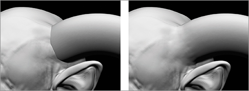
Using the Smooth brush across a Mesh Insert seam can cause the two parts to separate. Instead of using the Smooth brush, use the Claytubes brush with no alpha. This will have a smoothing effect on the surface while maintaining the blend. Once the seam is smooth, you can switch back to the Smooth brush.
That completes the first character you’ll design in this chapter. We have looked at polygrouping, creating a sense of gravity in our sculpture, introducing interactive light, and using Mesh Insert. If you would like to see the entire process involved in creating this character, check the accompanying DVD. In the next section, you’ll create the character from the cover of this book. You’ll use many similar techniques, but you’ll add new geometry in a totally different way.