ZBrush is capable of creating 16-bit and 32-bit maps in single-channel grayscale or three-channel RGB. In this section, we’ll discuss how to create two kinds of displacement maps, 16-bit and 32-bit. Regardless of the type of map you generate, it is important to be aware of the shape of the base mesh from which you generate compared to the mesh on which you will render it.
Accessing Your Original Mesh Shape
ZBrush is a multiresolution editing tool, meaning that changes you make at the higher subdivision levels will telegraph back down to the lowest subdivision level, somewhat changing the shape of the original mesh. In some cases, you may want to access your original mesh shape again; for example, you may want to generate a displacement map against the shape built in Maya, as opposed to the somewhat different level 1 shape that will result after sculpting in ZBrush. Here are some hints for doing this:
- To ensure that you can return to the original Maya shape in ZBrush after sculpting, store a morph target before you begin sculpting by clicking Tool Morph Target StoreMT before you start modifying your model. After sculpting, you can use Tool Morph Target StoreMT to switch back to the original shape.
- An alternative way of doing this, which does not require storing a morph target, is simply to reload the Maya model after sculpting as the level 1 mesh of your sculpted model. This approach will work as long as vertex ordering has not changed (which should be the case as long as you have not added or removed points or edges). The morph target method is generally preferred because some programs can, on occasion, alter the order in which they write model vertices on export, even when the model has not changed at all.
- It is also important to note that using tools like the Pinch Brush will make changes to the mesh that will not necessarily translate well into the maps created when setting a DPSubPix value as opposed to those generated using Adaptive mode (these settings will be discussed in detail later). This explains why, in many cases when using these tools on your mesh, you’ll find it beneficial to use the slightly shape-modified level 1 mesh for your base in Maya as opposed to the original morph target.
- In any case, always apply your displacement map to the geometry you generated it from in ZBrush. If you use the original morph target, be sure to export this mesh to Maya for displacement.
If you find that areas that have been pinched together are creating undesirable effects in the render, try using the Reproject Higher Subdiv button under Tool Geometry. Reproject Higher Subdiv will allow you to relax the underlying edges while maintaining the sharp edges. This tool is discussed in depth in Chapter 2, “Sculpting in ZBrush.”
If your base mesh is already rigged and cannot be changed in Maya, export the ZBrush level 1 mesh as an OBJ import into your Maya scene, and add it as a parallel blend shape to reshape the original mesh to the level 1 form exported from ZBrush.
Making 16-Bit Maps
You created a 16-bit map earlier when you created the displacement map for the GoZ export exercise. Here we will look at the 16-bit map settings in more detail. Sixteen-bit maps carry less information than 32 bit. They can give great results when used correctly, but it will come down to a question of artist preference as well as pipeline requirements when deciding whether to use 16-bit or 32-bit maps.
Generating a 16-bit map in ZBrush is simple. To do so, follow these steps:
1. Step down to your lowest subdivision level in ZBrush. Make sure the mesh has UVs that do not overlap. You may choose to generate UVs directly inside ZBrush using AUV or PUV tiles at this time.
2. Select Tool UV Map and select the 2048 button (this value can be higher or lower, but multiples of 2 are recommended, as in 1024, 2048, or 4096). If you do not have UVs already on the mesh, click the AUV or PUV button to generate automatic UV coordinates.
3. Under Tool Displacement, set your DPSubPix to 1 and click Create And Export Map (Figure 9-28).
Figure 9-28: The Displacement Map options

4. The map will generate and export to the selected location on the disk. To do this manually, click the CreateDispmap button. The map will generate and appear in the Alpha palette window under Tool Displacement when it is complete (Figure 9-29).
Figure 9-29: Once the map finishes generating, you will need to press CloneDisp to make it appear in the Alpha palette.

Keep in mind that at this stage the map cannot be exported; you must click CloneDisp to clone a copy of the displacement map and make it appear in the Alpha palette. Once you complete this step, you can manually export the map from ZBrush. While the map is in the displacement swatch, it can be saved with the ZTool and accessed later.
Remember that if you do not intend to save the displacement map with the ZTool but simply want to export and render, instead of clicking the Create DispMap button select the Flip V button and click Create And Export Map. This will generate the displacement map, flip it in the V direction, and save it to disk. This process will bypass the stage of loading the map into the Alpha palette.
If you click the Create And Export Map button, you will get a 16-bit map if you do not have the 32Bit button enabled.
You may notice that ZBrush will attempt to display a displacement map on the surface of the model when it is loaded in the displacement slot under Tool Displacement. This can be helpful when checking maps or troubleshooting render issues if you want to make sure there are no visible artifacts in a displacement map you have generated inside ZBrush. You can turn this off by clicking the Disp On button. The Mode button will determine if the map is displayed as a bump map or if it will displace the surface of the model when you click the Apply DispMap button. This can be useful for reconstructing ZTools from a base mesh and a displacement map if the original ZTool has been lost.
Making 32-Bit Floating-Point Maps
There’s an added benefit to creating a 32-bit map; it carries real-world scale baked into the map. This allows you to create more accurate and detailed renders in software that can handle such large maps.
When you create 32-bit maps, you use the same menus that you do when creating 16-bit maps, but you have access to a few more options and a different button to generate and export the map. Had we wanted to create a 32-bit map in the previous exercise, we would have enabled the 32Bit button under Tool Displacement Map.
You can export 32-bit maps from ZBrush but you cannot reimport them. Further, you cannot display a 32-bit map inside ZBrush. This is because the maps carry so much detail and information that ZBrush cannot display them in real time. Once you generate a 32-bit map, it is immediately exported to the hard disk for use in an external renderer.
The 32-bit floating-point maps generated in ZBrush should not be edited in an external editor—doing so may alter the map in undesired ways.
Follow these steps to create a 32-bit floating-point displacement map:
1. With your ZTool at the lowest subdivision level, choose Tool Displacement. Select any alpha in the preview swatch so that all the options in the window become active. In the Displacement settings enable the following buttons: Flip V, 3 Channels, and 32Bit. Also set the Mid slider to 0.
2. Click the Create And Export Map button. ZBrush will prompt you for a file save location and filename.
The importance of having real-world scale baked into a 32-bit map is to simplify the rendering process. Sixteen-bit maps record only that one point is higher than another point; 32-bit maps record the relative height of the highest point and depth of the lowest point in relation to the overall scale of the object. This means that your settings in Maya will remain consistent for all 32-bit displacement maps you render. At the same time, 16-bit maps require some rescaling of values to achieve proper renders.
Multiple Maps per UV Region
In instances where you have multiple UV regions for a character, you will want to generate maps for each part. To do this, simply generate polygroups based on UV region by choosing Tool Polygroups Auto Groups With UV. This will create polygroups for each UV region. Ctrl+Shift-click to hide other regions and generate and export a map for each part at a time.
Displacement Menu Options
We have already used the displacement menu to create a 16-bit map. Let’s now take a closer look at the options in this menu and what they mean (Table 9-1). Figure 9-30 shows the menu with various callouts to the function of each button. Please see the accompanying DVD for a video concerning this menu and some unique functions available in it.
Figure 9-30: The Tool Displacement Map menu and its functions

Table 9-1: Displacement menu options
| Option | Description |
| Preview Swatch | Shows a preview icon of the currently selected displacement map. |
| Disp On | Enables the display of the selected displacement map. |
| Clone Disp | Copies the current map to the main Alpha menu to facilitate export. |
| Intensity | Sets the display intensity of the displacement map inside ZBrush. |
| Mode | Sets the display mode of the currently selected map. If deselected, displays as bump map; if selected, displaces the mesh with the current map. |
| Apply DispMap | Applies the displacement map to the mesh. |
| Create DispMap | Generates a displacement map based on the current settings. |
| Adaptive | Adaptive mode will subdivide the mesh in more detailed areas while generating the map. This works more like a raycasting. |
| DPSubPix | This mode will subdivide the mesh while generating the maps. |
| SmoothUV | Smooths the UV coordinates when generating the mesh. |
| Mid | Sets the midpoint value of the mesh—leave this at .5. |
| Flip V | Flips the map vertically. |
| 3 Channels | Creates an RGB map. |
| 32 Bit | Sets the bit depth from 16 to 32 bit; when on, this will enable the scale slider. |
| Scale | This slider sets the object scale when generating a 32-bit map; leave this at 1. |
| Create AndExport Map | Create and export the 32-bit map; must be used when working with 32-bit maps as they cannot be displayed in ZBrush. |
The difference between DPSubPix mode and Adaptive mode is in how the displacement map is generated. DPSubPix mode is a global subdivision value. With DPSubPix set to 2, for instance, when ZBrush generates the map it subdivides the entire mesh two more times in memory, thus allowing you to create a crisper, higher-quality map. Adaptive, on the other hand, is a feature-based displacement mode. This means that as the map generates, ZBrush will subdivide only those areas of high detail. For this reason, adaptive mode is sometimes faster than DPSubPix. Both map types have their benefits.
Processing Displacement Maps for Use in mental ray
It is important to remember that with the 32-bit map export, there is no reason to open your map in external image-editing software and resave it. In many cases this will destroy the floating-point data and render the map useless.
Maya provides a nice utility called imf_info.exe in the Maya/bin directory. You can use this program at the command line to read detailed information about your displacement map.
imf_disp.exe is another utility that will display maps and offer information on them. This utility features a graphic interface.
Your displacement maps will perform far better, faster, and with more stability in mental ray if you convert them to the mental ray native file format, MAP. The difference is especially apparent with higher-resolution maps. Maya will process the render at a noticeable speed increase in many cases, and crashes are less common when working with larger map resolutions. Using the MAP file format will also increase your speed at render time because MAP files use mental ray’s memory-caching features. Taking care with how mental ray handles memory will speed up renders and make for far better performance. This process is automated in newer versions of Maya but this section will show you how to manually convert any file to the MAP format.
mental ray comes with another command-line utility called imf_copy, which will allow you to convert TIFF files to the MAP format. To run this utility, open a command window in the folder where your TIFF files are located. Use the following command line to convert to MAP format:
imf_copy -p originalfile.tif newfilename.map
To open the command window on a Windows machine, choose Start Run and type command.
Perform this conversion on all displacement maps you plan to use. The maps will cache in memory and render faster and with fewer crashes. Included on the DVD is a Windows batch file to automate this conversion process. Simply drag and drop your TIFF files onto the convertfile.bat icon, and they will convert and save in the original location.
Newer versions of Maya have a utility built in to do this conversion for you as files are used. The following steps will show you how to enable this function.
1. Open Window Settings And Preferences Preferences.
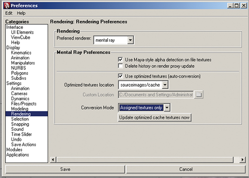
2. Select the Rendering menu and check the Use Optimized Textures box.
3. Click the Use Optimized Cache Textures Now button to convert all the assigned texture maps to MAP format in cache to help the renders run faster and more efficiently (Figure 9-31).
Figure 9-31: Setting the rendering preferences in Maya 2009 to convert textures to MAO format automatically