ZSketch is a brush-based mesh generation tool that allows artists to build meshes by applying tubes of digital clay to a ZSphere armature or other base. Figure 10-1 shows a ZSketch model of a vehicle that comes with ZBrush. The forms are created by a number of individual strokes, which are each composed of a series of spheres. I liken it to sculpting by laying down ropes of clay. The ZSketch tools are fast and gestural, and lend themselves to quickly building up geometry for sculpting.
Figure 10-1: ZSketch model of a scooter with driver

In this section we will use ZSketch over a ZSphere armature to quickly build a gesture sculpture of a figure. Remember that gesture is the overall motion or action of the figure. A gesture sculpture is not as concerned with form or proportion as much as capturing the life or action in a pose (Figure 10-2). We are using ZSketch in the same way a sculptor uses a lump of water clay to create a quick gesture sketch of a figure, as shown in Figure 10-3. These figures are intended to only capture the gesture or action of the pose and are fantastic exercises in learning to see what makes a figure exciting to look at. By creating these 5-minute sketches in clay, sculptors hope to teach themselves to quickly spot the nuances in the figure that make it seem alive and full of character.
Figure 10-2: The final gesture figure we will sculpt in this section. The focus is on capturing the life or action of the figure.
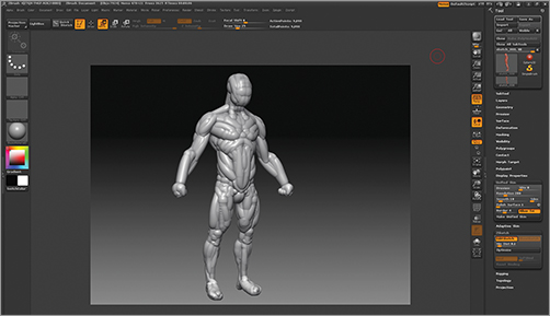
Figure 10-3: These thumb maquettes are 5-minute clay sculptures from life. They are intended to help you see the gesture inherent in the figure.

In this section we will create a quick gestural sketch of a figure using the ZSketch tools over a ZSphere armature. This is a great exercise on its own or a fantastic way to generate a base mesh to sculpt over. Your gesture sculpture in this section will benefit from some experience with sculpting the human form and some familiarity with anatomy and the rhythms of the body. The accompanying DVD contains a full video of the following exercise in action.
For more lessons on these topics, see my book ZBrush Digital Sculpting Human Anatomy (Sybex 2010).
Using the same process you learned in Chapter 6, “ZSpheres,” we will now build a ZSphere skeleton to serve as our armature. This will function exactly like the wire armature that clay sculptors use to support their work. We will even bend this skeleton into a pose that carries the correct gesture of the figure.
1. Begin by loading ZBrush. You may want to initialize the program if you have other projects open. Initialize ZBrush by choosing Preferences Initialize ZBrush.
2. From the Tool menu, select a ZSphere and draw it on the canvas. Be sure to enter Edit mode and turn on X Symmetry.
3. Create a ZSphere chain for the torso, as shown in Figure 10-4.
Figure 10-4: Create a ZSphere chain for the torso.
4. Branch off shoulders and hips from this central chain (Figure 10-5). Further extend these into arms, legs, and a head (Figure 10-6).
Figure 10-5: Adding shoulders and hips to the armature
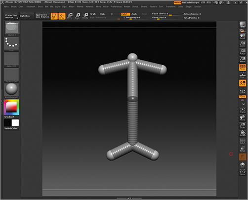
Figure 10-6: Further refine the armature with arms, legs, and a head.

5. The armature is very stiff at this stage. Remember the gesture curves through the figure we discussed in Chapter 1, “Sculpting, from Traditional to Digital.” We want to add some spheres to the legs to help create the same S curve shape in this armature (Figure 10-7). By adding it here in the armature, we make it easier to translate into the finished sketch (Figure 10-8).
Figure 10-7: Add ZSpheres to the legs to create the S curve shown here.
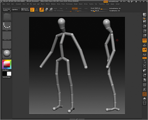
Figure 10-8: Adding the S curve shape in the armature helps to translate it into the finished sketch.

6. Once the armature is complete, open Tool ZSketch and click Edit Sketch. This will place the ZSphere chain into ZSketch mode (Figure 10-9). With Edit Sketch on, you can no longer edit the ZSpheres but you can start to add ZSketch strokes. At this time we will turn our attention to the ZSketch brushes available under the Brush palette (Figure 10-10). These brushes only appear when you’re working with ZSpheres.
Figure 10-9: Exit Sketch enables ZSketching on the armature.

Figure 10-10: The ZSketch brushes

At this stage we have completed our armature and we are now ready to use the ZSketch brushes to build a form on the ZSphere base. The ZSketch brushes will apply ropes of ZSketch spheres to the armature. These can be smoothed, pushed, pulled, and bulged with the ZSketch tools. If you press the A key at any time while sculpting, you can preview the resulting Unified Skin that will be generated by the ZSketch. ZSketch defaults to making a Unified Skin mesh instead of an adaptive skin like ZSpheres. The Unified Skin settings are available under Tool Unified Skin (Figure 10-11). When you have completed the ZSketch, you can create a new sculptable polymesh from the sketch by pressing Tool Unified Skin Make Unified Skin. At any time you can adjust the resolution of your skin by changing the Tool Unified Skin Resolution slider.
Figure 10-11: The Unified Skin menu

The ZSketch brush menu is relatively limited compared to the standard sculpting brushes. Don’t be misled by this—there are many highly useful brushes in this set. Table 10-1, in a moment, lists each brush and its uses. My personal preference is Sketch1 and Smooth1. Experiment with them on your own and see what combinations work best for you.
Sketch1 will add form just on top of the surface in a limited manner. It does not add as aggressively as the other sketch brushes. I like this as it allows me to build shapes gradually whereas the other brushes tend to add too much, too quickly for my taste. Figure 10-12 shows how Sketch1, Sketch2, and Sketch3 add their strokes to different depths on the surface. Sketch1 is the shallowest.
There are many options for Smooth brushes with ZSketch. Each one will treat the ends of the stroke differently. Smooth1 is my smooth brush of choice in most cases, but each Smooth brush will have its place as you work, so be sure to try to work with each one to get a feel for how you prefer to utilize them. In Figure 10-13 you can see the effects of the various Smooth brushes. If you are in doubt about a brush, the icon usually helps clarify the effect it will have. You can also review Table 10-1 for a description of each ZSketch brush.
Figure 10-12: The Sketch1 brush adds form less aggressively than the other brushes.
Figure 10-13: The Smooth brushes in action

Table 10-1: ZSketch brushes
| Brush | Description |
| Armature | Draws strokes off the surface like vines and tentacles. |
| Bulge and Flush | Bulges the strokes and brings them flush to the surface. |
| Bulge | Bulges or inflates the strokes. |
| Float | Moves strokes away from mesh/ZSphere along the stroke direction. Holding Alt will push the stroke back into the mesh/ZSphere. |
| Flush | Aligns the strokes along the document plane. |
| Flush Dynamic | Aligns the strokes along the plane but in the direction of the brush stroke. |
| Flush Res | Aligns strokes along the document plane but resizes them at the same time. |
| Push Pull | Pushes and pulls the stroke based on the brush position. |
| Sketch1 | Draws a ZSketch stroke close to the surface. |
| Sketch2 | Draws a stroke halfway into the surface. |
| Sketch3 | Draws a stroke on the surface. |
| SketchA | Draws a ZSketch stroke close to the surface but with a once orientation. This means the stroke is oriented to the first point that you touch with your brush. This is the opposite of continuous orientation, which reorients the stroke along the surface of the model. |
| SketchB | Draws a stroke halfway in the surface but with a once orientation. |
| SketchC | Draws a stroke on the surface but with a once orientation. |
| Smooth1 | Smooths and blends the end of the stroke to match the size of the underlying mesh/ZSphere; will also blend color. |
| Smooth2 | Smooths and blends color but will not adjust the size of the end of each stroke. |
| Smooth3 | Smooths the stroke with no color blend or size adjustment. |
| Smooth4 | Smooths, blends the color, and adjusts the size of the ends to be smaller than the adjacent mesh/ZSphere. |
We are now ready to use the ZSketch tools to start building our gesture sketch. Make sure that your armature is in Edit mode and you have Tool ZSketch Edit Sketch active.
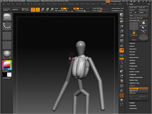
1. Since we are just starting the figure and we need to build the major masses quickly, select Sketch2. Using Sketch2, build the ribcage, as shown in Figure 10-14. As you draw strokes, make it a rule of thumb to always smooth each stroke as you go. This will help you build your form gracefully, and it keeps the ZSketch from growing too large and bloated.
Figure 10-14: Build the ribcage of the figure using the Sketch2 brush.
2. Build strokes down the arms and abdomen, then create a block for the pelvis (see Figure 10-15).
Figure 10-15: Building the arms, abdomen, and pelvis with ZSketch strokes

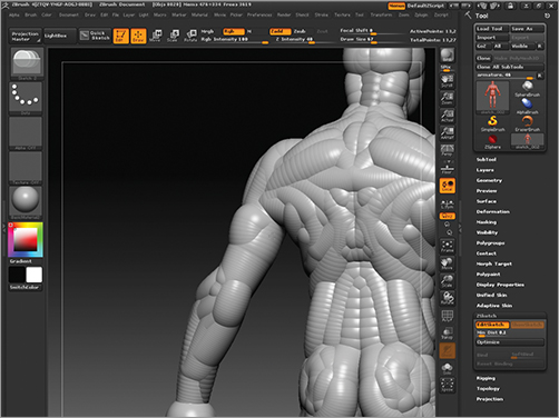
3. Further refine the forms of the legs. In Figure 10-16 you can see the strokes used to build the knees and calves. You can also see the buttocks suggested with brush strokes. We are most concerned with big shapes and broad strokes. Avoid trying to represent individual muscles as much as possible.
Figure 10-16: From the back view, you can see the knees, calves, and buttocks built with strokes.

4. The torso and head are further refined with more strokes. Don’t be afraid to work quickly and smooth your strokes as you go (Figure 10-17). Work from the side view as well. Aim to capture the rhythms in the silhouette of your figure (Figure 10-18).
Figure 10-17: The torso built up with more strokes. Notice that the head and the trapezius muscles are now suggested.

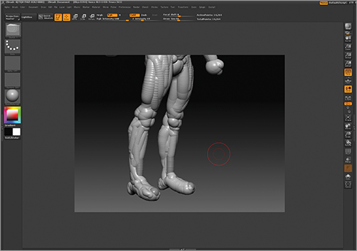
Figure 10-18: The left inside view. The strokes are used to represent the overall outline or silhouette of the leg.

5. After further work on the torso, you can see how the strokes are laid out in a simplified manner to represent the overall form. In Figure 10-19, single strokes represent the abdominal muscles and the oblique muscles of the midsection. I have also added small balls for the fists.
Figure 10-19: Use single strokes as much as possible to represent shapes like the abdominal muscles or the fists.

6. You can isolate strokes by Ctrl+Shift-clicking on them. This will hide all other strokes and allow you to mask just the visible stroke. Here I have masked everything but the back of the arm. I can now use the Bulge brush to suggest the mass of the triceps muscle on the back of the arm (Figure 10-20). Figure 10-21 shows the back of the figure where you can see strokes for the mass of the triceps as well as other major muscle forms of the back. Notice that I don’t try to capture any detail—just general form.
Figure 10-20: Strokes can be isolated and masked independently to help localize your sculpting.

Figure 10-21: The strokes of the back and arm muscles
7. The shape of the legs is further worked by adding the alternating curves of the inside and outside edges of the silhouette (Figure 10-22). From a three-quarter view I smooth and work the strokes with the Bulge brush to help capture the shape I want (Figure 10-23).
Figure 10-22: Working the shape of the legs from the front view

Figure 10-23: The leg shapes worked in three-quarter view
8. Continue to work the figure’s gesture from all views. In Figure 10-24 you can see I have adjusted the slope of the shoulders and the inclination of the head. While I work, I try to draw the strokes in the direction of the muscle flow and the rhythms I want to represent in the figure (Figure 10-24). It may require that I move some strokes around a bit. You can always move strokes by pressing the W key to enter Move mode. Reenter Draw mode by pressing the Q key. Remember you can preview your mesh while you work by pressing the A key (Figure 10-25).
Figure 10-24: The gesture of the torso is adjusted from the side view.
Figure 10-25: Press the A key to preview your unified skin mesh as you work.

9. When your gesture sculpture is complete, you’ll want to save the ZSketch file as a ZTool in case you want to revisit it later. Choose Tool Save As to save the ZSketch. Now, to create a new mesh, click Tool Unified Skin Make Unified Skin. This will create a new unified skin mesh in the Tool menu. Select and sculpt on this tool as you would any other polygon model.
10. As you work, it is possible to move the underlying ZSphere chain armature to alter the pose or proportions of the figure. To do this, click Tool ZSketch Edit Sketch to disable Edit mode then click the Bind button (Figure 10-26). The ZSketch will become transparent.
Figure 10-26: Turn off Edit Sketch and turn on Bind to pose your ZSketch.

11. Switch to Move (press W) and Rotate (press R). Click and pose the ZSphere skeleton as you saw in Chapter 6. The ZSketch strokes will follow (Figure 10-27). You can adjust the range of the bind by adjusting the SoftBind slider under Tool ZSketch (Figure 10-28). Click Edit Sketch again to exit Bind mode and return to ZSketch mode.
Figure 10-27: ZSketches can be posed using the Move and Rotate tools on the ZSphere skeleton.

Figure 10-28: The SoftBind slider controls the falloff assigned for each joint to the ZSketch.

That completes this exercise on using ZSketch for gesture sculpture. You can work loose like this or you can choose to be more specific and careful with your sculpting approach. I find ZSketch works best for me as a sketch tool where I lay in strokes in the direction of the action line I want to establish. I always try to smooth each few strokes as I go. ZSketch is very useful for me on jobs where I need to sculpt vines, tentacles, or other chaotic tendril shapes that would be difficult to do in polygons in a short time frame.
The following exercise illustrates how to use ZSketch to create an ornate tracery design and project it onto a shield.
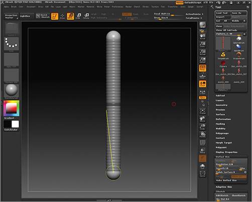
From the accompanying DVD open the shield.ztl file. This is a shield shape with a ZSphere loaded as a subtool (Figure 10-29). We will use the ZSphere as a base to create ornate ZSketch strokes on the surface of the sphere.
Figure 10-29: Open the Shield ZTool.

1. Make sure the ZSphere is selected as the active ZTool. Choose Tool ZSketch and enable Edit Sketch. You can now create ZSketch strokes directly on the surface of the shield (Figure 10-30).
Figure 10-30: With Edit Sketch enabled, you can draw strokes directly on the shield.

2. Use the ZSketch brushes to create an ornate pattern for the shield. Notice that the strokes conform perfectly to the surface as you draw them (Figure 10-31).
Figure 10-31: Drawing strokes directly on the shield using ZSketch

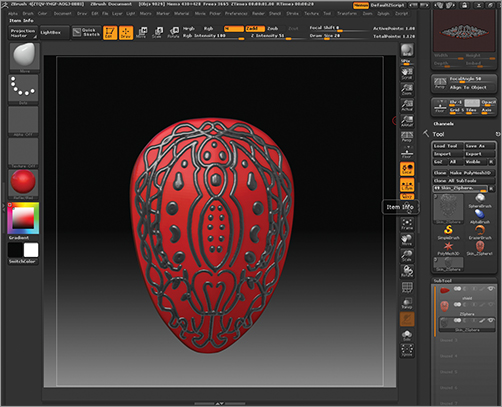
3. When you are done creating your design, create a unified skin mesh by choosing Tool Unified Skin. Click the Preview button to make sure your settings will capture the detail of the sketch. Figure 10-32 shows a sketch that is too fine for the resolution setting. In Figure 10-33, I raised the Resolution slider value to 264, allowing the detail to come across intact.
Figure 10-32: A low resolution setting under the Unified Skin menu will fail to capture the sketch details

Figure 10-33: Raising the resolution slider to 264 captures the detail.

4. Create a mesh by choosing Tool Unified Skin Make Unified Skin. Remember to append the new ZTool as a subtool and hide or delete the original sketch subtool (Figure 10-34).
Figure 10-34: The final shield with ZSketch tracery