
We will now move on to creating hard-surface models in ZBrush. For this exercise we will build a sci-fi ray gun using ZSketch to build our base form. We will then move on to the Clip, Planar, and Trim brushes to create complex machined shapes that have, until recently, been impossible to create in ZBrush. Figure 10-35 shows the final gun we will create in this exercise. It is also possible to combine mechanical and organic shapes to create interesting characters. Figure 10-36 shows a character created by combining organic and industrial forms.
Figure 10-35: The final gun from this exercise

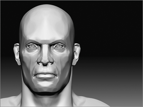
Figure 10-36: This character was created by combining organic and hard-surface sculpting techniques.

When I refer to the hard-surface brushes, I am really talking about a variety of brush tools that have been introduced to ZBrush since version 3.5. While some of them, like the Polish brushes, are not intended solely for mechanical modeling, others are designed purely for creating machined shapes.
Hard-Surface Brushes
Hard-surface brushes fall into four categories (Figure 10-37):
Figure 10-37: The highlighted brushes are used in the creation of hard-surface forms.

- Clip
- Planar
- Polish
- Trim
Together these brushes are generally referred to as the hard-surface brush set. You’ll need a level of understanding of how these brushes behave to fully appreciate the effects you can achieve with them. I highly recommend that you explore using a variety of the brushes on your own to see what works best for you. In the following exercise I will show you my hard-surface technique, which relies heavily on the Clay and Form brush to build general shapes, the Trim brushes to plane the shapes down into angeled surfaces, and the Clip brushes to further carve away more complex forms (Figure 10-38).
Figure 10-38: This image shows a hard-surface methodology. A general shape is created, then carved and shaped using the Clip brushes.

Clip Brushes
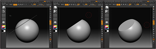
Access the Clip brushes by pressing Ctrl+Shift. When selected, they will replace the default selection Marquee or Lasso brushes. They function by creating a selection, which is flattened into the rest of the model. Figure 10-39 shows a sphere before and after using ClipCurve. Clip brushes have a feathered edge that represents the side that will be clipped.
Figure 10-39: The Clip brush in action
You can move the Clip brush stoke by pressing the spacebar. If you discover you want to clip the opposite side from the feathered edge, simply hold the Alt key and the clip plane will be reversed. One useful trick is to press Ctrl+spacebar to open the menu shown in Figure 10-40. Turning on Polygroup will cause ZBrush to automatically polygroup any faces you clip (Figure 10-41).
Figure 10-40: Pressing Ctrl+spacebar reveals this menu.

Figure 10-41: Faces clipped with Polygroup turned on
You can further refine the clip plane by adding anchor points. Press the Alt key once while drawing a clip line to create a curve point; press Alt twice to create an anchor point for a right angle (Figure 10-42). With these tools you can create complex compound mechanical shapes faster than in any other program. It is literally like sculpting mechanical forms (Figure 10-43). Be sure to see the accompanying DVD for a video on the Clip brushes.
Figure 10-42: Laying in anchor points can further refine the clip plane.

Figure 10-43: This mechanical form study was created entirely using spheres and the Clip brushes.

Planar Brushes
The Planar brushes will flatten the mesh based on the direction of the underlying surface normal and the document plane. The depth at which they will carve away form is dependent on the Depth setting under the Brush menu. The Imbed feature will determine how far a Planar brush will begin its depth into the surface (Figure 10-44).
Figure 10-44: The brush Depth Mask control sets how deep into the surface the Planar brush functions.

Many of the Planar brushes make use of the new backtrack setting under Stroke LazyMouse (Figure 10-45). PlanarLine, for instance, allows you to bevel an edge using the Backtrack Line setting (Figure 10-46).
Figure 10-45: Planar line used to bevel an edge

Figure 10-46: The new Backtrack Stroke settings are used by many of the Planar brushes to create unique tools.

The Trim Brushes
The Trim brushes will trim away at the surface while respecting the surface normals and maintaining an edge along the stroke. Only two Trim brushes will respect the document plane (TrimFront and TrimNormal) whereas all others will evaluate the surface normals along your brush stroke. Figure 10-47 shows the Trim brushes in action.
Figure 10-47: The Trim brushes in action

The Polish Brushes
The Polish brushes will respect all edges. The hard edges will be maintained as the stroke is moved along the surface. The surface is relaxed along the stroke to form a flat surface.
The Polish brushes often help support the other hard-surface brushes. Notice how in Figure 10-48 the Polish brushes help refine the transitions between the Trim brush planes. They help to reduce the sharp edges while retaining the sense of structural form in the sculpture.
Figure 10-48: The Polish brushes in action
Backtrack
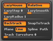
Backtrack is a new subset of LazyMouse that helps you create straight lines or force your stroke to conform to a path. Backtrack is enabled under Stroke LazyMouse (Figure 10-49). When working with Backtrack, you’ll find it best to turn Track Curvature up. This ensures that the stroke will continue to affect the surface even when it is curvy and not flat to the camera. SnapToTrack forces the stroke to conform to the line or curve you draw. You can turn this off for total freedom in your stroke, but often you want to confine your stroke to the path you draw for accuracy.
Figure 10-49: The Stroke LazyMouse menu with Backtrack on
The Backtrack options are as follows:
Plane Plane applies a virtual plane to the surface. Anything intersecting this plane will be sliced by the tool.
Line Line constrains the stroke to a straight line. Hold Shift to conform the line to a 45-degree angle as you draw. I will often use Pinch with Backtrack Line and SnapToTrack enabled to create sharp, straight lines on mechanical forms.
Spine Spine conforms the stroke to a smooth curve between the point where you press the pen down and the endpoint.
Path Path conforms the stroke to a user-defined.
ShadowBox, Group Loops, and Matchmaker
In addition to the hard-surface brushes, we will use several new tools. We will use ShadowBox to create some mechanical parts. ShadowBox is a new mesh generation tool that allows you to draw an object’s profiles to generate it in 3D space (Figure 10-50). We will also use group loops to help create sharp edges (Figure 10-51). Finally, we will look at Matchmaker for taking one shape and conforming it perfectly against another. This is a fantastic tool for creating ornaments, moldings, and other detailed shapes that need to conform against a surface (Figure 10-52). Before we try to implement these techniques on a new model, let’s explore each of these new tools with some brief exercises.
Figure 10-50: ShadowBox allows you to create geometry by drawing.

Figure 10-51: Group loops help you isolate and extrude areas of the mesh, keeping perfectly sharp borders.

Figure 10-52: Matchmaker conforms one shape to another. It’s perfect for housings, molding, and ornate tracery.

Using ShadowBox and Group Loops
In this exercise you will use ShadowBox to create new geometry. ShadowBox lets you create new 3D objects by simply drawing their profiles with the masking tools on a three-sided box that represents front, side, and top views. Please be sure to see the accompanying DVD for a video on this process. Let’s get started:
1. Initialize ZBrush to create a new scene. From the Lightbox Tool menu, select the dog.ztl file.
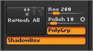
2. You need to have a subtool before you can enable ShadowBox. Duplicate the dog with Tool Subtool Duplicate. Under Tool Subtool, adjust the Res slider to 200. This will control the density of the meshes created with ShadowBox. Make sure Transparency is on in the sidebar. Now click the Tool Subtool ShadowBox button to enable ShadowBox (Figure 10-53).
Figure 10-53: The Res slider and the shadowbox button are found under the Tool Subtool menu.
3. The ShadowBox will appear. You’ll see that the dog is now converted to a simplified form (Figure 10-54). This is because the ShadowBox will incorporate the current subtool. This allows you to further edit a shape using ShadowBox if you desire. In this case you will create a new shape, so clear the ShadowBox using Ctrl+click-drag. ShadowBox is based on masking, so clearing the mask clears the geometry.
Figure 10-54: ShadowBox will initially try to capture the form of the selected subtool.

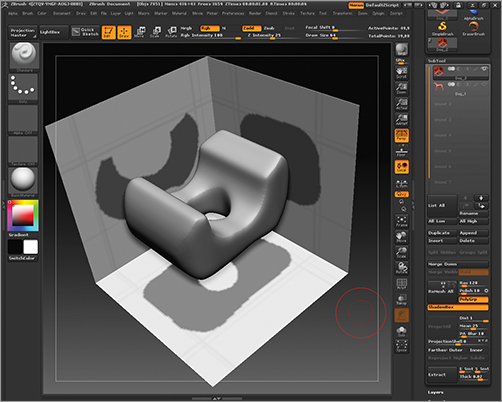
4. ShadowBox works by masking. Drawing masks on each of the box faces will define the shape from that view. Hold down Ctrl and draw a mask on the box, as shown in Figure 10-55. You will further refine this shape by drawing it in the other views.
Figure 10-55: Drawing a mask on the box results in 3D geometry created in the shape of the mask.

5. Draw a mask on the floor of the box to define the shape from the top view (Figure 10-56). Repeat this for the back face of the box (Figure 10-57). By unmasking areas, you can cut negative spaces into the 3D form (Figure 10-58).
Figure 10-56: The floor allows you to define the shape from the overhead view.

Figure 10-57: Each face of the box helps further define the shape of the model.

Figure 10-58: Unmasked areas will become negative spaces.
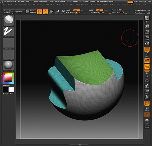
6. When you are done defining your shape, click the ShadowBox button again to exit. The mesh will now be available as a subtool for further sculpting (Figure 10-59). Note that the mesh will be automatically polygrouped in a logical manner.
Figure 10-59: The ShadowBox mesh ready for sculpting. Notice that the model is automatically polygrouped when you exit ShadowBox.

You will now use group loops to isolate the polygroups with an edge loop cut by ZBrush. This allows you to mask and move the grouped areas while maintaining razor sharp angles in the mesh. Figure 10-60 shows a masked area of the mesh moved. Notice how the edges are tagged compared to the looped area.
Figure 10-60: The circles on top were moved by using a mask only to isolate the faces. The bottom used group loops. Notice the far better quality of the edges on the bottom model.

1. Select the Mask Pen brush and, while holding down Ctrl, mask out a section of the side of the object (Figure 10-61). Click Tool Polygroups From Masking to create polygroups based on the masked area (Figure 10-62).
Figure 10-61: Mask an area on the side of the object.
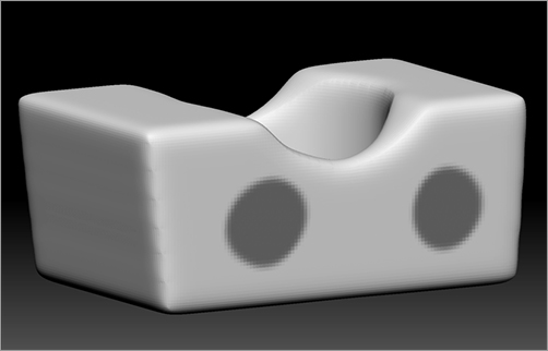
Figure 10-62: Polygroup based on masked area. Notice the ragged edges on the polygroup.

2. The edges of this group will be jagged due to the lower poly count of the object. To cut new edge loops around the polygroups, click Tool Geometry GroupsLoops (Figure 10-63). Figure 10-64 shows the resulting loops.
Figure 10-63: Click the Tool Geometry GroupsLoops button to cut new edge loops around the polygroups.
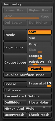
Figure 10-64: The loops cut around the polygroup
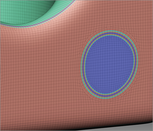
3. Ctrl+Shift-click to isolate the circle group. You can then expand to include the loops in your selection by clicking Tool Visibility Grow (Figure 10-65).
4. Mask the selection, then show visibility on the rest of the model. Invert the mask and use Transpose to move the faces out. The resulting transition will be perfectly sharp (Figure 10-66).
Figure 10-65: Grow Visibility will expand your selection to include the edge loops.

Figure 10-66: Moving the unmasked polys creates a sharp transition impossible without group loops.

That completes the group loops and ShadowBox exercises. You can see how these tools can be invaluable for creating interesting new shapes. ShadowBox is one of the most powerful new additions to ZBrush.
We will now move on to Matchmaker to see another unique tool available in ZBrush 4.
Matchmaker
Matchmaker allows you to conform one shape to another in ZBrush. This is more powerful than a mere shrink wrap operation as Matchmaker will retain some form between the objects. This makes the tool ideal for applying tracery and molding details to objects. You can even use it to lay on pieces of armor or clothing. Keep in mind that Matchmaker works only down the z-axis. You cannot wrap a stroke around corners or bends that turn away from the camera view. Figure 10-67 shows how the Matchmaker effect works only down the line of sight. Figure 10-68 illustrates how the projection will work only in areas that overlap the target object.
Figure 10-67: Matchmaker works by projecting down the line of sight to the object.

Figure 10-68: Any areas that are not over a surface will not be projected.

1. From the accompanying DVD, load the ZTool Matchmaker. This consists of a polysphere and an intricate design created in ShadowBox. Orient the ZTool as shown in Figure 10-69.
Figure 10-69: Load matchmaker1.ztl from the DVD.
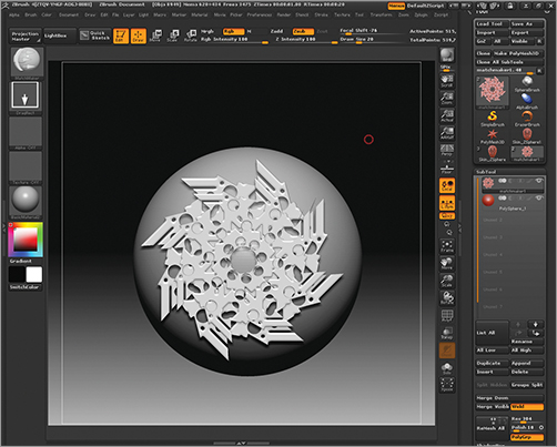
2. From the Brush menu, select the Matchmaker brush. Make sure X Symmetry is off and click-drag from the center of the sphere out. This will conform the shape to the sphere (Figure 10-70).
Figure 10-70: Matchmaker conforms the shape to the sphere.

3. You may want to use Transpose to countersink the shape into the sphere so the fit is more snug (Figure 10-71). Because of the way Matchmaker works, this shape will be conformed perfectly to sit just over the surface of the sphere.
Figure 10-71: Moving the shape closer to the sphere using Transpose

Now that you have seen the tools we will use and the methodology we will follow, let’s move on to something more ornate. In the next exercise we will create a ray gun using ZSketch, ShadowBox, and the hard-surface brushes.