

48 ◾ Advances in Communications-Based Train Control Systems
Crack
present
Crack present
Rail head
Tongue
forms
Tongue forms
Crack
grows
Crack grows
Breakage risks
develop
Breakage
Figure3.2 Typical crack propagation in the head area of rail.
(a)
(b)
(c)
Figure3.3 (a) Broken rail (Data from Wikipedia, http://en.wikipedia.org/wiki/
Rail_inspection.), (b) examples of severe loss of rail foot due to severe corrosion
(Data from Network Rail.), and (c) shelling.
Safe Rail Transport via Nondestructive Testing Inspection ◾ 49
2. Defects due to inappropriate handling and use. ese kinds of defects are
generally due to spinning of train wheels on rails or sudden train brakes, that
is, the wheelburn defect.
3. Rail wear and fatigue defects where three defects are the most frequent: (1) cor-
rugation, (2) bolt hole cracks, and (3) rolling contact fatigue (RCF). Corrugation
is an event strictly correlated to the wearing of the railhead, generated by a
wavelength-xing mechanism related to the train speed, the distance between
the sleepers [27], friction [28], and so on. Bolt hole cracks account for about
50% of the rail defects in joined tracks [29]. RCF damages initiate on or very
close to the rail rolling surface [30] and are much more severe in terms of the
structure integrity [24,30–31].
3.3.3 Fastening Parts Overview
Fastenings are classied into rigid and elastic. Rigid fastenings are used only with
timber or steel sleepers where the rail is connected to the sleeper with bolts or
nails (Figure 3.4a). Elastic fastening systems are widely used and usually consti-
tute toeinsulator, side post insulator, rail pad, shoulder, positive lock-in, and clip
(Figure 3.4b). e toe insulators are installed into the parked position, where they
mechanically hold the side post insulators and pads in place. e clips clamp the
rail onto the rail pads with a spring force per clip of up to 1.25tons. erefore, the
total holding force to rail from each sleeper can be up to 2.5tons.
e defects in fastening parts can be mainly classied into (1) broken bolts or
unhammer nails, (2) gaps between nails and rail, and (3) loosening of a fastening
element. Defects in rail and fastening parts are very severe and, if they are unde-
tected and/or untreated, can lead to rail breaks and derailments. ere are, there-
fore, potential hazards for railway safety.
3.3.4 Critical Place on Rail Network
e critical areas in the rail network, where problems are known to occur and the
probability of defect initiation and propagation is very high, are usually tunnels,
level crossings, bridges, curves, switches, and crossings [33]. e environmental
conditions in the tunnels, such as high level of humidity, cause a rapid growth of
corrosion and other defects. Level crossings are susceptible to corrosion as well, due
to road salt being applied in the areas around the crossing and being further spread
in the tire tread of road vehicles. Access and inspection of tunnels and level crossing
are very dicult, in particular in the case of level crossings, where the level crossing
panels should be removed. With regard to bridges, in Europe there are over 220,000
rail bridges, and most of them are more than 100 years old [34], whereas there are
more than 1290 railway tunnels longer than 1000 km [35]. Switches and crossings
are subject to more intense stresses than linear tracks. Hence, although the types
of defects and required maintenance tasks are similar to those in linear tracks, the
behavior and evolution of switches and crossings defects are dierent than those

50 ◾ Advances in Communications-Based Train Control Systems
in linear tracks, because of the harder stresses. All these parts are considered very
critical because, if they break, this failure makes the train derail. erefore, the
inspection of all these critical places is imperative.
3.4 Rail and Fastening Parts Inspection
e detection of damages in rails and fastening parts at the earliest possible stage
is of paramount importance to the rail transport industry. Catastrophic rail failure
due to growth of structural defects can be avoided by careful inspection and appro-
priately scheduled maintenance. e rst rail inspections have been carried out
Side post
insulator
Rail pad
Positive
lock-in
Sleeper
Shoulder
Toe insulatorClips
(a)
(b)
Figure 3.4 (a) Common rigid (Data from Wikipedia, http://en.wikipedia.org/
wiki/Rail_fastening_system.) and (b) elastic fastening. (Data from Pandrol, The
future of rail fastenings, www.pandrol.com.)
Safe Rail Transport via Nondestructive Testing Inspection ◾ 51
manually by human operators, searching for visual surface anomalies. Nowadays,
the manual inspections remain in use by means of sophisticated handheld equip-
ment. However, the manual inspection is very slow and laborious, and the results
depend on the skill level of the inspector. Relatively recently, rails and fastening
parts have been systematically inspected for internal and surface defects using vari-
ous NDT techniques, such as visual inspection, magnetic induction, eddy currents,
photothermal, and ultrasonics [36–40].
By denition, NDT techniques are the means by which materials and struc-
tures may be inspected without disruption or impairment of serviceability. NDT
is a branch of the engineering science that is concerned with all aspects of the
uniformity, quality, and serviceability of materials and structures. e science of
NDT incorporates many applied engineering technologies for the detection, loca-
tion, and characterization of discontinuities, in items ranging from research speci-
mens to nished hardware and products. NDT has become an increasingly vital
factor in the eective conduct of research, development, design, and manufacturing
programs. A review of current major NDT techniques applicable to railway infra-
structure inspection is presented in Sections 3.4.1 through 3.4.7.
3.4.1 Manual and Automated Visual Rail Inspection
Visual rail inspection examines only surface damage, and it can be conducted
either manually or using automated visual systems. It is the most common and
oldest technique used for rail and fastening parts inspection and is carried out by
trained inspection personnel, who walk along the railways and visually check these
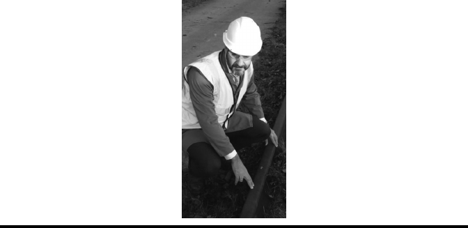
for any visible defect or damage (Figure 3.5). is technique is neither reliable nor
ecient because the chances of human error by missing visible defects are high
Figure3.5 Manual rail inspections expose maintenance personnel to dangers
from passing trains, ying ballast, and projectiles.
52 ◾ Advances in Communications-Based Train Control Systems
and the whole length of the rail needs to be inspected in situ, which is very time
consuming. Additionally, it exposes the personnel walking along the track to carry
out the inspection to danger from moving trains.
To eliminate or reduce, as much as possible, the human error and increase the
inspection speed, automated visual systems have been used. e concept of auto-
mated visual systems is simple, and it is mainly based on the use of a high-speed
camera, capable of capturing video images of the rail as the train moves over it.
Afterward, the acquired images are analyzed automatically. Automated visual
inspection systems are mostly used to measure surface damage and percentage of
wear, pincers position or missing bolts, rail gap, moving sleepers, absence of ballast,
base plate condition in absence of ballast, and so on. e operating speed of these
systems can vary from 60 to 320 km/h, depending on the type of inspection carried
out and resolution required.
3.4.2 Liquid Penetrant Rail Inspection
Liquid penetrant is a visual technique based on the use of special dyes that are
spread over the area of interest for inspection, usually a weld. e dye is applied
on the cleaned surface of the component to be inspected and allowed to dwell for
a few minutes. Once the dye has been allowed to dwell for a sucient amount
of time, the excess dye is wiped away and the developer is applied. If there is
a surface defect present, such as a crack or small pits, then the dye that has
leaked inside will ow back out after the developer has been applied providing
a clear visible indication of the defect. Liquid penetrant is a time-consuming
process carried out manually by certied inspection personnel. e technique
is extremely sensitive to very small defects only a few millimeters in length and
depth but requires thorough cleaning of the surface to be inspected before it can
be used [41]. In the case of railways, the technique can be used to inspect welds of
rails. e inspection is relatively fast but, due to the large number of components
to be inspected, considerable time is required. Only surface-breaking defects are
detectable with this technique.
3.4.3 Ultrasonic Rail Inspection
e current existing ultrasonic rail defect detection techniques and systems have
limitations in terms of the inspection/monitoring reliability over the entire rail sec-
tion, mainly concentrated on the rail head. e ultrasonic testing is applied using
the ultrasonic vehicles and the walking stick probes only cover defects that are
located in the head area, the web, and the part of the foot directly beneath the rail
web (Figure 3.6). is is particularly important because a high percentage of rail
breaks are caused by defects that initiate in the foot of the rail (Figure 3.6c) and
remain undetected due to their location and small size.
..................Content has been hidden....................
You can't read the all page of ebook, please click here login for view all page.