

177
Chapter 9
Networked Control
fora Group of Trainsin
Communications-Based
Train Control Systems
with Random
Packet Drops
Bing Bu, F. Richard Yu, and Tao Tang
Contents
9.1 Introduction ............................................................................................. 178
9.2 Related Work ...........................................................................................179
9.3 Trains’ Control in CBTC Systems ............................................................180
9.3.1 Communication Procedures with Packet Drops ...........................180
9.3.2 Trains’ Control System and Equivalent NCS ................................181
9.3.2.1 Trains’ Control System in CBTC ...................................181
9.3.2.2 Equivalent NCS ..............................................................183
9.3.3 Analytical Formulation of CBTC .................................................184
9.4 Packet Drops in Train–Ground Communications ...................................186
9.4.1 Packet Drops due to Random Transmission Errors ....................... 186
9.4.2 Packet Drops due to Handover .....................................................187
9.4.2.1 Handover Time ..............................................................187
178 ◾ Advances in Communications-Based Train Control Systems
9.1 Introduction
Rail-guided transport systems have attracted more and more attention, because
they can provide greater transport capacity, superior energy eciency, lower car-
bon emission, and outstanding features of punctuality and safety compared with
other mass transit methods. e traditional rail system is a track-based train control
system, which uses track circuit to coarsely determine the location of a train to
transmit unidirectional ground–train control information. e coarse train posi-
tioning and low unidirectional communication throughput lead to low line capac-
ity in TBTC rail systems. e typical minimum headway which is the time interval
between two neighboring trains of TBTC is several minutes [1].
As a modern successor to TBTC, CBTC systems use continuous, high- capacity,
bidirectional train–ground communication to transmit status and control com-
mands of trains to realize automatic train control functions. e line capacity can
be increased. e typical minimum headway of CBTC is 90s or even less [1,2].
For urban transit systems, WLANs are commonly used due to the open stan-
dards and the available commercial o-the-shelf equipment [3]. Numerous WLAN-
based CBTC systems have been deployed around the world, such as Beijing Metro
Line 10 from Siemens [4] and Las Vegas Monorail from Alcatel [5]. However,
WLANs are not originally designed for high-speed scenario; random transmission
delays and packet drops are inevitable in train–ground communication.
Although the two key technologies of CBTC systems, trains’ control and train–
ground communication, are closely related, by now they are designed independently.
9.4.2.2 AP’s Coverage Area .........................................................188
9.4.2.3 Overlapping Coverage Area ............................................ 191
9.4.2.4 Rate of Packet Drops Introduced by Handovers .............191
9.5 Trains’ Control in CBTC with Packet Drops ...........................................193
9.5.1 Currently Used Control Scheme in CBTC Systems ...................... 193
9.5.2 States Estimation under Packet Drops ..........................................194
9.5.3 Eects of Packet Drops on the Stability of the Trains’
ControlSystem .............................................................................197
9.5.4 Eects of Packet Drops on the Performances of the Trains’
Control System .............................................................................198
9.5.5 Two Proposed Novel Control Schemes .........................................199
9.6 Field Test and Simulation Results ............................................................201
9.6.1 Field Test Results on the Packet Drop Rate ..................................201
9.6.2 Design of the Closed-Loop Control Systems .................................202
9.6.3 Simulation Results of Trains’ Control System Impacted by
Packet Drops.................................................................................203
9.7 Conclusion .............................................................................................. 208
References .........................................................................................................210
Networked Control for a Group of Trains ◾ 179
e requirement of trains’ control on the quality-of-service (QoS) of train–ground
communication and the impact of transmission errors on the performance of trains’
control are still not clear. e separated design method limits the performance
improvement of CBTC systems.
In this chapter, we integrate the design of trains’ control and train–ground
communication through modeling the control system of a group of trains in CBTC
as a networked control system (NCS). We study the packet drops in CBTC system,
introduce packet drops into the NCS model, analyze their impact on the stability
and performance of CBTC systems, and propose two novel control schemes to
improve the performances of CBTC system with random packet drops. e dis-
tinct features of this chapter are as follows:
1. We analyze packet drops in CBTC, caused by random transmission errors
and handovers. e packet drop rate is formulated and related to handovers.
e analytical results are well in line with the eld test results.
2. Unlike the existing works that only consider a single train, we consider a
group of trains in CBTC systems to improve the performances of CBTC.
3. We model the CBTC system with a group of trains as an NCS with random
packet drops and analyze their impact on the stability and performances of
CBTC.
4. We propose two control schemes for CBTC to minimize the energy con-
sumption by reducing unnecessary traction and brake forces, to shorten the
headway by decreasing distance uctuation of trains under packet drops.
5. Extensive eld test and simulation results are presented to show that our pro-
posed schemes can provide less energy consumption, better riding comfort-
ability, and higher line capacity compared to existing scheme.
e rest of this chapter is organized as follows: e related work is studied in
Section 9.2. An introduction to CBTC systems is given in Section 9.3. e system
to control a group of trains in CBTC is modeled and formulated as an NCS. Packet
drops in CBTC systems are studied in Section 9.4. e eect of packet drops on the
stability and the performances of trains’ control are investigated and two control
schemes to improve system performances are proposed in Section 9.5. Field test
and simulation results are presented and discussed in Section 9.6. is chapter is
concluded in Section 9.7.
9.2 Related Work
By now, the trains’ control and train–ground communication in CBTC systems are
designed independently. e control of a group of trains in CBTC does not con-
sider too much of the train–ground communication issues. e traditional method
is used [6–11]. A single train is usually considered based on the assumption that the
180 ◾ Advances in Communications-Based Train Control Systems
distance between adjacent trains is long enough to ignore the interaction between
them. However, this assumption does not hold in CBTC, which has a very tight
headway. If a train’s status cannot be sent to the train behind it in time due to trans-
mission errors, the following train may need to trigger a brake or even emergency
brake to ensure safety. A chain reaction might occur in the following trains, which
seriously impairs the line capacity.
Moreover, traditional criteria are used in the design of train–ground communi-
cation system in CBTC, such as network capacity/throughput. Dierent schemes
are proposed in [12–15] to improve the latency, availability, or throughput of train–
ground communication. However, recent works in cross-layer design show that
maximizing capacity/throughput does not necessarily benet the upper layer which
is train control in CBTC [16–21].
Our work is motivated by recent researches on NCS. NCS is a feedback control
system wherein the control loops are closed through a real-time network [22]. e
two main focuses in NCS-related researches are the eect of transmission delays
and packet drops on the stability and the performance of control system [22–28].
In our chapter, the system to control a group of trains in CBTC is modeled as an
NCS.
is work is also stimulated by researches on a platoon of vehicles’ control in
highway [29,30] because the control objectives of a string of vehicles, to minimize
the space, velocity, and applied force errors [31], are similar to those of a group of
trains in rail transit system.
9.3 Trains’ Control in CBTC Systems
In this section, we rst describe an overview of CBTC systems with packet drops.
en, we present the system to control a group of trains. At last, we model the trains’
control system in CBTC as an NCS with packet drops in both uplink and downlink
transmissions, followed by the analytical formulation of the CBTC system.
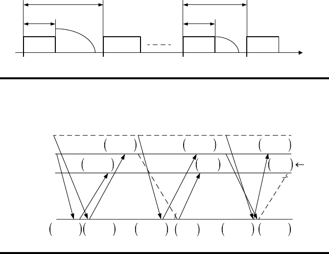
9.3.1 Communication Procedures with Packet Drops
A group of running trains on a line is depicted in Figure 9.1. e position and speed
of the
i
th train at the beginning of the
k
th period are designated as
s
k
i
and
v
k
i
, respec-
tively. e length of the
i
th train is dened as
l
i
. e distance between the tail of the
i
th train and that of the
(1)
i
−
th train is dened as
d
k
i
.
ere is no direct or indirect data transmission among trains in CBTC systems.
e following train can only get the status of the preceding train through LMAs
received from ZC. Each train can get its own status precisely and timely through
onboard odometer and speedometer. e communication procedures between ZC
and trains with packet drops are illustrated in Figure 9.2. At the beginning of the
()
k
−
1 th period, the
()
i
−
2 th,
()
i
−
1 th, and
i
th trains send status to ZC separately.
Networked Control for a Group of Trains ◾ 181
In the
()
k
−
1 th period, there is no packet loss. On receiving the status of the
(1)
i
−
th
train, ZC sends
s
k
i
−
−
1
1
and
v
k
i
−
−
1
1
as LMA to the
i
th train and
s
k
i
−
−
1
2
and
v
k
i
−
−
1
2
are sent as LMA
to the
()
i
−
1 th train.
Suppose that the packet from the
()
i
−
1 th train to ZC is dropped in the
k
th
period. For safety, ZC assumes that the
()
i
−
1 th train keeps still since the last time
ZC received its status. ZC uses the last available location of the
()
i
−
1 th train with
a zero speed as LMA for the
i
th train.
In the
(1)
k
+
th period, the downlink packet from ZC to the
i
th train is lost.To
ensure safe movement, the
i
th train assumes that the
()
i
−
1 th train maintains motion-
less since last time the
i
th train received LMA from ZC. e estimated LMA is used
to calculate the speed/distance prole of the train.
9.3.2 Trains’ Control System and Equivalent NCS
9.3.2.1 Trains’ Control System in CBTC
e control system includes a group of trains, a ZC, and the network between ZC
and trains, which is illustrated in Figure 9.3.
Train i Train i − 1 Train 2 Train 1
Travel
direction
l
i
d
k
i
l
2
d
k
2
s
k
i
v
k
i
s
k
i−1
v
k
i−1
s
k
2
v
k
2
s
k
1
v
k
1
Figure9.1 Train following model.
ZC
k
−
1
k
k
+
1
(
i−2)th train
(
i−1)th train
i
th train
Est
.
Est.
s
k−1
, v
k−1
i−1 i−1
s
k−1
, v
k−1
i−1 i−1
s
k−1
, 0
i−1
s
k−1
, 0
i−1
s
k−1
, 0
i−1
s
k−1
, v
k−1
i−2 i−2
s
k−1
, v
k−1
i−2 i−2
s
k+1
, v
k+1
i−2 i−2
s
k+1
, v
k+1
i−2 i−2
s
k+1
, v
k+1
i−1 i−1
s
k
, v
k
i−2 i−2
s
k
, v
k
i−2 i−2
Figure9.2 Communication procedure between ZC and the running trains with
packet drops.
..................Content has been hidden....................
You can't read the all page of ebook, please click here login for view all page.