

65
Chapter 4
Modeling of the
Wireless Channels in
Underground Tunnels for
Communications-Based
Train Control Systems
Hongwei Wang, F. RichardYu,Li Zhu,
and Tao Tang
Contents
4.1 Introduction .............................................................................................. 66
4.2 Real Field CBTC Channel Measurements .................................................67
4.2.1 Measurement Equipment ................................................................ 67
4.2.2 Measurement Scenario ....................................................................68
4.3 Finite-State Markov Chain Channel Model ...............................................69
4.3.1 FSMC Model ..................................................................................69
4.3.2 Determine the SNR-Level resholds of the FSMC Model ............72
4.3.3 Determine the Distribution of SNR ...............................................74
4.4 Real Field Measurement: Results and Discussions ......................................76
4.5 Conclusion .................................................................................................79
References ...........................................................................................................79
66 ◾ Advances in Communications-Based Train Control Systems
4.1 Introduction
Building a train–ground wireless communication system for communications-
based train control (CBTC) is a challenging task. As urban rail transit systems are
mostly deployed in underground tunnels, there are a large amount of reections,
scattering, and barriers that severely aect the propagation performance of wireless
communications. Moreover, due to the available commercial o-the-shelf equip-
ment, wireless local area networks (WLANs) are often adopted as the main method
of train–ground communications for CBTC systems. However, most of the cur-
rent IEEE 802.11 WLAN standards are not originally designed for the high-speed
environment in tunnels [1]. Furthermore, the fast movement of trains will cause
frequent handos between WLAN access points (APs), which can severely aect
the CBTC performance.
Modeling the channels of urban rail transit systems is very important to design
the wireless networks and evaluate the performance of CBTC systems. ere are
some previous works on radio wave propagation in urban rail transit systems.
Apath loss model of tunnel channels is given in [2], which describes the character-
istics of the large-scale fading. e authors of [3] present the propagation charac-
teristics based on real environment measurements in Madrid subway. A two-layer
multistate Markov model is presented in [4] for modeling a 1.8 GHz channel in
urban Taipei city. Based on the Winner II physical layer channel model parameters,
the authors of [5] propose a channel model for high-speed railway.
Although some excellent works have been done on modeling channels, most
of them do not consider the unique characteristics of CBTC systems, such as high
mobility speed, deterministic moving direction, and accurate train location infor-
mation. In this chapter, we develop a nite-state Markov channel (FSMC) model
for tunnel channels in CBTC systems. FSMC models have been widely accepted in
the literature as an eective approach to characterize the correlation structure of the
fading process, including 1.8 GHz narrow-band channels [4], high-speed railway
channels [5], satellite channels [6], indoor channels [7], Rayleigh fading channels
[8], Rician fading channels [9], and Nakagami fading channels [10]. Using FSMC
models, a variety of analytical results of system performance can be derived, includ-
ing channel capacity [11], throughput [12], and packet error distribution [13].
To the best of our knowledge, FSMC models for tunnel channels in CBTC
systems have not been studied in previous works. erefore, there is a strong moti-
vation to develop an FSMC model for tunnel channels in CBTC systems. Some
distinct features of the proposed channel model are as follows:
◾ e proposed FSMC model is based on real eld CBTC channel measure-
ments obtained from the business operating Beijing Subway Changping Line.
◾ Unlike most existing channel models, which do not use train location infor-
mation, the proposed FSMC channel model takes train locations into account
to have a more accurate channel model.
Modeling of the Wireless Channels in Underground Tunnels ◾ 67
◾ e distance between the transmitter and the receiver is divided into intervals,
and the FSMC model is applied in each interval.
◾ Lloyd–Max technique [14] is used to determine the signal-to-noise ratio
(SNR)-level boundaries in the proposed FSMC model.
◾ e accuracy of the proposed FSMC model is illustrated by the simulation
results generated from the model and the real eld measurement results.
eeects of dierent parameters are also discussed.
e rest of this chapter is organized as follows: Section 4.2 describes the real eld
measurement conguration and scenario. Section 4.3 introduces the FSMC model.
en, Section 4.4 presents the real eld measurement results and discussions.
Finally, Section 4.5 concludes the chapter.
4.2 Real Field CBTC Channel Measurements
e objective of the real eld CBTC channel measurements is to get the real eld data
of WLAN propagation in tunnels under real conditions of the subway line, which will
be used to build an FSMC model. In this section, we present the measurement equip-
ment and the measurement scenario in our real eld CBTC channel measurements.
With this objective, the preparation of the measurements consists of two parts
as follows:
1. We need to make sure that the conguration of the measurements is the same
as business operating subway lines, including the choice of antennas, the loca-
tion of antennas, and the settings of the transmitter and the receiver.
2. We need to develop a measurement method to map channel data, including
the signal strength and SNR, to the location of the receiver, which will be
used in our research that takes train locations into account to have a more
accurate channel model.
4.2.1 Measurement Equipment
Two Cisco 3200 routers are used in our measurements. One is set as the AP,
whereas the other one is set as the mobile station (MS). Both of them are set to work
at the frequency of 2.412 GHz, which is also called channel 1. e output power
of the AP is set as 30 dBm. e AP is located on the wall of the tunnel, whereas
the MS is located on the measurement vehicle. e transmitting antenna is a Yagi
antenna connected with the AP, which is directional and vertically polarized. e
half power beam width (HPBW) is 30° and the gain of Yagi antenna is 13.5 dBi. In
addition, the Shark-n antenna is applied as the receiving antenna connected with
the MS, which is also directional and vertically polarized. e HPBW is 40° and
the gain of Shark-n antenna is 10 dBi.
68 ◾ Advances in Communications-Based Train Control Systems
e location of the receiver is obtained through a velocity sensor installed
onthe wheel of the measurement vehicle, which can detect the real-time velocity,
and theresolution of position is millimeter per second. Figure 4.1 shows the mea-
surement equipment used in our real eld measurements.
4.2.2 Measurement Scenario
e measurements were performed in Beijing Subway Changping Line, where the
cross section of the tunnel is rectangular. e cross section of the tunnel and the
locations of antenna are shown in Figure 4.2. e height of the tunnel is 4.91 m
and the width is 4.4 m. e transmitting antenna is located 0.15 m below the tun-
nel roof. e receiving antenna is set on the top of a measurement vehicle. As the
threshold of the receiver is −90 dBm, the coverage of one AP is about 0–500 m,
which is also the experimental zone in our measurements. e tunnel where we
performed the measurement is a section of straight tunnel. Figure 4.3 shows the
cross section of the tunnel near Nanshao station of Beijing Subway Changping
Line, the Shark-n antenna, the Yagi antennas, and the AP set on the wall. We
performed measurements in the tunnel of Beijing Subway Changping Line for
20times so that enough data can be captured.
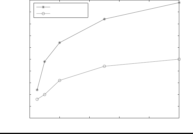
0 20 40 60 80
100
0.020
0.025
0.030
0.035
0.040
0.045
0.050
0.055
0.060
0.065
0.070
Interval
MSE
FSMC four states
FSMC eight states
Figure 4.1 Measurement equipment used in the real eld CBTC channel
measurements.

Modeling of the Wireless Channels in Underground Tunnels ◾ 69
4.3 Finite-State Markov Chain Channel Model
To capture the characteristics of tunnel channels in CBTC systems, we dene chan-
nel states according to the dierent SNR levels received and use an FSMC to track
the state variation. In this section, we rst describe the FSMC model, followed by
the determination of key model parameters, including SNR levels and SNR distri-
bution. Table 4.1 illustrates the notions of symbols used in this chapter.
4.3.1 FSMC Model
e SNR range of the received signal can be partitioned into
N
nonoverlapping
levels with thresholds
{,
=0,1,2,3,...,
}Γ
n
nN
, where
Γ
0
and
Γ
N
can be measured.
e time axis is divided into slots of equal duration. Let
γ
k
denote the channel state
in time slot
k
.
γ
kn
s
=
when the SNR of the received signal belongs to the range
(ΓΓ
nn
−
1
,)
. en the received SNR can be modeled as a random variable
γ
evolving
according to a nite-state Markov chain, and the transition probability
p
nj
,
can be
shown as follows:
p
Pss
nj
rk nk j
,
1
{}
===
+
γγ
|
(4.1)
Transmitting antenna
Receiving antenna
Track
4.4 m
4.91 m
3.8 m
0.15 m
Figure4.2 Tunnel section and deployment of antennas in the measurement.
..................Content has been hidden....................
You can't read the all page of ebook, please click here login for view all page.