
AutoCAD and AutoCAD LT come with a large number of linetypes and hatch patterns. However, when these do not serve your particular needs, you can create your own linetypes and hatch patterns. You can then use them in your drawings in the same way that you use the linetypes and hatch patterns that come with the software.
Linetypes are useful whenever you don't want a continuous linetype. They apply not only to lines, but also to polylines, arcs, ellipses, wireframes, and solids — in fact, to most objects. You use hatch patterns to fill in closed (or almost closed) areas. Hatch patterns often represent textures or materials.
There are two types of linetypes: simple and complex. Simple linetypes consist of only dashes and dots. Complex linetypes usually have dashes and/or dots, but also contain text and/or shapes.
The default linetype file is acad.lin for AutoCAD and acadlt.lin for AutoCAD LT. You can add your own linetype definitions to this file or create your own linetype files. Linetype files are text files and must have a .lin file extension. Of course, be sure to make a backup copy of acad.lin or acadlt.lin before you edit it. You commonly use Notepad to edit a linetype file.
In the syntax for creating simple linetypes, each linetype is defined by using two lines of text. The first line contains the linetype name and an optional description, formatted as follows:
*linetype name[, description]
Here are some points to remember:
Always start the definition with an asterisk.
The name and description of a linetype is limited to 279 characters total. However, descriptions longer than 45 characters are hard to read in the Linetype Manager and other dialog boxes and drop-down lists.
If you include a description, precede it with a comma.
The second line of the linetype syntax is its definition. With simple linetypes, you're limited to dashes, dots, and spaces, which are measured in units and specified as follows:
A dash is indicated by a positive number.
A dot is indicated by a 0.
A space is indicated by a negative number.
Each item is separated by a comma, there are no spaces; you must have a minimum of 2 dashes, dots or spaces items and can have up to a total of 12.
Each line must start with the letter A.
The following definition creates a line with two dashes of 0.25 units, followed by two dots, all separated by spaces of 0.1 units.
*seeingdouble, Future hedge line
A,.25,−.1,.25,−.1,0,−.1,0,−.1
The result is shown in Figure 31.1.
If you feel confident, you can even create linetypes on the fly, using the command-line form of the LINETYPE command. Type -linetype
Tip
If your linetype definition will include both dashes and dots, you'll get the best results when you start the linetype definition with a dash. Starting the definition with a dash is a matter of aesthetics, perhaps, but such a line connects better to other lines.
STEPS: Creating a Simple Linetype
Create a drawing by using the
acad.dwtoracadlt.dwttemplate.Save your drawing as
ab31-01.dwgin yourAutoCAD Biblefolder.In Windows XP, choose Start

Type the following:
*3dotsandadash, temporary fencingA,.5,−.25,0,−.1,0,−.1,0,−.25Press Enter after the last line. Save the file as
ab31-01.linin yourAutoCAD Biblefolder and close Notepad.In your drawing, choose Home tab
Click Continuous in the Linetype column to open the Select Linetype dialog box. Click Load.
In the Load or Reload Linetypes dialog box, click File. In the Select Linetype File dialog box, find
ab31-01.linin yourAutoCAD Biblefolder, choose it, and click Open.Back in the Load or Reload Linetypes dialog box, choose
3dotsandadashand click OK.Again, in the Select Linetype dialog box, choose
3dotsandadashand then click OK. The layertfencenow shows the correct linetype. Click Set Current and then click OK.Start the LINE command and turn on Ortho Mode. Draw any line to see the linetype. Save your drawing. The linetype should look like Figure 31.2.
A complex linetype includes either shapes or text in the linetype definition. Complex linetype definitions are similar to those for simple linetypes, except that they add a definition for a shape or text. Figure 31.3 shows an example of each type.
Shapes are covered in the next chapter. At this point, you only need to know that shapes are contained in files with the file extension .shx.
The first line of the linetype definition is the same as for simple linetypes. The second line of the definition can contain all the same features as those for a simple linetype. However, you add the special shape or text definition in square brackets:
Syntax for shapes.
[shapename,shxfilename,details]Syntax for text.
["text string", textstyle, details]
details refers to an optional series of rotation, scale, and offset specifications that you can add to the definition. Table 31.1 describes these specifications.
The following complex linetype definition uses a shape and has no details:
*TEMPFENCE, FENCE SHAPE AND DASH
A,.5,−.25,[FENCE,"C:AUTOCAD BIBLEFENCE.SHX"],−.5
The specification for the shape is simply part of the rest of the definition that includes a dash and spaces before and after the shape. The shape is enclosed in both commas and square brackets. The first part of the shape definition is the name of the shape (which is defined in the shape's definition file), and the second part is the name of the shape file. In this case, the shape file is not in thesupport-file search path, so the entire path needs to be specified. Don't forget to use quotation marks around the shape filename if the folder name or filename contains embedded spaces.
Tip
Note that the space after the shape (created with the −.5 code) is larger than the space before it (created with the −.25 code). You need to allow for the space that the shape takes up. This is largely a matter of trial and error, but if you know the shape definition well, you can make a good estimate. If you need to go back and change the linetype definition, don't forget to reload the linetype (using the Load option).
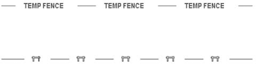
The following complex linetype definition uses text and has no details:
*TFENCE, DASH & TEXT
A,.5,−.25,["TEMP FENCE",FENCE],−1.5
Again, the specification for the text is placed within a linetype definition that includes a dash and spaces. The first part of the text definition is the text string, which is always in quotation marks. The second part of the definition is the text style. As with the previous linetype definition containing a shape, the space after the text is larger than the space before in order to leave enough room for the text. You must define the text style in the drawing before you load the linetype.
Table 31.1 lists the details that you can add to both the shape and text parts of complex linetype definitions.
Table 31.1. Optional Details for Shapes and Text in Complex Linetype Definitions
Detail | Syntax | Description |
|---|---|---|
Relative rotation |
| Rotates the shape or text relative to the angle of the line that you draw. |
Absolute rotation |
| Rotates the shape or text based on the World Coordinate System, regardless of the angle of the line. Because the default is a relative rotation of 0, you can use absolute rotation to keep the text facing upright, regardless of the direction of the line. |
Scale |
| Scales the text or shape. This scale is multiplied by any scale that is contained in a shape definition or height in a text style. If you use a text style with a height of 0, this scale number defines the text's height. |
X offset |
| A positive number moves the shape or text toward the endpoint of the line. A negative number moves the shape or text toward the start point of the line. You can use an X offset to place a shape or text along a continuous linetype. You can also use an X offset to adjust the spacing of a shape or text between dashes, instead of changing the spaces before or after the dashes. |
| Moves the shape or text perpendicular to the direction of the line. A positive number moves the shape or text up if the line is drawn from left to right. Use a Y offset to center text and shapes along a linetype. | |
[a] * Although using an absolute rotation of 0 might sound like a good idea for complex linetypes with text, if you use the linetype at varying angles or on curves, you may find that the text shifts to an undesirable location due to the text's justification point. | ||
Here is a definition that includes a shape with a scale and a Y offset:
*TEMPFENCE, FENCE SHAPE AND DASH
A,.5,−.25,[FENCE,"C:AUTOCAD BIBLEFENCE.SHX",S=.025,Y=−.07],−.5
This shape definition scales the shape to 0.025 of its original size. This results in the linetype shown in Figure 31.4. Of course, in order to scale the shape, you need to know its original size. You can use the SHAPE command to insert a shape and get an idea of what it looks like. In this case, the shape's original definition is much too large for a linetype and needs to be scaled down.
The shape definition also moves the shape in the minus Y direction by 0.07 units. This centers the shape nicely within the linetype.
Warning
When you create drawings using shapes or custom fonts, as in the case of complex linetypes, you need to include the shape files or font files when you distribute the drawings to others.
By including more involved shapes in a complex linetype and not much else, you can create a linetype that is mostly a series of shapes displayed one after the other. You can create some interesting effects in this way.
You can find several complex linetypes at the end of the acad.lin or acadlt.lin linetype definition file. Look at their definitions and try them out to get ideas for your own complex linetypes. The Express Tools installation (in AutoCAD only) has a command, MKLTYPE, that automatically creates linetypes, even complex ones. Choose Express Tools tab
Note
To find the location of acad.lin or acadlt.lin, choose Application Button
Note
The drawing used in the following exercise on creating a complex linetype, ab31-a.dwg, is in the Drawings folder on the DVD.
STEPS: Creating a Complex Linetype
Open
ab31-a.dwgfrom the DVD.Save the file as
ab31-02.dwgin yourAutoCAD Biblefolder. This drawing is a simple plan for a trailer park.Choose Home tab
In Windows, open Notepad, and type the following:
*TV, Buried television cableA,.5,-.5,["TV",TVCABLE,S=.3,X=-.1,Y=-.15],-.75
Save the file in your
AutoCAD Biblefolder asab31-02.lin.Open the Layer Properties Manager. Choose
Buried_cableand click its Continuous linetype in the Linetype column. In the Select Linetype dialog box, choose Load. Click File. Findab31-02.linin yourAutoCAD Biblefolder, choose it, and click Open.In the Load or Reload Linetypes dialog box, choose TV and click OK. Do the same in the Select Linetypes dialog box. Click Set Current. Click OK.
Choose Home tab
Draw some lines or polylines. Zoom in to see the linetype more clearly. Figure 31.5 shows the resulting linetype.
Save your drawing.
Hatch patterns are sets of line patterns that are used to fill an enclosed area. Although the part of the hatch pattern definition that defines each line is similar to a linetype definition, you also need to specify the angle and spacing of the lines. You cannot include text or shapes in hatch patterns.
Hatch patterns are stored in files with a file extension of .pat. The acad.pat or acadlt. pat file includes a large number of hatch patterns. You can add to or edit this file, or create your own .pat file. As always, don't forget to make a copy of acad.pat or acadlt.pat before you edit it. When creating your own .pat file, remember the following:
Note
To find the location of acad.pat or acadlt.pat, choose Application Button
The syntax for hatch patterns is as follows:
*pattern-name[, description]
angle, x-origin,y-origin, delta-x,delta-y [, dash1, dash2, ...]
Here are some general points for hatch-pattern definitions:
The pattern name cannot have spaces, but you can create a custom hatch pattern in which the filename and pattern name have a space.
The description is optional; if you include one, precede it with a comma.
You can have more than one definition line (the second line in the syntax I just showed), creating sets of hatch definitions that combine to create the hatch pattern.
Each definition line can be no more than 80 characters.
You can include a maximum of six dash specifications (which include spaces and dots).
You can add spaces in the definition lines for readability.
Table 31.2 describes the features of a hatch-pattern definition.
Table 31.2. Hatch-Pattern Definitions
Specification | Explanation |
|---|---|
Angle | Defines the angle of the lines in the hatch pattern. If you also specify an angle in the Hatch and Gradient dialog box in AutoCAD or Hatch dialog box in AutoCAD LT (when you are placing the hatch), the two angles are added. For example, if a hatch pattern defines lines at 105 degrees and you specify a hatch angle of 30 degrees, you end up with lines running at 135 degrees. |
X-origin | Specifies the X coordinate of the base point of the hatch pattern. Your hatch probably won't go through 0,0; however, this point lines up sets of lines in hatch patterns, as well as aligning hatch patterns in different areas. Because all hatch patterns are calculated from the base point, they're always aligned, no matter where they actually appear in the drawing. |
Y-origin | Specifies the Y coordinate of the base point of the hatch pattern. |
Delta-x | Specifies the offset of successive lines. This applies only to dashed lines and is measured along the direction of the lines. Specifying a delta-x staggers each successive line by the amount that you specify so that the dashes don't line up. |
Delta-y | Specifies the distance between lines, measured perpendicular to the direction of the lines. This applies to both continuous and dashed lines. |
Dash | Defines a noncontinuous line, using the same system as linetype definitions: positive for a dash, negative for a space, and 0 for a dot. |
The hatch pattern shown in Figure 31.6 is the simplest form of hatch pattern.
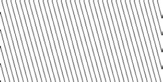
Although you could specify this simple hatch pattern in the Hatch and Gradient dialog box (the Hatch dialog box if you are using AutoCAD LT) by specifying a user-defined hatch with an angle and spacing, the example that follows shows the syntax clearly. The lines are at an angle of 105 degrees; the hatch pattern starts at 0,0; and the spacing between the lines is 0.5 units. The lines are continuous.
*ftrailer, proposed future trailers
105, 0,0, 0,0.5
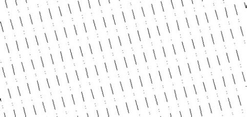
By adding one level of complexity, you can make the lines in the hatch pattern noncontinuous, as follows:
*ftrailer, proposed future trailers
105, 0,0, 0,0.5, .5,−.25,0,−.1,0,−.25
Note that this definition uses the maximum of six dash specifications (the dash, space, dot, space, dot, and space).
A close-up of this hatch pattern is shown in Figure 31.7.
If you add a delta-x of 0.25, the lines in the pattern are staggered by 0.25 units, along the direction of the lines, as shown in this code and in Figure 31.8:
*ftrailer, proposed future trailers
105, 0,0, 0.25,0.5, .5,−.25,0,−.1,0,−.25
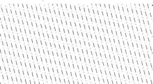
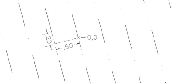
You might wonder why the pattern staggers downward after adding a positive delta-x. The answer is that the direction of the lines (in this case, 105 degrees) becomes the X axis for this calculation. Figure 31.9 shows a zoomed-in display of the hatch pattern around 0,0, which is the base point. The hatch pattern is being generated up and to the left. The first line starts at 0,0, and the second line starts to the left by 0.5 units (the delta-y) and up by 0.25 units (the delta-x), as shown by the dimensions.
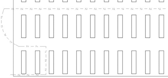
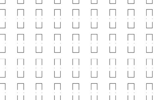
Finally, you can add additional definition lines. One of the definition lines should start at 0,0, but the others may start anywhere. Here is the definition for the pattern in Figure 31.10. It actually creates the shape of the trailers. Although you see the rectangular shape, the hatch pattern is created from four separate lines, two at 0 degrees and two at 90 degrees. Note that the two 0-degree lines are the same, except that they start at different base points. The same is true for the two 90-degree lines.
*trail, whole trailers-proposed
0, 0,0, 0,2, .5,−1
90, 0,0, 0,1.5, .5,−.25,0,−.25,.5,−.5
90, .5,0, 0,1.5, .5,−.25,0,−.25,.5,−.5
0, 0,1.5, 0,2, .5,−1
STEPS: Creating and Using a Hatch Pattern
Create a drawing by using any template.
Save the file as
ab31-03.dwgin yourAutoCAD Biblefolder.In Windows, choose Start
Type the following:
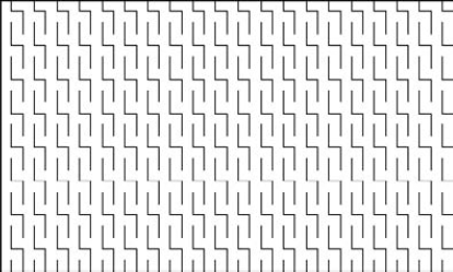
*lightning, interwoven lightning90, 0,0, 0,.5, .5,−.250, −.25,.5, 0,.75, .25,−.2590, −.25,.5, 0,.5, .5,−.25Press Enter after the last line. Save the file as
lightning.patin yourAutoCAD Biblefolder. Close Notepad.If you haven't already done so, you need to add your
AutoCAD Biblefolder to thesupport-file search path. Choose Application ButtonChoose Home tab
Choose Home tab
Click the Ellipsis (...) button to the right of the Custom Pattern text box. Choose the
lightning.patfile that you just created. Click OK.Choose Add: Select Objects and pick the rectangle in your drawing. Press Enter. Click OK. The rectangle fills with the lightning hatch, as shown in Figure 31.11.
Save your drawing.
Check out the acad.pat or acadlt.pat file for some ideas on how to create your own hatch-pattern definitions.
In this chapter, you discovered how to create your own linetypes and hatch patterns. You read about the following:
Creating simple linetypes that contain only dashes, dots, and spaces
Making complex linetypes that include shapes and text
Constructing your own hatch patterns that are made up of sets of lines
In the next chapter, you read about how to create shapes and fonts.