
The AutoCAD database connectivity feature enables you to communicate with an external database from within AutoCAD.
Note
AutoCAD LT does not include the database connectivity feature. This entire chapter applies to AutoCAD only.
Database connectivity is a powerful way to link drawing objects with data and is more flexible than using block attributes. With database connectivity, you can link data in an external database to any object in a drawing. In this chapter, I show you that database connectivity does not have to be as difficult as it often sounds.
Many AutoCAD users maintain databases separately from their drawings. You can work directly with your data by linking the rows of the database tables to objects in your drawings. The drawing objects thus become intelligent and carry these links with them in the drawing. You can also change data, such as a price or a part number, from within AutoCAD, and have that change automatically applied and available in all drawing objects that are linked to that database item. Finally, you can create labels in your drawing, based on the data in the database.
Note
You can link to external Microsoft Excel spreadsheets and comma-delimited (CSV) files in a table. For more information, see Chapter 13. Using that feature, you can view the external data and change it (both in the table and in Excel). Your table always displays the current data in the spreadsheet. However, the external database access feature described in this chapter offers some additional capabilities, such as linking rows of data to objects in your drawing, creating labels, and creating SQL queries.
Many organizations maintain extensive databases of objects that are in their AutoCAD drawings. Manufacturers maintain databases of parts, offices maintain databases of furniture, and so on. You need to keep your drawings and the databases synchronized so that the information in the databases and in the drawings is always accurate and up to date.
The linking of databases and AutoCAD drawings is referred to as external database access. External database access enables you to:
The database connectivity feature works with the following databases:
Microsoft Access
dBASE
Microsoft Excel
Oracle
Paradox
Microsoft Visual FoxPro
SQL Server
After you configure a database, as explained later in this chapter, you can access the data in the database even if you don't have the database program that created the data.
A database is a set of related information, usually maintained by a database-management system (DBMS) — an application that manages databases. A database is stored in the form of a table that contains rows and columns. A row, also called a record, contains one element of data, such as the information for one desk. A column, also called a field, contains the attributes of the data, such as the price.
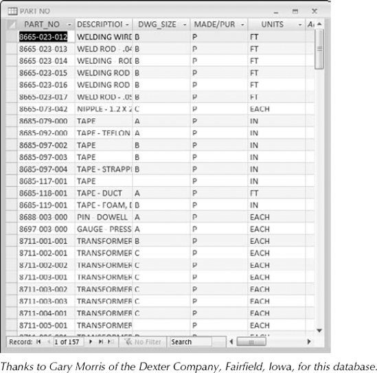
Table 20.1 shows the first three rows of the database used as an example in this chapter.
Table 20.1. A Simple Database Table
Part Number | Description | Dwg Size | Made/Purchased | Units |
|---|---|---|---|---|
8665-023-012 | Welding Wire — 0.030 StainlessB | B | P | FT |
8665-023-013 | Weld Rod — 0.045 Dia Stainless Steel | B | P | FT |
8665-023-014 | Welding — Rod 0.045 Dia S.S. | B | P | FT |
A relational database is a type of database that contains a collection of tables. Each table represents a set of data for a defined use.
Structured Query Language (SQL — pronounced sequel or S-Q-L) was created to provide users with a database language that would be applicable across multiple platforms and database-management programs.
Some database systems use environments, catalogs, schemas, and tables to create a hierarchy of database objects. A database object is simply the term used to specify any of the following SQL objects: environment, catalog, schema, or table.
The environment is the entire database system — the DBMS, the databases it can access, the users, and the programs that can access those databases.
A catalog is a collection of schemas and has the same name as the folder where the database is located.
A schema is a set of tables and other database components. It has the same name as the catalog subfolder where the database tables reside.
You don't need to work with these concepts if your database system does not require or specify it. AutoCAD can connect to an individual table or to a collection of tables stored in an environment, catalog, or schema.
Warning
The 64-bit release of AutoCAD does not support these drivers for connectivity to Microsoft Access and Excel databases. The solution is to use SQL Server instead of the OLE DB driver. For more information, check AutoCAD Help in the AutoCAD 2010 Driver and Peripheral Guide
Database connectivity involves several components that you need to prepare in advance. When they are in place, the connection should go smoothly. In this section, I explain the necessary preparation steps.
The basic steps for starting to work with database connectivity are as follows:
Make sure that you have the ODBC Data Source program from Microsoft.
Arrange your database tables into catalogs (folders) and schemas (subfolders) appropriate for your application, if necessary.
Configure the appropriate database driver by using Microsoft's ODBC (Open Database Connectivity) or OLE DB program.
Configure your data source from within AutoCAD.
Start the dbCONNECT command.
Establish a user access name and password, if required by the database system.
Connect to your data source.
Open the Data View window containing your data table.
Edit the data, if desired.
Link database rows to objects in your drawing.
Create labels based on the data in your drawing, if desired.
To connect to a database, you need to know the type of database-management system that created the database and the structure of the database itself, along with the folders that contain that structure. In the following exercise, you create a simple structure for a Microsoft Access database table.
Note
In this chapter, you cannot do the later exercises without doing the earlier ones. The later exercises depend on the setup and configuration that you create in the earlier exercises.
Note
The file used in the following exercise on creating the structure for the database, ab20-prt.mdb, is in the Drawings folder on the DVD.
STEPS: Creating the Structure for the Database
Right-click Start on the task bar. Choose Explore to open Windows Explorer.
If your
AutoCAD Biblefolder is not displayed in the Folders window, click the plus sign (+) next to the drive containing theAutoCAD Biblefolder.Click the
AutoCAD Biblefolder and choose File
If necessary, in the Folders window, click the plus sign to open the
AutoCAD Biblefolder. You should see the newDatabasesfolder. (If not, press F5 to refresh the Explorer view.)From the DVD, copy
ab20-prt.mdbto theDatabasesfolder that you just created. (Be sure to choose theab20-prt.mdbfile, not theab20-prt.xlsfile.) The.mdbfile is a database of parts. Figure 20.1 shows this database.Because this file is coming from a DVD, you may need to change its read-only property. Still in Explorer, right-click
ab20-prt.mdband choose Properties from the menu. Uncheck Read-Only and click OK.Click the Close button of Explorer to close it.
Note
If you have Microsoft Access 2007, you may want to open this database in Access and convert it to 2007 format. When you open the database, you'll automatically see a dialog box prompting you to convert the file.
To start working with external databases, you must tell AutoCAD how to communicate with your database, called a data source. AutoCAD uses ODBC and OLE DB for this communication. AutoCAD provides a sample Microsoft Access file, called db_samples.mdb in AutoCAD's Sample folder, that you can work with to get started.
First, you must install and configure the ODBC Data Source Administrator. To check if the ODBC Data Source Administrator is installed on your computer, open the Control Panel by choosing Start
Administrative Tools
ODBC Data Sources (32-bit) or Data Sources (ODBC)
Note
You might need to click Switch to Classic View (or Classic View) on the left side of the Control Panel window in order to see these in the Control Panel.
To check if you have the required drivers installed, double-click the ODBC item. In the ODBC Data Source Administrator dialog box, you'll see a list of database application drivers. (A database driver contains information about how to connect to your database.) Check to see that your database application is listed. Click OK to close the dialog box.
In most cases, your operating system will include the ODBC Administrator. If you don't have the ODBC 32-bit Administrator, you need to install the Microsoft ODBC Driver Pack. The ODBC Driver Pack 3.0 (or later) is free from the Microsoft Web site at msdn2.microsoft.com/en-us/data/aa937730.aspx. The MDAC (Microsoft Data Access Components) 2.8 download should provide you with everything you need.
The instructions to set up the database vary according to the drivers that you use. The AutoCAD online help contains help on all supported databases. Look in Help (press F1) and click the Contents tab. Double-click Driver and Peripheral Guide, then click Configure External Databases and select Configure External Databases. Click the Procedures tab and choose the link for your database.
To set up your database by using ODBC, follow these steps:
From the Windows task bar, choose Start
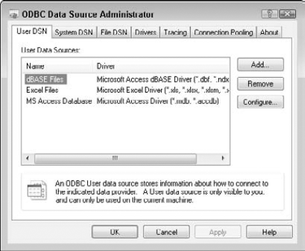
Double-click the Administrative Tools icon, and then double-click the Data Sources (ODBC) item. Windows opens the ODBC Data Source Administrator dialog box, as shown in Figure 20.2.
Click the User DSN tab if it isn't already displayed. Choose Add.
In the Create New Data Source dialog box, choose the driver appropriate for your database and click Finish.
In the ODBC Setup dialog box, which is now titled with the name of the driver that you chose (for example, ODBC Microsoft Access Setup), type a name for your data source in the Data Source Name text box. You can also add a description. In general, this name refers to your database program, not the individual database file.
Click Select and navigate to the folder containing your database. Choose the database file and click OK.
Click OK again in the Setup dialog box.
In the ODBC Data Source Administrator dialog box, your data source is listed with its appropriate driver. Click OK. Close the Administrative Tools window and the Control Panel.
You're now ready to configure your database from within AutoCAD. Follow these steps:
At the command line, type dbconnect

On the dbConnect Manager, right-click Data Sources and choose Configure Data Source from the shortcut menu. In the Configure a Data Source dialog box, type a name representing your database file. Click OK.
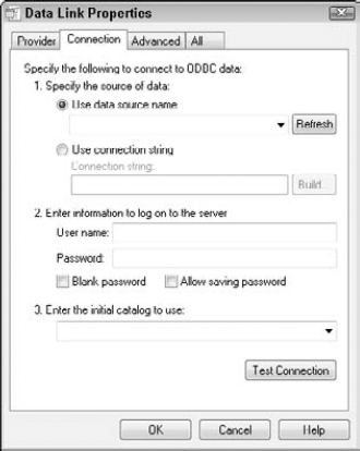
On the Provider tab of the Data Link Properties dialog box, choose Microsoft OLE DB Provider for ODBC drivers. Click Next.
From the Use Data Source Name drop-down list on the Connection tab, choose the name of the data source that you used in the ODBC Setup dialog box, as shown in Figure 20.3.
For server-based databases, enter the user name and password.
Click Test Connection. If you see a message saying
Test Connection Succeeded, click OK. (If not, check your settings as well as the spelling and case of the name of the data source.)Click OK in the Data Link Properties dialog box.
You're now ready to establish a connection between a database and an AutoCAD drawing.
Note
The drawing used in the following exercise on configuring a Microsoft Access database, ab20-a.dwg, is in the Drawings folder on the DVD. This exercise requires that you have completed the steps in the previous exercises.
STEPS: Configuring a Microsoft Access Database
From the task bar, choose Start
On the User DSN tab of the ODBC Data Source Administrator dialog box, choose Add.
In the Create New Data Source dialog box, choose Microsoft Access Driver (*.mdb), or Microsoft Access Driver (*.mdb, *.accdb) if you have Microsoft Access 2007. Choose Finish.
In the Data Source Name text box of the ODBC Microsoft Access Setup dialog box, type ab20-Access.
Click Select and navigate to your
AutoCAD BibleDatabasesfolder (which you created in the previous exercise). Chooseab20-prt.mdband click OK.Click OK twice more to exit the ODBC Data Source Administrator.
Close the Administrative Tools and Control Panel windows.
Open AutoCAD. Open
ab20-a.dwgfrom the DVD. Save it asab20-01.dwgin yourAutoCAD Biblefolder.At the command line, type dbconnect
On the Provider tab of the Data Link Properties dialog box (which opens automatically), choose Microsoft OLE DB Provider for ODBC Drivers. Click Next.
From the Use Data Source Name drop-down list, choose ab20-Access.
Click Test Connection. If you see a message saying
Test Connection Succeeded, click OK.Click OK in the Data Link Properties dialog box.
Keep
ab20-01.dwgopen for the next exercise.
After you configure the database connectivity feature, you're ready to connect to your database. Here you actually start making connections between objects in your drawing and rows in your database.
Before connecting to your database, you should think about the relationship between the drawing and the database. For example, you should decide:
If the data is to be in one database with many tables or in several separate databases
Which data you want to link to which drawing objects
If several drawing objects will be linked to one row or only one object will be linked to a row
If you want a drawing object linked to more than one row
Which column(s) will identify unique records
You're now ready to connect your database to your drawing.
You use the dbConnect Manager, shown in Figure 20.4, to perform all the connectivity functions. The dbConnect Manager has its own toolbar, which becomes active when you choose a connected data source. All configured data sources are listed.
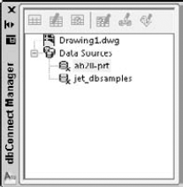
You can dock and undock the dbConnect Manager like any palette. You can also resize it by dragging its right border left or right. After you open the dbConnect Manager, you see a list of open drawings and configured data sources.
Follow these steps to connect an external database to a drawing:
Open the drawing that you want to connect with a database.
At the command line, type dbconnect
Right-click the data source to which you want to connect. (The names listed come from the names that you entered when you configured the data source in AutoCAD.) Choose Connect.
AutoCAD lists the database tables associated with the data source. The entire database structure is now connected, and you can view and work with the database data within AutoCAD. In order to do the following exercise, you must have completed the previous two exercises.
STEPS: Connecting a Database to a Drawing
You should have
ab20-01.dwgopen from the previous exercise.At the command line, type dbconnect
Right-click
ab20-prtand choose Connect. The dbConnect Manager lists the database tablePART NO.Save the drawing. Keep it open. Continue to the next exercise.
After your database is connected, you choose the database table with which you want to work. If necessary, click the plus sign next to the desired database to see the actual database files that are available. The database file also displays a plus sign. If necessary, click it to display the database tables within the database file. (A database file can contain more than one table.)
You can view or edit a table in the Data View window:
View the data when you have no need to edit it. To view your data, right-click the table that you want to view and choose View Table.
Edit the data when you need to make changes to your database from within AutoCAD. To edit your data, right-click and choose Edit Table.
To view or edit a table, select the table. Choose View Table or Edit Table from the dbConnect Manager's toolbar. You can also right-click the table and choose View Table or Edit Table from the shortcut menu.
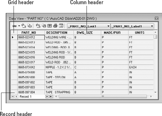
Figure 20.5 shows the Data View window when you choose Edit Table. (When you choose View Table, you see the same view but the data cells are gray.)
The Data View window presents your data in a grid, with each piece of data in a cell, like a spreadsheet. You can use the scroll bars to scroll through the data. To the left of the horizontal scroll bar, you can use the arrows to move from record to record. The far left and right arrows with a vertical bar move you to the first and last records, respectively.
You can temporarily change the way the data is displayed. These changes are discarded after you close the Data View window; they don't affect the data file in your database. Here are your options:
Resize a column. You may find that your data doesn't completely display in a column or that columns don't all appear in the window. Click the grid line to the right of any column header and drag it to the left or right. You can also resize the entire Data View window by dragging on its sides or bottom.
Move a column. You can change the order of the columns by moving a column to another location. Click the column's header to select the column. Then click and drag the column to the location you want. A black vertical line indicates where the column will land.
Hide a column. You can hide a column with which you don't need to work. This is especially helpful if you have many columns and can't fit them easily on the screen. Click the column's header to select the column. Then right-click the column header and choose Hide. To re-display the column, right-click any column header and choose Unhide All.
Sort records. You can sort records in ascending (low to high) or descending (high to low) order. Sorting helps you to more easily find the records that you want. Right-click any column header and choose Sort to open the Sort dialog box. In the Sort By drop-down list, choose the column that you want to sort by first. Then choose Ascending or Descending. This column may have duplicate records. If so, you may want to choose a secondary column for sorting in the Then By drop-down list. Choose Ascending or Descending for the secondary column. AutoCAD will then sort first by the first column and then by the second column. You can choose up to five columns to sort by.
Freeze one or more columns. Freezing one or more contiguous columns moves them to the left column. Select the columns by clicking their column headers. (Press Ctrl to select additional columns. You can also select one column, press Shift, and select another column to select all the columns in between.) Then right-click a selected column and choose Freeze. To return the column to its original location, right-click and choose Unfreeze All.
Align text. You can align text in a column or columns. By default, columns use the Standard alignment, which right-aligns numbers and left-aligns everything else. Select a column or columns by clicking the column header(s), right-click any column header, and choose Align. Then choose Standard, Left, Center, or Right.
Format text. You can format the font, font style, font size, effects (strikethrough and underline), and color of the text in the Data View window. Note that, unlike the other changes previously listed, these changes continue to affect the formatting of the Data View window the next time you open a Data View window. Right-click the upper-left corner of the data grid and choose Format to open the Format dialog box. Choose the formatting that you want and then click OK.
Tip
To get the Data View window out of the way, you can dock it. Right-click in the Data View window's toolbar area and choose Allow Docking. Then drag the window to the right edge of your screen (assuming your dbConnect window is on the left side of your screen). You can also choose to anchor the dbConnect window on the left or right by choosing Anchor Left or Anchor Right.
Although you can scroll through your data's records, if you have many records, this can be time-consuming. You can search for a particular record by specifying a desired value. Follow these steps:
Select any cell in the column that contains the record that you want to find. If you want to search the entire column, choose the first or last cell in the column.
In the Data View, right-click over a cell and choose Find to open the Find dialog box.
In the Find What text box, type a value (text, numbers, or a combination). Choose to search either Up (from the selected cell to the first record) or Down (from the selected cell to the last record). If desired, choose Match Case. Then click Find Next to find the next instance of the value. Continue to click Find Next to move to the next matching record.
Tip
If you want, you can copy your formatting, including sorting, to the Clipboard and paste it into your DBMS. To do this, select the records that you want to export. To export the entire database, click the grid header. Then right-click any cell and choose Copy. Open your DBMS and click Paste from the Standard toolbar.
In the following exercise, you practice using the Data View window.
STEPS: Working with the Data View Window
Ab20-01.dwgshould still be open from the previous exercise. If there's a plus sign next toab20-prt, click it to display the"PART NO"table.Right-click the table icon and choose Edit Table. The Data View window opens.
Right-click the grid header (in the upper-left corner of the grid) and choose Format. In the Format dialog box, choose Arial as the font and 10 as the font size. Click OK.
The columns are too wide and you can't see all of them. Click the grid line to the right of the PART_NO column and drag it to the left so that the width of the column just fits the width of the part numbers. Do the same with the other columns. (You can also double-click the grid line between columns to automatically resize the column to the left to the widest value.) To access the right grid line of the last column (UNITS), expand the right side of the entire window. Then resize the UNITS column and shrink the Data View window to fit.
Right-click the PART_NO column's header and choose Align
To practice moving around the table, click the rightmost arrow at the bottom of the Data View window (to the left of the horizontal scroll bar) to move to the last record. Use the vertical scroll bar to scroll through the database and get an idea of its contents. Click any cell. Click a row header to select an entire row. Click a column header to select an entire column.
To sort the records by description and help you to find all the angles, right-click the DESCRIPTION column header and choose Sort. In the Sort dialog box, choose DESCRIPTION from the Sort By drop-down list, and then click Ascending (if it's not already selected). Because there are a number of duplicate records in the DESCRIPTION column, choose PART_NO in the Then By drop-down list, which should also be sorted in ascending order. Click OK. AutoCAD sorts the data by description, and then by part number.
Say that you want to find part number 9003-242-001. Right-click the top cell in the PART_NO column. Choose Find. In the Find dialog box, type 9003-242-001 and choose Down in the Direction section. Click Find Next. AutoCAD highlights the cell containing that part number.
Close the Find dialog box and save your drawing. Keep it open for the next exercise.
After you open your data in Edit mode, you can easily edit the data. You can change the value of any record. You can add or delete records to reflect new or deleted objects in your drawing. Changing a record is as simple as selecting a cell and typing a new value.
To add a new record, right-click any record (row) header and choose Add New Record. AutoCAD opens up a space for a new record at the end of the list of records. Type the data for the new record, tabbing from column to column. (You can also use the right-arrow key to move to the next column.)
To delete a record, right-click the record header of the record that you want to delete, selecting the entire record. Choose Delete Record. You need to confirm the deletion in the dialog box that pops up.
Warning
You should not use the DBMS to edit a database separately while it is connected to AutoCAD. If you do edit the database table outside of AutoCAD during an AutoCAD connection, you may get system crashes or corrupted data. If you need to edit the database by using the DBMS, make sure that you disconnect the table first in the dbConnect Manager palette.
AutoCAD doesn't save your changes until you commit them. To save your changes, right-click the grid header — the cell at the top-left corner of the Data View window — and choose Commit. To discard your changes, choose Restore, which restores the original values of the database when you opened the Data View window.
STEPS: Editing Data
With
ab20-01.dwgand the Data View window still open from the preceding exercise, the part number that you found in the previous exercise (9003-242-001) should still be highlighted. If not, find it following the instructions in Step 8 of the preceding exercise.Note that the MADE/PUR column indicates that this horizontal angle is purchased. Say that the company has decided to make this angle. Click the P in the MADE/PUR column of the 9003-242-001 record and type M.
To add a record, right-click any record (row) header and choose Add New Record. AutoCAD moves you to the end of the records with a space for a new record. Type the following, tabbing between each column:
8665-023-018 WELDING ROD - .05 DIA S.S. B P FT
I don't recommend saving the changes to the database because you may want to do this exercise again in the future. Right-click the grid header (in the upper-left corner of the grid) and choose Restore. AutoCAD closes the Data View window.
Keep the drawing open for the next exercise.
The main purpose of using data connectivity is to link data to objects in your drawing. A row of data contains information about the real-life object that objects in your drawing represent. By connecting a row of data to an object or objects in your drawing, you can do the following:
View information, such as price, source, next service date, and so on, about the real-life object while in your drawing.
Update a drawing based on changes in the database, or vice versa, to keep your drawings and your database synchronized.
Display a label containing data information next to a drawing object.
When AutoCAD creates a link, it associates an object or objects with a row in your database. To do so, AutoCAD needs to know which field (column) to look in to identify the row. For example, let's say you want to link price information to some objects. However, several rows may contain the same price information. If you provide a field that contains no duplicate data, AutoCAD can always locate the required row. If AutoCAD finds two rows with the same data, it accesses the first row. It makes sense, therefore, to be careful to choose a column that contains no duplicate values. If your data doesn't contain such a column, most DBMSs can create an index field that ensures that each row is unique.
A link template identifies which fields are associated with a link between the data and a drawing object. A link template also identifies your database. After you create a link template, you can open your data directly from the template, which is listed in the dbConnect window.
If you want to associate data from more than one database table to a single object, you may need to create more than one link template for an object.
To create a link template, follow these steps:

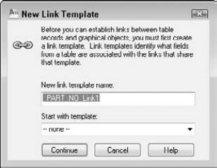
In the New Link Template Name text box of the New Link Template dialog box, shown in Figure 20.6, type a name for the link template. AutoCAD assigns an automatic name, using the name of the data source and Link1, Link2, and so on. You can use that name or type your own. If you have a previous link template that you want to use as a basis for the new template, choose it from the Start with Template drop-down list. Click Continue.
In the Link Template dialog box, check a key field. If the key field that you choose contains any duplicate rows, you should choose a second key field.
Click OK. AutoCAD creates the link template, which is added to the dbConnect Manager palette beneath the current drawing.
You're now ready to link data with drawing objects.
If the structure of your database changes dramatically, you may need to edit a link template. For example, a field that contained no duplicate entries might now contain some. Other changes requiring a change in the template would be a change in the name or length of a field. To edit a link template:
Connect to the desired database table.
On the dbConnect Manager, right-click over a link template and choose Edit (the DBCEDITLT command). If you use the DBCEDITLT command, the Select a Database Object dialog box opens. From the Select a Database Object dialog box, choose a link template and click Continue.
Check one (or more) of the key fields and click OK.
You can delete a link template by right-clicking over the link template and choosing Delete. You can also rename or duplicate a link template by right-clicking the link template and choosing Rename or Duplicate.
This exercise requires that you have completed the previous exercises in this chapter.
STEPS: Creating a Link Template
Continue with
ab20-01.dwgfrom the previous exercise. In the dbConnect window, right-click"PART NO"and choose Edit Table to open the Data View window.Choose New Link Template from the dbConnect Manager's toolbar. If necessary, select the PART_NO table and click Continue.
In the New Link Template dialog box, use AutoCAD's suggested name, _PART_NO_Link1. Click Continue.
In the Link Template dialog box, check PART_NO. This column contains no duplicate rows.
Click OK to return to the drawing. You see the new link template with a chain-link icon in the dbConnect Manager palette just under the name of the open drawing.
Save your drawing. Leave it open to continue with the next exercise.
You're now ready to link drawing objects to your database.
You can link a drawing object to as many records in a database as you want, and you can link one database record to several drawing objects. For example, you may want to link a record containing part-number information to the part in the drawing. However, that part may be made up of a number of objects, such as lines, arcs, and circles. You can link the record to all those objects in your drawing that make up the part. On the other hand, if you have a database of office equipment, you may attach a row representing telephone numbers and telephones to an object in your drawing representing a phone. However, if someone has a two-line phone, you may need to attach two rows to that one telephone object in your drawing.
Here's how to create a link:
Open a Data View window that has a defined link template and choose a link template from the Select a Link Template drop-down list at the top of the window.
Select one or more records that you want to link to your drawing.
Click the down arrow next to Link and Label Settings on the Data View's toolbar, and choose Create Links.

AutoCAD returns you to your drawing. Select one or more objects and press Enter to end object selection.
AutoCAD provides a message on the command line, for example: 1 Record(s) linked with 1 Object(s). You now have a link between your data and your drawing.
Warning
If you create a link between a drawing object and a row and in a later session of AutoCAD edit that object without connecting to the database table, the link information may become corrupted.
You can delete a link by selecting a linked object and right-clicking in the drawing area. From the shortcut menu, choose Links
After you create a link, you need to be able to see which rows are linked to which objects before you can make decisions regarding either the data or the drawing objects. You can view the link from either side. That is, you can select an object and see which row or rows it is linked to or you can select a row and have AutoCAD select the object or objects to which it's linked. In both cases, you need to have a Data View table displayed.

Note
To restore the full data in the Data View window, close the Data View window and then re-open it from the dbConnect Manager palette.

You'll find that the Data View window obscures your drawing. You can drag it to the bottom of your screen, resize it, or dock it.
Tip
When you use View Linked Objects, the selected objects form a selection set. You can then use the results with other commands that allow prior selection of objects. For commands that you must execute before selecting objects, type p
If you want to move from object to object or row to row to view your links one after another, try Auto-View. The AutoView feature automatically highlights either objects, when you choose a row in the Data View window, or rows, when you choose objects in your drawing. However, you can work from only one side of the equation — either rows or objects — at a time. Here's how it works:
When you're in Auto-View, you can't select records. If you click another record's row header to create a link, AutoCAD just tells you 0 Object(s) found matching 0 selected Record(s). Be sure to turn off Auto-View when you go on to another task.
After you create links in your drawing, you need to be careful how you edit your database from within AutoCAD. For example, you don't want to inadvertently delete a record that is linked to an object.
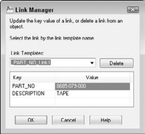
You may need to edit the key value assigned to a linked object. For example, your company may change the part-numbering scheme or you may have simply assigned the wrong part number to an object. The Link Manager enables you to edit key values for linked objects. Follow these steps:
AutoCAD updates the link.
You can also click the Delete button to delete the object's link.
You can export a list of links and the handle of the associated links' objects. A handle is a unique name that AutoCAD gives to each object in the drawing. (To view an object's handle, at the command line, type list
Follow these steps to export links:
Select a linked object, right-click in the drawing area, and choose Link
Tip
You can select the entire drawing (type all
In the Include Fields section of the Export Links dialog box, select the fields that you want to include.
In the Save In drop-down list, navigate to the folder where you want to save the file.
In the Save as Type drop-down list, choose one of the three options: comma-delimited format, space-delimited format, or native database format.
Click Save.
AutoCAD creates the file.
You can use this file to create a schedule of objects with links — but it takes some work. The comma-delimited format seems to work better than the space-delimited format. You'll probably want to edit the file first to remove the object handles. You can open the Multiline In-Place Text Editor and click Import Text to import the output file into your drawing. You can also open the output file, copy it to the Clipboard, and paste it into your drawing. The Import Text method enables you to format the text as you would any multiline text but takes some experimenting to set up in the proper columns. You can also import the file into a spreadsheet and format it before importing it into your drawing. If you used the native format, you can open it in your DBMS, format it, and import it into your drawing. (See Chapter 27 for more information on importing files.)
STEPS: Creating and Viewing Links
You should have
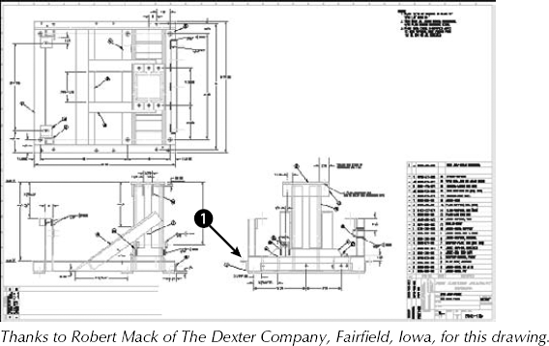
ab20-01.dwgopen from the previous exercise. The Data View window is open with the database visible. The _PART_NO_Link1 link template is current. You can see the entire drawing in Figure 20.8.To locate the record that you need, in the Data View window click the leftmost arrow next to the horizontal scroll bar to move to the first record. Right-click in the PART_NO column of the Data View window and choose Find. In the Find dialog box, type 9003-242-001. The direction should be down. Click Find Next. AutoCAD finds the record. Close the Find dialog box by clicking its Cancel button.
Click the row's header (the arrow to the left of the row) to select the entire row.

Click Link! on the Data View's toolbar.
AutoCAD returns you to your drawing. Use a Zoom window to zoom into the area marked

Select all the objects that make up the angle bracket indicated by


Save your drawing and keep it open for the next exercise.
A label is multiline text that appears in your drawing, displaying data from a row in your database. You can choose which fields from the row are displayed. There are two types of labels:
Attached labels are attached to objects and are displayed with a leader pointing to the object. If you move the object, the label moves as well. Use an attached label when the row in the database applies to one or more specific objects in your drawing.
Freestanding labels are independent of any object. You would use freestanding labels when your database applies to the drawing as a whole.
Before creating a label, you need to create a label template. A label template specifies which fields will be included in the label, as well as text formatting. Here's how to create a label template:
On the dbConnect Manager, select a table or link template, and click New Label Template on the dbConnect Manager's toolbar.
In the New Label Template dialog box, type a template name in the New Label Template Name text box. AutoCAD suggests a default name. If you have an existing label template that you would like to use as a basis for the new label template, choose it from the Start with Template drop-down list. Click Continue.
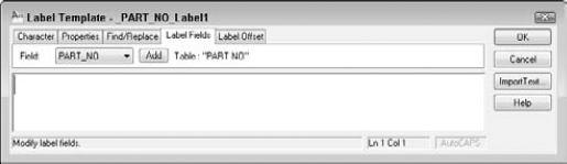
AutoCAD opens the Label Template dialog box, shown in Figure 20.10, with the Label Fields tab displayed. Use the Character and Properties tabs to format the text.
On the Label Fields tab, choose a field that you want to appear on the label from the Field drop-down list. Then click Add. Continue to add fields as desired. You can add text to this field. For example, you could type Part No: before the
PART_NOfield.Note
If you add text before or after the field, don't forget to add a space between the text and the field so that the result is Part No: 9003-242-001 rather than Part No:9003-242-001, for example.
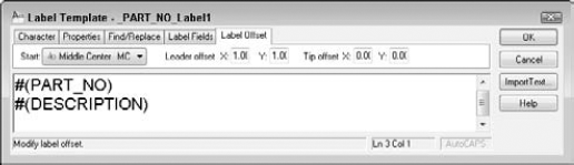
Click the Label Offset tab, as shown in Figure 20.11. This tab defines the placement of the label and the leader that connects the label with the object. In the Start drop-down list, choose a justification. This defines where on the object AutoCAD places the tip of the leader.
In the Leader Offset text boxes, type an X and Y offset (in units). This offset represents the X and Y distances between the point of the leader arrow and the insertion point of the text. (If this distance is too small to fit an arrow, the arrow is suppressed.)
In the Tip Offset text boxes, type an X and Y offset (in units). This offset represents the distance between the point of the leader arrow and the object to which it points. By default, this is set to 0,0 so that the point of the leader arrow touches its object.
Click OK to close the Label Template dialog box and place the label.
After you create the label template, you can create attached and free-standing labels. The settings on the Label Offset tab apply only to attached labels.
You can edit a label template to change the included fields or the formatting. To edit a label template, right-click the label template on the dbConnect Manager and choose Edit. Use the Label Template dialog box to edit the label template by using the same steps that you used to create it. Click OK after you're done.
You create a link between a row and an object and an associated attached label at the same time. You need to have a table open and to have defined both a link and a label template. If you have defined more than one link or label template, choose the desired template(s) from the drop-down list at the top of the Data View window. Follow these steps:
Select the record that you want to link by clicking its row header in the Data View window.
Click the down arrow next to Link and Label Settings on the Data View's toolbar, and choose Create Attached Labels. This puts you in Creating Attached Labels mode, which means that from now on any links that you create also create labels.
Click Create Attached Labels on the Data View's toolbar.
At the
Select objects:prompt, choose the object(s) that you want to attach to the label. End object selection.AutoCAD automatically places the label based on the label template. If you selected more than one object, labels are placed on all the objects (which can get confusing).
Of course, you can then move the labels and leaders to a more suitable location.
If you've already created a link to an object, follow the same procedure. The link is re-created along with the attached label.
To create a free-standing label, you need to have a table open with at least a link and a label template. If you have more than one template defined, choose the one that you want to use in the drop-down list at the top of the Data View window. Follow these steps:
Select the record that you want to link to the free-standing label.
Click the down arrow next to Link and Label Settings on the Data View's toolbar, and choose Create Freestanding Labels.
Click Create Freestanding Labels on the Data View's toolbar.
At the
Specify point for label:prompt, pick a point in your drawing. AutoCAD places the free-standing label and displays this message on the command line:1 Record(s) linked with 1 Label(s).
When you create a free-standing label, the row and the label are linked. If you select a row linked to a free-standing label and click View Linked Objects in Drawing on the Data View's toolbar, AutoCAD selects the label.
If the data in the database is changed from within the DBMS, the labels in your drawing may become outdated. To ensure that your labels are always accurate, you should periodically update them. To update labels, on the dbConnect Manager, right-click the current drawing file and choose Reload Labels (or right-click a label template and choose Reload).
STEPS: Creating a Label Template and a Label
Continue with
ab20-01.dwgfrom the previous exercise. The Data View window should still be open. Press Esc to make sure that no objects are still selected.On the dbConnect Manager, select a table or link template, and click New Label Template on the dbConnect Manager's toolbar.
In the New Label Template dialog box, click Continue to use the default name.
In the Label Template dialog box, click the Label Fields tab. Choose PART_NO from the Field drop-down list. Click Add.
Choose DESCRIPTION from the Field drop-down list and then click Add.
Click the Label Offset tab. In the Start drop-down list, choose Top Left. Set the Leader offset X and Y values to 2.
Click the Character tab. Select all the text and change the height to

Click OK.
Click the down arrow next to Link and Label Settings on the Data View's toolbar, and choose Create Attached Labels.
Click Create Attached Labels on the Data View's toolbar.
At the
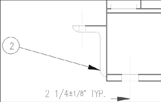
Select objects:prompt, choose the horizontal line marked at the top of the angle that you linked in the previous exercise. Press Enter to end object selection. AutoCAD automatically places the label.The label covers existing objects. Pick the text of the label and then click its grip. Move the text to the left and pick a better location. The leader automatically changes direction and ends at the left side.
Save your drawing. Leave it open for the next exercise.
You can use SQL (Structured Query Language) statements to gather more information about the elements in the drawing and database files. SQL is the language used by almost all database-management systems for refining the information that you get from a database.
AutoCAD uses the Query Editor to enable you to design queries. For example, you can do the following:
Query the contents of a database to view a specified subset of the data.
View a subset of records that falls into a certain range of values.
Access all the tables in one data source with a series of SQL commands.
In addition, the Link Select dialog box enables you to create a selection set of objects by combining SQL queries and direct selection of objects in your drawing.
To open the Query Editor, follow these steps:

In the New Query dialog box, type a name for the new query or accept the name that AutoCAD supplies. To base a query on an existing query, choose an existing query from the drop-down list. Click Continue.
AutoCAD opens the Query Editor, as shown in Figure 20.12. The Query Editor is designed to provide something for everyone — whether you're just starting out or you're an expert at SQL.
To restore the original view in the Data View window after a query, do one of the following:
Close the Data View window and then re-open it from the dbConnect window.
Click the Query Builder tab and right-click any used cell. Choose Clear Grid. Click Yes at the warning message. Then click Execute.
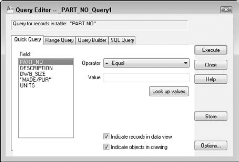
Figure 20.12. The Query Editor's four tabs enable you to build queries to refine how you view your database.
Use the Quick Query tab to create simple queries based on one field, an operator, and a single value. For example, you can create a query that finds all records from the current table where the field DWG_SIZE equals E. You can also find all records where DWG_SIZE does not equal E.
From the Field box, choose a field. In the Operator drop-down list, choose an operator, such as equal (=) or greater than (>). In the Value box, type a value for the field. If you're not sure what values are available, click Look Up Values. (This can be slow in a large database or when you're working with a database across a busy network.)
Warning
Queries are case-sensitive. A value of "B" is not the same as "b." You need to be aware of the case used in your database. Some databases are all uppercase, making it easy to specify values. Just turn on Caps Lock and type away.
Choose Indicate Records in Data View and/or Indicate Objects in Drawing. By default, both are checked. To save the query for future use, click Store. Click Execute to see the results. To return to the Query Editor, choose Return to Query on the Data View window toolbar. Table 20.2 lists the available operators.
Table 20.2. Query Operators
Operator | Description |
|---|---|
Equal (=) | Records that match the value exactly. |
Not equal (<>) | All records except those that match the value exactly. |
Greater than (>) | Records greater than the value. Includes text. For example, |
Less than (<) | Records less than the value. |
Greater than or equal (>=) | Records that are greater than or match the value exactly. |
Less than or equal (<=) | Records that are less than or match the value exactly. |
Like | Records that contain the value. You must use the |
In | Records that match the values that you specify. You list the values, separated by a comma. For example, you could find records for which the field |
Is null | Records that have no value. The Value box is unavailable. You can use this to find missing data. |
Is not null | Records that have a value. You can use this to remove from view all records with missing data. |
The Range Query tab finds records based on one field and a range of values. For example, you can find all records where the field DWG_SIZE ranges from B to D. The range can be either textual or numeric.
To construct a range query, choose a field from the Fields list. Then type the beginning value of the range in the From box and the ending value of the range in the Through box. In both cases, you can click Look Up Values to choose from a list of available values.
Click Store to save the query. Click Execute to execute the query.
The Query Builder enables you to create multiple criteria. For example, you can create a query that finds records where the field DWG_SIZE ranges from B to D and the field PART_NO is greater than 9029-072-001. In order to build the criteria, you use Boolean operators and parenthetical grouping. This tab also enables you to specify which fields will appear in the Data View window and to sort the records. Using all these options offers a great deal of flexibility to create a complex query without knowing SQL. Here's how it works:
Andoperator. Displays the records that meet both the criteria before and after theAndoperator.Oroperator. Displays records that meet either of the criteria before and after theOroperator.Parenthetical grouping. Enables you to group sets of criteria. For example, you can group one set of two criteria that use an
Andoperator and a second set of two criteria that use anAndoperator. Then you can put anOroperator between the two groups sets.
To create a query using multiple criteria, follow these steps:
On the first line, choose a field from the Field column. (When you click the first cell in the Field column, a drop-down arrow appears.)
Choose an operator from the Operator column.
Type a value in the Value cell. (An ellipsis button appears, and you can choose from all the values in the database.)
Click in the Logical cell to insert the
Andoperator. Clicking again changes the operator toOr.Move to the second line and create the next row of criteria. Continue until you've specified all the criteria that you want.
Add parenthetical grouping. Click to the left of the Field column of a row to insert a left parenthesis and between the Value and Logical columns to insert a right parenthesis. Continue to insert all the parentheses that you need. You can't insert parentheses until you have enough rows defined for a parenthesis to make sense.
Click Store to save the query. Click Execute to execute the Query.
You can also limit which fields appear in the Data View table. First define the query in the top half of the tab. The query does not need to be complex. Then select the first field from the Fields in Table list. Click Add above the Show Fields list. Continue until you have all the fields that you want. To start from scratch, right-click in the Show Fields list and choose Clear All. To remove one field, right-click it and choose Clear Field Name.
To sort the data, choose the first field that you want to sort by from the Show Fields list. (You can only sort by fields that you're showing.) Click Add above the Sort By list. By default, AutoCAD sorts by ascending order. To sort by descending order, click the Ascending/Descending button. You can click it again to change the order back to ascending. You can also repeat the process for additional fields.
Click Store to save the query. Click Execute to execute the Query.
Here's where the fun is. Try creating a query in one of the first three tabs and then click the SQL Query tab. Lo and behold, there is your query in SQL language. This is a great way to learn SQL.
The SQL Query tab is the only tab you can use to create a query to search more than one database table. Choose a table in the Table section and click Add. You can build the query by specifying fields, an operator, and values. As you work, you see the results in the top box, in SQL language.
The Check button enables you to check the SQL query before executing it. Click Store to save the query. Click Execute to execute the Query.
Although complete coverage of SQL syntax is beyond the scope of this book, you may find a few rules helpful:
Text data must be enclosed in single quotation marks ('B').
Column names are not case-sensitive, but column values are.
There are certain SQL keywords that are used in the program. You cannot use these as table or column names. Examples include CHAR, GROUP, SQL, TABLE, USER, and CURRENT.
In most standard SQL syntax, you need to end each statement with a semicolon (;). However, this is not necessary in AutoCAD.
You cannot use AutoCAD or DOS wildcard characters such as ? or * in column values or names.
To name more than one specification, separate each one with a comma.
The SELECT statement is probably the most common SQL statement. The SELECT statement can retrieve a subset of the rows in one or more tables, retrieve a subset of the columns in one or more tables, or link rows in two or more tables to retrieve common data to both tables.
The following shows the syntax of the SQL SELECT statement, including modifying statements that instruct the DBMS exactly which rows to select:
SELECT <select list>
FROM <table name> [{,<table name>}...]
[WHERE <search condition>]
[GROUP BY <column spec>[{,<column spec>}...]
[HAVING <search condition>]
[ORDER BY <sort spec> [{,<sort spec>}...]
In the preceding syntax, square brackets ([]) indicate optional elements, an ellipsis (...) indicates that the statement may be repeated, and curly brackets ({}) mean that the elements are listed in sequence.
Here is the meaning of the statement functions:
The SELECT statement specifies the columns to retrieve.
The FROM clause specifies the tables containing the specified columns.
The WHERE clause specifies the rows that you want to retrieve in the tables.
The GROUP BY clause divides a table into groups. Groups are designated by a column name or by the results of computed numeric data type columns.
The ORDER BY clause sorts results into one or more columns in either ascending (ASC) or descending (DESC) order.
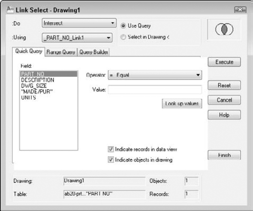
Link Select enables you to create combined selection sets of objects. You can define the selection sets either by using the Query Editor or by selecting objects directly in your drawing, or you can use a combination of these two methods. You first define a selection set called A. Then you define a selection set called B. Then you combine the two selection sets by using logical operators.
You need to have your links already set up so that AutoCAD knows the relationship between your records and objects in the drawing.
As you work, the status area at the bottom of the dialog box displays the results of the running Link Select operation, both in terms of the number of linked objects and the number of records that currently meet your specifications.
Table 20.3 shows how the logical operators work.
Table 20.3. Logical Operators for Selection Sets in Link Select
Operator | Function |
|---|---|
Union | Combines both selection sets |
Subtract A-B | Subtracts the second selection set of objects from the first |
Subtract B-A | Subtracts the first selection set of objects from the second |
Intersect | Selects only objects that are contained in both selection sets |
The Link Select dialog box contains its own version of the Query Editor so that you can build queries without leaving the dialog box.
To use Link Select, follow these steps:
On the dbConnect Manager, select a link template and right-click. Choose Link Select to open the Link Select dialog box, as shown in Figure 20.13.
At the top-center of the dialog box, choose either Use Query or Select in Drawing.
If you choose Use Query, use the Query tabs to specify a query.
If you choose Select in Drawing, click Select (the Execute button changes to the Select button) to return to your drawing and choose objects in the drawing at the
Select objects:prompt. End object selection to return to the Link Select dialog box.
Click Execute to add the query or selection of objects in your drawing to the Link Select operation.
Create a second selection set by using the same process.
From the Do drop-down list, choose one of the logical operators. You now have one selection set from the combined selection sets that you specified.
If you want, you can now create an additional selection set and use an operator to combine it with the previous selection set created in Step 5.
If you use queries a lot, you want to keep track of them. You can store, edit, rename, and delete queries. You can also import and export them for use by others. You do this by saving the information in a query file.
As I discussed previously, you can store a query by clicking Store on any tab. Stored queries are displayed under the drawing in the dbConnect Manager. To execute a stored query, on the dbConnect Manager, right-click over a stored query and choose Execute. It helps if the queries have names that relate meaningfully to the query.
You can edit stored queries by right-clicking over a stored query in the dbConnect Manager and choosing Edit. In the Query Editor, make the desired changes and choose Store.
To rename a query, click it in the dbConnect Manager. Click it again to display an edit box. You can now edit the query's name. Remember that you have to name the query upfront. If you're not sure what the query will consist of, use the default name, construct your query, and then rename it to something more meaningful afterward.
To delete a query, right-click over a stored query in the dbConnect Manager and choose Delete.
To export a query that has been saved (by clicking Store in the Query Editor), right-click the drawing that contains stored queries in the dbConnect Manager and choose Export Query Set. In the Export Query Set dialog box, navigate to the desired folder and choose a name. Click Save. Queries have a DBQ filename extension.
Note
To find the location of your queries, choose Application Menu
To import a query that has been exported and named, right-click over the drawing that you want to import queries into in the dbConnect Manager and choose Import Query Set. You need to know the name and location of the .dbq file. In the Import Query Set dialog box, locate the file and click Open. AutoCAD assigns default names to queries.
Using external databases to store data about drawing objects can reduce the size of drawings, simplify reporting, make data accessible to all users on a network, and enable you to edit a database from inside AutoCAD. In this chapter you read about:
Configuring a data source
Connecting a database table with your drawing
Creating a link template
Creating links between drawing objects and rows in the database
Creating labels containing information from the database
Defining SQL queries to select and sort the data that you view
Selecting objects based on queries
Storing and saving queries
This chapter ends Part III, "Working with Data." In Part IV, you start to draw in three dimensions. In the next chapter, I discuss how to specify 3D coordinates.