
No drawing project is ever completed without changes. You make changes in a drawing for many reasons. Some editing processes are simply part of the drawing process, such as copying an object rather than drawing it a second time from scratch. Other types of editing involve making changes to many objects at once, such as moving an entire section of a drawing to make room for additional objects. You often also need to erase, move, rotate, and resize objects.
Making changes to a drawing is called editing. In order to edit an object, you need to select it. AutoCAD and AutoCAD LT offer numerous techniques for selecting objects. In this chapter, I cover basic editing commands as well as most of the ways to select objects. The rest of the 2D editing commands, as well as additional selection and editing methods — grips, the Properties palette, selection filters, and groups — are covered in the next chapter.
Most of the editing commands are on the Home tab in the Modify panel. In most cases, you can do either one of the following:
Start the command first and then select the objects to which the command applies.
Select the objects first and then start the command.
The question of which comes first, the command or the object, is fully covered later in this chapter.
Note
Although you can use the editing tools that I describe in this chapter in a 3D environment, this chapter assumes that you are working in a 2D environment. (AutoCAD LT doesn't offer a 3D environment.) To make sure that you're in a 2D environment, set the workspace to AutoCAD Classic or 2D Drafting & Annotation (choose it from the Workspace Switching pop-up list on the status bar) and set the visual style to 2D Wireframe (use the 2D Wireframe option of the vscurrent command). If you still see the Z axis on the UCS icon, choose View tab
When you start to edit drawings, it is important to first learn how to select objects. The simplest selection technique is to place the pickbox — the box at the intersection of the crosshairs — over the object and click with the pick button on the mouse. This is known as picking an object. By default, when you select an object, the Quick Properties panel appears. I discuss this panel in Chapters 10 and 12.
When you pass the cursor over an object before choosing any editing command, the object becomes thicker and dashed. This rollover highlighting helps you to know which object you will select when you click. This feature is helpful in a busy drawing with many objects close together or overlapping. I explain how to fine-tune the effect in the next chapter. You also see a rollover tooltip that displays some basic properties of the object.
If you start an editing command before selecting an object, the command responds with the Select objects: prompt. When you then pick an object to select it, AutoCAD or AutoCAD LT highlights it, usually by making the object dashed, as shown on the left side of Figure 9.1.
The command continues to provide Select objects: prompts so that you can select other objects. Continue to select objects until you have selected all the objects that you want to edit. Then press Enter to end the Select objects: prompt.
When you select an object before choosing an editing command, the lines of the selected object become dashed and you also see one or more small boxes, called grips, as shown on the right side of Figure 9.1. Chapter 10 covers grips. In the next few exercises, you use this picking technique to select objects. Other selection methods are covered later in this chapter.
Note
The PURGE command erases two kinds of undesirable objects that sometimes mistakenly exist in a drawing — zero-length lines and empty text objects. I cover the PURGE command more in Chapter 11.
Note
The drawing used in the following exercise on picking and erasing objects, ab09-a.dwg, is in the Drawings folder on the DVD.
STEPS: Picking and Erasing Objects
Open
ab09-a.dwgfrom the DVD.Save the file as
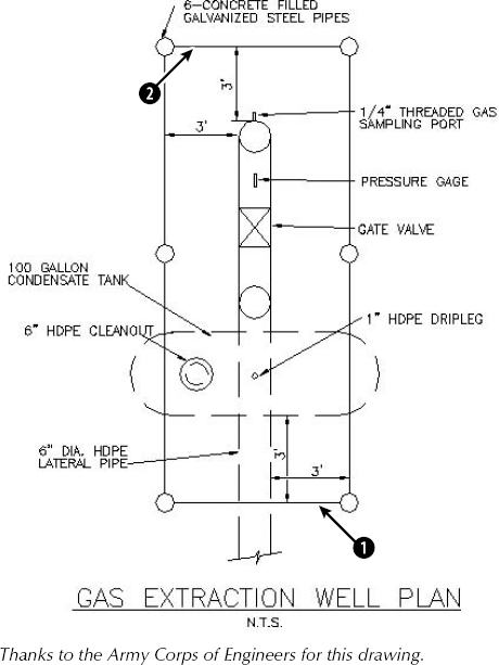
ab09-01.dwgin yourAutoCAD Biblefolder. This drawing is a schematic of a gas extraction well, as shown in Figure 9.2.To erase the line at point


Right-click and choose Repeat Erase.
At the
Select objects:prompt, pick the line at point
The command responds with
1 foundand repeats theSelect objects:prompt. Right-click to end theSelect objects:prompt. The line is erased.Save your drawing.
Note
The OOPS command restores the most recently erased object and is covered in Chapter 18.
Use the MOVE command to move objects in your drawing. You need to specify the distance and direction that you want the object to move.
Specify base point or [displacement] <Displacement>:
You now have two ways of specifying how to move the object or objects:
Displacement method. At the prompt, state the entire displacement as an X,Y coordinate such as 2,3 or a polar coordinate such as 2<60. The command responds with the
Specify second point of displacement or <use first point as displacement>:prompt. Because you've already specified all the necessary information, press Enter. AutoCAD or AutoCAD LT uses the first point you indicated as the displacement (the default) and moves the object. (Because the word displacement already implies the relative distance from the object, you do not use @, even if you have Dynamic Input on and set to Absolute coordinates.)Tip
The MOVE command remembers the most recent displacement throughout a session. To move an object the same displacement as you just moved another object, press Enter at the
Specify base point or [Displacement] <Displacement>:prompt. At theSpecify displacement <2.0000, 3.0000, 0.0000>:prompt, you see in angled brackets the last displacement that you used. Press Enter to move the object using this displacement.Base point/second point method. At the
Specify base point or [Displacement] <Displacement>:prompt, pick a base point. This can be anywhere in your drawing but is usually on or near the object that you want to move. When you specify a base point, choose an object snap on the object or a nearby, related object for exact results. At theSpecify second point of displacement or <use first point as displacement>:prompt, specify the distance and angle of movement either by picking a second point on the screen or by typing a relative coordinate. (If you have Dynamic Input on, set to the default of relative coordinates, you don't need to add the @ symbol before the coordinates.)
The displacement method requires less input and is simpler when you know the exact displacement so that you can type it in. The only disadvantage is that, as soon as you type in the displacement, you sometimes see a confusing temporary drag line and copy of your object or objects. Ignore this display and press Enter. Your object or objects move as you specified. The base point/second point method works best when you want to move an object relative to another object on the screen.
You can use PolarSnap with the base point/second point method to move an object. Turn on PolarSnap and, if necessary, use the Drafting Settings dialog box to set the increment. If the polar distance is 0, you can set it to a new value. AutoCAD and AutoCAD LT use the Snap X spacing value that you specified in the Drafting Settings dialog box. At the first prompt, pick a point such as an object snap on the object. At the second prompt, drag the object in the desired direction. Use the tooltip to guide you and then click.
You can use drag-and-drop to move objects if you aren't too particular about where they end up. Here's how it works:
Pick an object.
Continue to pick as many objects as you want to move. They all show grips.
Pick any of the objects, but not on a grip. Keep the mouse button pressed until the cursor changes to an arrow with a small rectangle.
Drag the object(s) to any other location in your drawing.
For a little more control over the placement of your objects, you can use the Windows Clipboard. Pick the object(s) that you want to move. Right-click and choose Cut from the shortcut menu. Right-click a second time and choose Paste. At the prompt for an insertion point, you can pick with an object snap or by typing coordinates. However, you can't control the base point (which is 0,0) as you can with the MOVE command, because it's always the lower-left corner of the object or of a bounding box around the object.
Note
The drawing used in the following exercise on moving objects, ab09-b.dwg, is in the Drawings folder on the DVD.
STEPS: Moving Objects
Open
ab09-b.dwgfrom the DVD.Save the file as
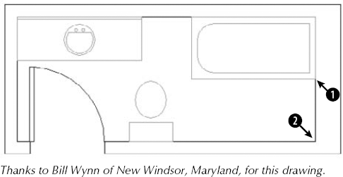
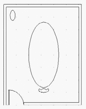
ab09-02.dwgin yourAutoCAD Biblefolder. This drawing shows the plan of a bathroom. Each object is a block, a set of objects that you can select as one object. (Chapter 18 covers blocks.) Make sure that Object Snap mode is turned on. Set a running object snap for Intersection only.
Specify base point or [Displacement] <Displacement>:
Move the cursor to the Intersection atin Figure 9.3 and click. Specify second point of displacement or <use first point as displacement>:Move the cursor to the Intersection atin Figure 9.3 and click.The tub moves to the bottom-right corner of the bathroom.
Choose Move again. Follow the prompts:
Select objects:
Pick the sink. Select objects:Specify base point or [Displacement] <Displacement>:
4'<0Specify second point of displacement or <use first point as displacement>:The sink moves 4 feet to the right.
Click Snap Mode on the status bar to turn it on. Now, right-click Snap Mode. Choose PolarSnap On (unless it is already on, in which case it is unavailable). Click Polar Tracking on the status bar.
Pick the toilet and choose Move again. At the
Specify base point or [Displacement] <Displacement>:prompt, pick the intersection at the bottom-left corner of the toilet tank. At theSpecify second point of displacement or <use first point as displacement>:prompt, move the toilet to the left until you see0'-6″<180°on the tooltip, and click. The toilet moves 6 inches to the left. (If you can't get a 180° tooltip, check your polar angle settings.)Save your drawing.
Copying is very similar to moving. In fact, the only difference is that AutoCAD or AutoCAD LT does not remove the object from its original spot, so you end up with two objects rather than one.
Specify base point or [Displacement/mOde] <Displacement>:
You now have two ways of specifying where to copy the object or objects:
Displacement method. At the
Specify base point or [Displacement/mOde] <Displacement>:prompt, state the entire displacement as an X,Y coordinate such as 2,3 or a polar coordinate such as 2<60. The command responds with theSpecify second point of displacement or <use first point as displacement>:prompt. Because you've already specified all the necessary information, press Enter. The command uses the first point that you indicated as the displacement (the default), copies the object, and ends the command. (Because the word displacement already implies the relative distance from the object, you do not use @, even if you have Dynamic Input on and set to Absolute coordinates.)Tip
The COPY command remembers the most recent displacement throughout a session. To copy an object the same displacement as you just copied any object, press Enter at the
Specify base point or [Displacement/mOde] <Displacement>:prompt. At theSpecify displacement <2.0000, 3.0000, 0.0000>:prompt, you see in angled brackets the last displacement that you used. Press Enter to copy the object using this displacement.Base point/second point method. At the
Specify base point or [Displacement/mOde] <Displacement>:prompt, pick a base point. This can be anywhere in your drawing. At theSpecify second point of displacement or <use first point as displacement>:prompt, specify the distance and angle of movement either by picking a second point on the screen or by typing in a relative coordinate. (If you have Dynamic Input on and set to the default of relative coordinates, you don't need to add the @ symbol before the coordinates.)If you use the base point/second point method, the COPY command continues to prompt you for additional copies. However, scripts and other routines use the earlier functioning, in which the command ends after creating one copy. After you make one copy, you see the
Specify second point or [Exit/Undo] <Exit>:prompt. Press Enter to use the Exit option and end the command.
Note
The COPYMODE system variable lets you specify if you want the COPY command to repeat or not. By default, as I just described, COPY repeats. Set the system variable's value to 1 to end the COPY command after one copy. You can also change how the COPY command works as you use it, with the Mode option. Choose either the Single or Multiple (the default) suboption.
If you've created more than one copy, the Undo option enables you to undo the last copy that you created. You can then continue to make more copies or end the command.
You can use PolarSnap to copy objects in the same way that you use it to move objects. For details, see the previous section. You can also use drag-and-drop to copy objects. Follow the steps in the previous section on moving objects, but press and hold the Ctrl key as you drag the object. Notice the plus sign in the cursor's rectangle. As also described in the previous section, you can use the Clipboard to copy and paste objects from one location in a drawing to another.
Note
The drawing used in the following exercise on copying objects, ab09-c.dwg, is in the Drawings folder on the DVD.
STEPS: Copying Objects
Open
ab09-c.dwgfrom the DVD.Save the file as
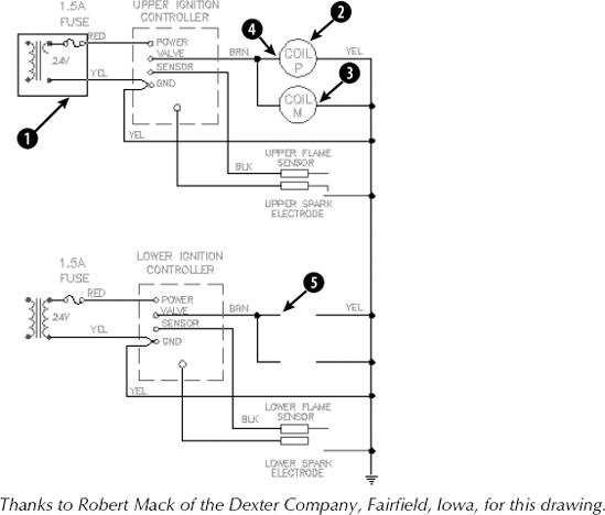
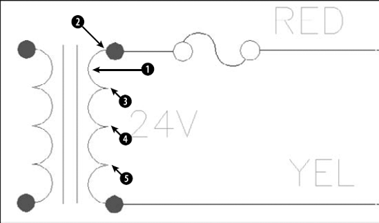
ab09-03.dwgin yourAutoCAD Biblefolder. This drawing shows part of an electrical schematic. Make sure that Object Snap is turned on. Set a running object snap for Endpoint only.Use ZOOM Window to zoom into the area of the drawing marked

Specify base point or [Displacement/mOde] <Displacement>:
Pick the endpoint at the top of the arc at(see Figure 9.5). Specify second point of displacement or <use first point as displacement>:Pick the endpoint at the bottom of the first arc at. Specify second point or [Exit/Undo] <Exit>:
Pick the endpoint at the bottom of the second arc at. Specify second point or [Exit/Undo] <Exit>:
Pick the endpoint at the bottom of the third arc at. Specify second point or [Exit/Undo] <Exit>:Use ZOOM Previous to return to your previous view.
Pick the circle at
Choose Copy again. Now select the circle at
Continuing to select objects to copy, select the circle at
At the
Specify base point or [Displacement/mOde] <Displacement>:prompt, pick the endpoint atSave your drawing.
If you use other Windows programs, you often cut, copy, and paste objects. In AutoCAD and AutoCAD LT, these commands are called CUTCLIP, COPYCLIP, and PASTECLIP. (The CLIP refers to the Windows Clipboard.) Although the MOVE and COPY commands provide more accuracy within one drawing, you can use the Clipboard to move and copy objects from one drawing to another.
You can copy objects from one drawing to another by using the drag-and-drop technique. The easiest way is to open both drawings and then choose View tab
For more control over the placement of your objects, use the Windows Clipboard. A special feature, Copy with Base Point, gives you control over the placement of your objects. Follow these steps:
Pick the object(s) that you want to copy.
Right-click and choose Copy with Base Point from the shortcut menu.
At the
Specify base point:prompt, specify a base point. An object snap is a good idea here. This action copies the object(s) to the Clipboard, including the base point.Switch to the second drawing.
Right-click in the drawing area and choose Paste. At the prompt for an insertion point, specify the insertion point by picking, using an object snap, or typing coordinates. This action pastes the object.
To copy the object(s) to the same coordinates as the original drawing, in Step 5 choose Paste to Original Coordinates from the shortcut menu. AutoCAD or AutoCAD LT pastes the object(s) in the second drawing, matching the coordinates. Depending on your drawing, you may need to ZOOM and PAN to see the copy.
You cannot specify a base point for moving (cutting) an object, but you can specify the insertion point when you paste it. The lower-left extent of the selected object(s) is the base point.
Note
You can drag objects from a drawing into another application, such as a word-processing document. For more information on working with AutoCAD or AutoCAD LT and other applications, see Chapter 27.
If your design changes or you drew at an incorrect angle, you may need to rotate one or more objects. You can easily rotate an object or objects around a base point that you specify. The base point is usually an object snap point on the object. To indicate the rotation, specify an angle of rotation. As explained in Chapter 5, by default, zero degrees is to the right, and degrees increase counterclockwise. (To change the default, choose Application Button
Tip
Use the Copy option to create a copy of the original object. After you use this option, the same prompt returns so that you can specify a rotation angle. You end up with two objects, one at the original rotation angle and one at the new rotation angle.
The most recent rotation angle that you specify becomes the default for other rotations during the same session. For example, if you rotate an object 330°, the next time you rotate an object, the prompt appears as Specify rotation angle or [Copy/Reference] <330>:. Press Enter to rotate the object using the default rotation.
The purpose of the Reference option is to let you specify an absolute rotation angle for an object. For example, let's say you want to rotate a line, whose angle you don't know, to 45°. At the Specify the reference angle <0>: prompt, you type in an angle or specify an angle by picking two points. These can be object snap points on the object that specify the object's current angle; in the example, you would use the endpoints of the line. At the Specify the new angle or [Points] <0>: prompt, type or pick a new angle or specify two points to determine the new angle. You can also pick an object snap on another object in the drawing to indicate this new angle. In the example, you would enter 45 to rotate the line to 45°. You can use the Reference option to align the object with the X or Y axis or with another object in your drawing.
Note
The drawing used in the following exercise on rotating objects, ab07-03.dwg, is in the Results folder on the DVD.
STEPS: Rotating Objects
Open
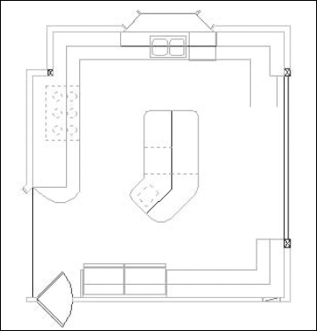
ab07-03.dwgfrom theResultsfolder of the DVD. If you did the exercise on ellipses in Chapter 7, you can open this drawing from yourAutoCAD Biblefolder.Save the file as
ab09-04.dwgin yourAutoCAD Biblefolder. This drawing shows a conference room, as shown in Figure 9.6.Set Center, Quadrant, and Perpendicular running object snaps. Object Snap mode should be on. Polar Tracking should be off.

At the
Specify base point:prompt, pick the top quadrant of the ellipse. At theSpecify rotation angle or [Copy/Reference]:prompt, type 90Click Snap Mode on the status bar to turn off snap.
To make a copy of the chair and rotate it at the same time, start the ROTATE command. At the
Select objects:prompt, pick the arc that makes the back of the chair at the bottom of the drawing. The command responds1 found. Continue to pick the two lines that make the armrests and the arc that makes the front of the chair, making sure, each time, that you see the response1 found, for a total of 4. Press Enter to end theSelect objects:prompt.To copy and rotate the selected chair, follow the prompts:
Specify base point:
Use the Center object snap to select the center of the large table. Specify rotation angle or [Copy/Reference] <90>:Right-click and choose Copy. Specify rotation angle or [Copy/Reference] <90>:180Start the COPY command and select the four objects in the new chair. Press Enter to end object selection. Follow the prompts:
Specify base point or [Displacement/mOde] <Displacement>:
Use the Center object snap to select the center of the arc that makes up the back of the chair. Specify second point of displacement or <use first point as displacement>:Pick a point about a third of the way around the right side of the conference table. Specify second point or [Exit/Undo] <Exit>:Pick a point about halfway around the right side of the conference table. Specify second point or [Exit/Undo] <Exit>:Pick a point about two-thirds of the way around the right side of the conference table. Specify second point or [Exit/Undo] <Exit>:Start the ROTATE command and select the four objects in the first of the three chairs (the top one) that you just created. Right-click to end object selection. At the
Specify base point:prompt, pick the Center object snap of either arc of the chair. At theSpecify rotation angle or [Copy/Reference]:prompt, move the cursor around, watch the image of the chair rotate, and click when the chair faces the angle of the table.Repeat Step 10 for the second chair.
Start the ROTATE command and select the four objects in the last chair that you created by using the COPY command. Follow the prompts:
Specify base point:
Choose the Center object snap of either of the chair arcs. Specify rotation angle or [Copy/Reference]:Right-click and choose Reference from the shortcut menu. Specify the reference angle <0>:Use the Quadrant object snap to pick the back arc of the chair. Specify second point:Use the Quadrant object snap to pick the front arc of the chair. Specify the new angle or [Points] <0>:Use the Perpendicular object snap to choose the conference table next to the chair.Save your drawing.
Scaling, or resizing, objects is another common editing task in AutoCAD or AutoCAD LT. As with rotating objects, you specify a base point, usually an object snap on the object. The base point is the one point on the object that does not move or change as you scale the object. The most common way to resize an object is to specify a scale factor. The current object has a scale factor of 1. Therefore, to increase the size of the object, type in a number greater than 1. For example, a scale factor of 2 doubles the size of the object. To decrease the size of the object, type in a number less than 1. A scale factor of 0.25 creates an object one quarter of its previous size. The most recent scale factor that you specify becomes the default for other scaling operations during the same session.
Use the Copy option to create a copy of the original object. After you use this option, the same prompt returns so that you can specify a scale factor. You end up with two objects, one at the original scale and one at the new scale.
As with the ROTATE command, you can scale by using the Reference option to specify an absolute length. You specify the reference length, usually the current length of the object, by typing it in or using object snaps on the object. At the Specify new length or [Points] <0'-1″> prompt, you can type a new length or pick two points. You can use the Points option to match the size of another existing object.
Note
The drawing used in the following exercise on scaling objects, ab09-d.dwg, is in the Drawings folder on the DVD.
STEPS: Scaling Objects
Open
ab09-d.dwgfrom the DVD.Save the file as
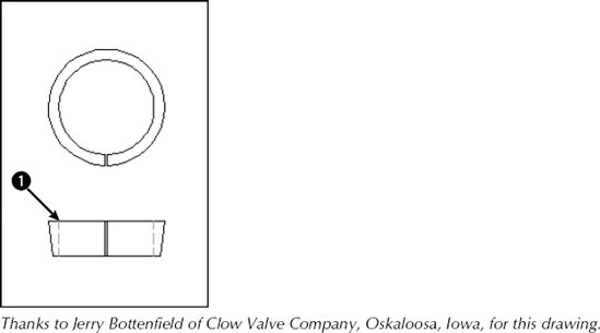
ab09-05.dwgin yourAutoCAD Biblefolder. This drawing, shown in Figure 9.7, shows part of a valve that is manufactured in several sizes. In this exercise, you scale both views to represent a different-sized valve piece. Ensure that Object Snap is on. Set running object snaps for Quadrant and Endpoint.
Specify base point:
Use the Quadrant object snap to pick the left quadrant of the inner circle. Specify scale factor or [Copy/Reference] <1.000>:Right-click and choose Reference. Specify reference length <1.000>:Use the Quadrant object snap to pick the left quadrant of the inner circle again. Specify second point:Use the Quadrant object snap to pick the right quadrant of the inner circle. Specify new length or [Points] <1.000>:1Because the distance between the two quadrants that you chose is 2.5 units, the SCALE command scales the objects to 40 percent (1 divided by 2.5).
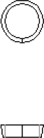
Right-click and choose Repeat Scale. Select all eight lines in the bottom view, including the green dashed lines. Be sure that you see
1 foundeach time. If necessary, use ZOOM Window to zoom in. Right-click to end object selection after you finish selecting the lines. Follow the prompts:Specify base point:
Use the Endpoint object snap at pointin Figure 9.8. Specify scale factor or [Copy/Reference] <0.400>:.4Save your drawing. It should look like Figure 9.8.
The CHANGE command changes the endpoint of a line and the radius of a circle. Note that you can also use grips and the Properties palette, both of which are covered in the next chapter, to change line endpoints and circle radii (among other object properties).
Note
You can use the CHANGE command to change text (which I cover in Chapter 13), the text and text properties of block attributes (not yet contained in a block), as well as the location and rotation of blocks (Chapter 18), but other newer commands do those jobs better. The Properties option of this command can change many object properties, but it's generally easier to use the Properties palette. However, these features of the CHANGE command can be useful when writing scripts or AutoLISP code, covered in Parts VI and VII of this book.
To change an object, select it and type change
Warning
The CHANGE command works differently, depending on whether you select lines or circles. For this reason, it can give unexpected results if you choose lines and circles at the same time.
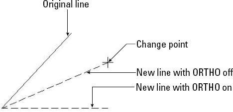
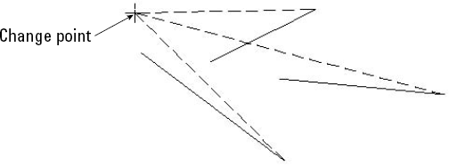
If you select one line, the CHANGE command changes the endpoint closest to where you picked the line. The command prompts you for a change point. When you pick the point, the command brings the endpoint of the line to that change point, as shown in Figure 9.9. You can use an object snap to specify the change point. If Ortho Mode is on, the line becomes orthogonal, bringing the endpoint of the line as close as possible to the change point that you specify, as shown in Figure 9.9.
If you select more than one line, CHANGE works differently: It moves the nearest endpoints of all the lines to the change point so that all the lines meet at one point, as shown in Figure 9.10.
Changing the radius of a circle has the same result as scaling it. When you select a circle, the command prompts you for a change point. AutoCAD or AutoCAD LT resizes the circle so that it passes through the new point. You can also press Enter. You then get a prompt to enter a new radius.
If you select more than one circle, the command moves from circle to circle, letting you specify a new radius for each, one at a time. You can tell which circle is current because of its drag image, which lets you drag the size of the circle.
If you've been following through this chapter's exercises, you've probably thought it tedious to pick several objects one at a time. Imagine trying to individually pick every object in a drawing just to move all the objects one-half unit to the left! Of course, there is a better way. In fact, AutoCAD and AutoCAD LT offer many ways of selecting objects. Selected objects are called the selection set of objects.
When you choose an editing command, you see the Select objects: prompt. This prompt has 18 options (16 if you are using AutoCAD LT) — all you could ever want for selecting objects — but these options are not shown on the command line or in the Dynamic Input prompt. To specify an option, type the option abbreviation. Because the Select objects: prompt repeats until you press Enter, you can combine options to select objects for any command. In the following list of options, the capitalized letters of the option are the abbreviation that you type (uppercase or lowercase letters work) at the Select objects: prompt.
Window. The Window option lets you pick two diagonal corners that define a window. All objects entirely within the window are selected. Figure 9.11 shows the process of picking the window on the left and the result on the right — to indicate that the selected objects are highlighted, they display dashed rather than continuous lines. As you move your mouse to specify the second diagonal corner, a blue transparent rectangle appears to help you preview which objects will be selected.
Tip
You can drag past the edge of the screen (actually the viewport) to specify a window. Hold down the mouse button and continue to move the mouse in the same direction. The display automatically pans so that you can see objects that were off the screen. When you see all the objects that you need to select, pick the second corner of the window.
Last. The Last option selects the last object created that is on a visible layer within the current view. (See Chapter 11 for more about layers.) Often you create an object and then want to move or copy it. In this situation, the Last option is an easy way to select the object that you just created.
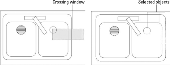
Crossing. Crossing enables you to pick two diagonal corners that define a window. All objects entirely or partly within the window are selected. As you move your mouse to specify the second diagonal corner, a green transparent rectangle appears to help you preview which objects will be selected. Figure 9.12 shows the process of picking the window on the left and the result on the right — the selected objects are highlighted.
Tip
You can drag past the edge of the screen (actually the viewport) to specify a crossing window. Hold down the mouse button and continue to move the mouse in the same direction. The display automatically pans so that you can see objects that were off the screen. After you see all the objects that you need to select, pick the second corner of the crossing window.
BOX. The BOX option is a combination of the Window and Crossing options. If you pick the two window corners from left to right, the selection functions as if you used the Window option. If you pick the two points from right to left, the selection functions as if you used the Crossing option. By default, you can select objects this way without specifying the BOX option. See the description of implied windowing later in this chapter.
ALL. The ALL option selects all objects on thawed and unlocked layers in the drawing. (I discuss layers in Chapter 11.) Use the ALL option when you want to select everything, including objects that you can't currently see on the screen.
Tip
To select all objects, choose Home tab

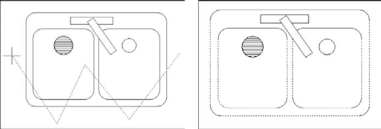
Fence. The Fence option enables you to specify a series of temporary lines to select any object crossing the lines. Figure 9.13 shows the process of defining a selection fence on the left and the result on the right — the selected objects are highlighted.
WPolygon. The Window Polygon option (WPolygon) is like the Window option, except that you create a polygon rather than a rectangular window. This option selects all objects that lie entirely within the polygon.
CPolygon. The Crossing Polygon option (CPolygon) is like the Crossing option, except that you create a polygon rather than a rectangular window. This option selects all objects that lie entirely or partly within the window.
Group. The Group option selects a named group of objects. (Chapter 10 covers groups.) If you need to work regularly with a certain set of objects, you can place them in a group and then easily select them with one click.
Remove. The Remove option enables you to deselect objects. After you use this option, all objects that you select are deselected and are therefore removed from the selection set. Use the Add option to once again select objects.
Tip
An alternative to using Remove to deselect objects is to press Shift and deselect objects by picking or implied windowing. Implied windowing is discussed later in this chapter.
Add. The Add option sets the selection mode to add objects to the selection set. Use the Add option after using the Remove option to start selecting objects again.
Multiple. The Multiple option turns off highlighting as you select objects. However, you cannot preview which objects are in the selection set.
Previous. The Previous option automatically selects all objects that you selected for the previous command. Objects selected and edited by using grips are not remembered for this option. (The next chapter covers grips.)
Undo. The Undo option deselects the object(s) selected at the last
Select objects:prompt. (If you removed objects from the selection set at the lastSelect objects:prompt, Undo reselects them.)AUto. The AUto option combines picking with the BOX option. By default, you can select objects this way without specifying this option. See the description of implied windowing later in this chapter.
SIngle. When you specify this option, you get another
Select objects:prompt. You select objects by using any option, and then AutoCAD immediately ends the selection process. You don't have to press Enter.SUbobject. The SUbobject option is used only for 3D solids and allows you to select vertices, edges, and faces. For more information, see Chapter 24. (AutoCAD only)
Object. This option ends the selection of subobjects so that you can select other objects. (AutoCAD only)

It may happen that you have many objects close together in a drawing, making it hard to select the object or point that you want. You could always zoom in, but in a complex drawing this can take some time. Another trick is to use object cycling. At the Select objects: prompt, place the cursor over the area where more than one object overlaps. Then hold down the Shift key and press the Spacebar. One object is highlighted. If it is not the one you want, with the Shift key still down, press the Spacebar again. AutoCAD or AutoCAD LT cycles through the objects. When the object that you want is highlighted, pick the object. You can continue to select other objects or end object selection by pressing Enter.
If you select objects before choosing a command, your options are more limited than if you choose a command first. Nevertheless, you have enough flexibility for most situations. The reason for the limitation is that the Command: prompt is active, and anything that you might type at the keyboard to indicate a selection option could be confused with a command. You can pick the object to highlight it, use implied windowing, or use the SELECT command on the command line to select objects in advance.
The purpose of the SELECT command is simply to select objects. This command then saves these objects for use with the Previous selection option. Choose an editing command and type p
Implied windowing is equivalent to the Auto selection option discussed earlier in this chapter. By default, implied windowing is always active. As a result, implied windowing is useful for selecting objects before or after choosing a command. By carefully choosing which way you create a selection window, you determine how you select objects:
From left to right. If the first window corner is to the left of the second one, you create a regular selection window. The window selects all objects entirely within the window.
From right to left. If the first window corner is to the right of the second one, you create a crossing window. The crossing window selects all objects that lie entirely or partially within the window.
Note
The drawing used in the following exercise on selecting objects, ab09-e.dwg, is in the Drawings folder on the DVD.
STEPS: Selecting Objects
Open
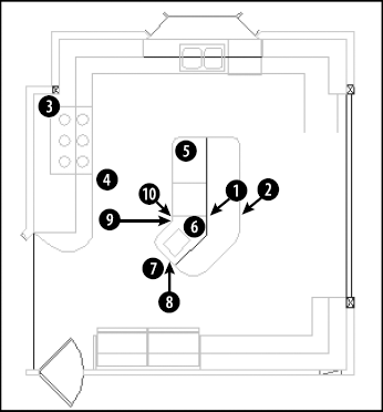
ab09-e.dwgfrom the DVD, as shown in Figure 9.14.Save the file as
ab09-06.dwgin yourAutoCAD Biblefolder. Make sure that Object Snap mode is on. Set running object snaps for Endpoint and Perpendicular.Draw a line from
Type select
To select the six-burner stovetop, pick a point near
To select the last object that was created — the line drawn in Step 1 — type l
Turn off Object Snap mode. To select the interior lines on the kitchen's island by using a fence, type f
Type r
Turn on Object Snap mode. Start the MOVE command. At the
Select objects:prompt, type pSave your drawing.
You can customize the way that you select objects. To do so, choose Application Button
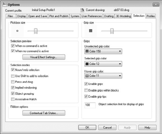
The pickbox is the box that you see at the intersection of the crosshairs when selecting (or picking) objects. The Pickbox Size area lets you set the size of the pickbox.
Note
If Noun/verb Selection is off and grips are disabled, no pickbox appears at the intersection of the crosshairs until you start an editing command and the command line displays the Select objects: prompt. However, if either Noun/verb Selection or grips are on, the pickbox is always at the crosshairs, letting you select objects at any time.
The Selection Preview option applies to rollover highlighting and the transparent selection rectangle. You can specify whether you want these effects to appear only if a command is active or even when no command is active (when you are selecting objects before choosing a command).
Click the Visual Effect Settings button to open the Visual Effect Settings dialog box, where you can specify the following settings:
Rollover highlighting. In the Selection Preview Effect section, you can choose the thicken effect, the dash effect, or both. The default is to show both. Click the Advanced Options button to exclude certain types of objects from the rollover highlighting effect. Some people find this effect distracting, but by customizing these settings, you may find a solution that works for you (other than turning it off).
Selection effect. In the Area Selection Effect section, you can turn the effect off, change the colors for the window, crossing rectangles, and polygons, and change the opacity percentage.
As you already know, the editing process consists of two parts: using a command, such as COPY or MOVE, and selecting objects. In AutoCAD/AutoCAD LT lingo, noun means an object in your drawing. Verb refers to a command because a command acts on an object. This option lets you decide whether you want to be able to select objects before starting a command.
In Windows programs, you typically select objects before starting a command. For example, if you're using Microsoft Word and want to erase a sentence, you select the sentence first, and then press Del.
By default, Noun/verb selection is active. With this option enabled, you can select objects first, without giving up the ability to choose commands first. This gives you maximum flexibility.
Most commands let you choose an object first, but a few don't because they require a specific order for selecting objects. For those commands, the selected object is ignored and you just follow the prompts.
The advantage of selecting objects first is that, when you switch between Windows programs, you don't have to change habitual ways of selecting objects. The disadvantage of selecting objects first is that some AutoCAD and AutoCAD LT commands don't let you select objects first, which can be confusing. Also, when you select objects first, grips appear — sometimes obscuring the objects that you need to select.
Use Shift to Add to Selection is the second option in the Selection Modes section of the Selection tab of the Options dialog box. By default, this option is not checked. In AutoCAD and AutoCAD LT, you often select more than one object at a time for editing. Therefore, the default lets you select object after object — when you select a second object, the first object stays selected. If you check the Use Shift to Add to Selection option, then after selecting one object, you must hold down Shift to select any additional objects.
One of the ways to select objects is to create a window that includes a number of objects. You're already familiar with creating a similar window from using ZOOM with the Window option. If the Press and Drag option is checked, you need to pick at one corner of the window and, without releasing the pick button, drag the cursor to the diagonally opposite corner. This type of action is typical of Windows programs.
By default, this option is not checked, which means that to create a window, you pick at one corner of the window, release the mouse button, and pick again at the diagonally opposite corner.
Implied windowing means that if you pick any point not on an object, AutoCAD or AutoCAD LT assumes that you want to create a selection window. By default, this option is on. You can then pick the opposite corner to select objects. If you pick the corners from left to right, you get a standard selection window. If you pick the corners from right to left, you get a crossing window.
This option applies only when you have started a command and see the Select objects: prompt. If you turn this option off, you can still enter the Window or Crossing selection options manually (by typing c
Groups are sets of objects that you name. Creating groups of objects is discussed in the next chapter. If object grouping is on (the default) when you select one object in a group, all the objects in the group are automatically selected. Object grouping is a global setting; you can also set object grouping on or off for individual groups.
If checked, the Associative Hatch option selects boundary objects when you select a hatch within the boundary. This option is off by default. Checking this option is equivalent to setting the PICKSTYLE system variable to 2. Chapter 16 covers hatches.
Note
The Ribbon Options section of the Selection tab lets you customize when certain ribbon tabs appear, based on the type of object selected or the active command. I cover this topic in Chapter 33.
All drawings need to be edited, either as part of the drawing process or to make corrections. In this chapter, you read about:
Erasing objects
Moving objects
Copying objects
Rotating objects
Scaling objects
Using the CHANGE command on lines and circles
The many ways of selecting objects
Customizing the object-selection features
The next chapter covers the more advanced editing commands and options.