
Shapes are text files that define a shape, or figure, that you can insert into your drawing. Shapes are similar to blocks in that you create, store, and insert them. They are different from blocks in the following ways:
Shapes are much harder to create.
Shapes are compiled into a format that conserves storage space, memory, and regeneration time.
You can use shapes to create fonts, and you can insert them into linetypes.
Like fonts, shape files are support files. If you distribute a drawing, then be sure to include any font or shape files that the drawing uses.
You can use shapes for simple outlines that you need to quickly insert many times. Some examples are shapes that are inserted into complex linetypes and font characters.
Note
AutoCAD LT doesn't offer the ability to create or insert shapes, but it will display shapes in a drawing if inserted with AutoCAD. This entire chapter applies to AutoCAD only.
Note
The Express Tools contain a command, MKSHAPE, which makes shapes for you. Choose Express Tools tab
Shape files are used for both shapes and fonts. You create them with a text editor and save them with the .shp file extension. You then use the COMPILE command (on the command line), which opens the Select Shape or Font File dialog box. Choose the .shp file and click Open. AutoCAD automatically compiles the file into a new file with the same name but with the .shx file extension. It then displays a message on the command line that the compilation has succeeded.
After you have compiled a shape file, you must load it with the LOAD command before you can place it in a drawing. The Select Shape File dialog box opens. Choose the SHX file and click Open. Font files don't have to be loaded because they're automatically referenced by text styles that use the font files.
To insert a shape, use the SHAPE command prompts as follows:
Enter shape name or [?]:Type the name of the shape, or type ?
Specify insertion point:Pick a point on the screen. AutoCAD drags the shape as you move the cursor.
Specify height <1.0000>:This functions like a scale factor. For example, type .5
Specify rotation angle <0>:Type a rotation angle.
Shape files and font files are essentially the same. In this section, I explain how to create shapes. At the end of the chapter, I explain the few distinctions necessary to create a font file.
As with many customizable files, you use a text editor to create shape files. You can add comments by preceding them with a semicolon. A shape definition has the following syntax:
*shapenumber,#ofspecs,SHAPENAME
spec1,spec2,...,0
The definition must start with an asterisk. Each line cannot contain more than 128 characters. Table 32.1 explains the parts of this shape definition.
Table 32.1. The Parts of a Shape Definition
Item | Explanation |
|---|---|
| You can use any number from 1 to 258. Each shape in a file must have a unique number. |
| This is the number of specifications in the second line of the definition, including the mandatory 0 at the end. Numbers grouped by parentheses are not counted as a single specification, but instead each number in parentheses is counted as one specification byte. For example, (0,−8,−127) counts as 3 specifications. |
| You must use uppercase for the shape name. This is the name you use with the SHAPE command. |
| This is a code that defines the actual shape. Each specification code defines a part of the shape, such as a line segment or an arc. Together, all the specifications draw the shape. |
| The definition must end with a 0. |
You can use two sets of codes to define a shape. The first set, the length and direction codes, only allows you to draw straight line segments. You use this system to create specifications in the three-character hexadecimal format.
The first character is 0, which tells AutoCAD that the next two characters are hexadecimal values.
The second character is a length in units. The maximum is 15 units. The number values can range from 0 to 9. For values from 10 to 15, use A to F. Keep in mind that the length is measured along the nearest X or Y distance. Therefore, diagonal lengths are not true lengths.
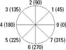
The third character is a direction code. Figure 32.1 shows how this code works. Use the code that represents the desired direction of the line from the start point.
Here is the code for the shape shown in Figure 32.2:
*2,4,PENNANT
044,02F,029,0
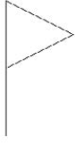
Here's how this shape works:
2is the shape's unique number.4is the number of bytes (specifications) on the second line of the definition.PENNANTis the shape's name.044draws the pole, a line that is 4 units in the vertical direction.02Fdraws the top line of the pennant, a line that is approximately 2 units in the F direction. (See the following note.)029draws the bottom line of the pennant, a line that is approximately 2 units in the 9 direction. (See the following note.)
Note
Although the length of the two diagonal lines was specified as 2, they're actually about 2.22 units long because the line endpoints snapped to the nearest imaginary grid point.
The length and direction codes have a number of limitations:
You can draw in only 16 directions.
The maximum length of a line is 15 units.
You can draw only straight line segments.
The shape has to be continuous; you cannot lift the "pen" up and start in a new place.
The second set of codes, called the supplemental shape codes, brings additional flexibility (and complexity) to your shapes. Table 32.2 lists these codes, which can be in either hexadecimal or decimal format.
Table 32.2. Supplemental Shape Codes
Decimal Code | Explanation | |
|---|---|---|
|
| Specifies the end of the shape definition. |
|
| Starts draw mode (puts the "pen" down). |
|
| Ends draw mode (lifts the "pen" up) so that you can move to a new location. |
|
| Divides the vector lengths by the specification that follows, as in 3,5 to divide the lengths by 5. This scales down the shape. You should reverse this at the end of the shape by using the |
|
| Multiplies the vector lengths by the specification that follows, as in 4,2 to multiply the lengths by 2. This scales up the shape. You should reverse this at the end of the shape by using the |
|
| Saves the current position so that you can return to it later in the shape definition. You must use (restore) every position that you save (with a maximum of four). |
|
| Restores the last saved position. |
|
| Draws another shape that is defined within the shape file whose number follows. For example, use 7,230 to draw shape 230. When the other shape is complete, AutoCAD returns to the current shape definition. |
|
| Draws a line specified by X and Y displacements that follow the code. For example, 8,(8,−12) draws a line whose endpoint is 8 units to the right and 12 units down from the current coordinate. You can add parentheses to your shape codes for readability. |
|
| Draws multiple X,Y displacements. You end this code with a displacement of 0,0. For example, 9,(8,−12),(1,0),(0,12),(−8,0),(0,0) draws four X,Y displacements. You can add parentheses to your shape codes for readability. |
|
| Draws an octant arc specified by its radius (ranging from 1 to 255), and a second code in the syntax |
|
| Draws a fractional arc that is not limited by octants specified by the five following codes in the syntax:
The start offset specifies how far past an octant the arc begins and is calculated as follows: (starting degrees – degrees of the last octant passed) * 256/45. The end offset specifies how far past an octant the arc ends and is calculated as follows: (ending degrees – degrees of the last octant passed) * 256/45. For both the start and the end of the arc, the last octant passed is specified in degrees, not the numbers in Figure 32.3, and is always a multiple of 45. The high radius is 0 unless the radius is more than 255. If your radius is larger, the high radius is the maximum number of 256 multiples in the value of the radius (for example, 2, if your radius is 600). The difference (the radius minus 256 times the high radius value, or 88 if your radius is 600) is placed in the radius specification. The radius is just the radius of the arc. The |
|
| Draws an arc using a system of X,Y displacement and bulge using the syntax X-displacement, Y-displacement, and bulge. These three codes can range from −127 to +127. The X and Y displacements just specify the endpoint of the arc. The bulge equals ((2 * H/D) * 127) where D is the chord length (the distance from the start point to the endpoint) and H is the height measured from the midpoint of the chord to the circumference of the arc. The bulge should be negative if the arc is drawn clockwise. |
|
| Draws multiple arcs using the X,Y displacement and bulge system. End the arcs with (0,0). You can use 0 for a bulge to place a line segment in the midst of several arcs. |
|
| This code is used only for text fonts that can be used in the vertical orientation (where each letter is drawn under the previous letter). When the vertical orientation is chosen, the specifications after this code are used. Use this code to move the starting and ending point of letters to a point appropriate for vertical orientation (that is, on top of and below the letter). See the "Creating Fonts" section later in this chapter for more information. |
The most common use for shapes is to create fonts. Here are a few examples:
*3,22,ALEF
010,07E,010,2,8,(−6,5),1,8,(−2,−4),01C,2,8,(5,2),1,8,(2,4),014,0
This is a squared-off alef, the first letter of the Hebrew alphabet, as shown in Figure 32.4. Displaying non-Roman fonts is a common use for shapes.
Planning in advance is almost essential. A common technique is to draw the shape in a drawing on a grid set to 1-unit spacing. You can use only integers in your shape codes, so you must often scale the shape up so that the smallest line segment is 1 unit.
Here's how the code for the alef works:
The shape starts at the top left. The code
010is a hexadecimal length and direction code that specifies a line with a length of 1 unit and a direction of 0 degrees.The second code,
07E, is also a hexadecimal length and direction code. It specifies a line with a length of 7 units in the E direction (315 degrees). Although the line is not actually 7 units long, its X (and in this case Y) distance is 7.The third code,
010, is the same as the first code and ends the first set of line segments.The fourth code,
2, lifts up the pen so that you can move to the start of the next line.The fifth code,
8, indicates that the following two codes will be an X,Y displacement.The sixth and seventh codes
(−6,5)are placed in parentheses for readability. They move the pen (while it is up) −6 units in the X direction and +5 units in the Y direction from the end of the last line to the start of the next line. (Count the grid dots to find it.)The eighth code,
1, puts the pen down so that you can draw.The ninth code,
8, is the same as the fifth code.The tenth and eleventh codes
(−2,−4)draw the first segment of the second line so that the endpoint is −2 units in the X direction and −4 units in the Y direction from the start point.The twelfth code,
01C, is a hexadecimal code and finishes the second line with a 1-unit line segment in the C direction (270 degrees).The thirteenth code,
2, lifts up the pen again.The fourteenth code,
8, is the same as the fifth code.The fifteenth and sixteenth codes
(5,2)move the pen (which is up) +5 units in the X direction and +2 units in the Y direction.The seventeenth code,
1, puts the pen down again.The eighteenth code,
8, is the same as the fifth code.The nineteenth and twentieth codes
(2,4)draw a line whose endpoint is 2 units in the X direction and 4 units in the Y direction from its start point.The twenty-first code,
014, is a hexadecimal length and vector code that draws a 1-unit line in the 4 (90-degree) direction.The twenty-second code,
0, ends the shape definition.
Here's another example, a script alef, as shown in Figure 32.5:
*4,10,S-ALEF
06C,2,8,(6,5),1,10,(3,016),0
Here's the explanation of the code for the script alef:
The first code,
06C, creates the line on the left, starting at the top and making it 6 units long.The second code,
2, lifts up the pen.The third code,
8, specifies an X,Y displacement, with the pen up.The fourth and fifth codes
(6,5)move the pen 6 units to the right and 5 units up, to the start of the arc.The sixth code,
10, introduces an octant arc.The seventh and eighth codes
(3,016)specify an arc with a radius of 3 units that starts at octant 1 and covers 6 octants (to octant 7). (See Figure 32.3 to review the octant codes.)The last code,
0, ends the definition.
Note
The drawing used in the following exercise on creating a shape, ab32-a.dwg, is in the Drawings folder on the DVD.
STEPS: Creating a Shape
Open
ab32-a.dwgfrom the DVD.Save the file as
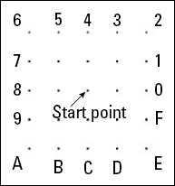
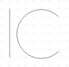
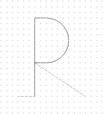
ab32-01.dwgin yourAutoCAD Biblefolder. This drawing shows an uppercase P, with dashed lines to indicate spaces before and after the letter, as shown in Figure 32.6. This is the type of drawing that you might use as a basis for creating a shape definition.Type notepad

Type the following in Notepad:
*80,15,UCP
2,030,1,0E4,020,12,(0,−8,−127),028,2,8,(9,−6),0
Press Enter at the end of the last line. Choose File

In AutoCAD, type compile
Type load
Enter shape name or [?]:
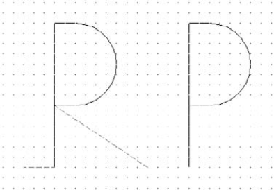
ucpSpecify insertion point:Pick any point. Specify height <1.0000>:Specify rotation angle <0>:Save your drawing. It should look like Figure 32.7.
You don't often get a shape right the first time, and you don't see the result until after you've compiled, loaded, and inserted the shape. Editing shape files involves the following steps:
Erase all copies of the shape.
Purge the
.shxfile by using the PURGE command and choosing Shapes in the dialog box. (You may sometimes need to purge more than once.) This step removes the existing shape definition from the drawing. If you forget this step, when you try to insert the corrected shape, AutoCAD uses the old definition!Edit the
.shpfile. Don't forget to change the#ofspecsvalue in the first line if necessary. Save the file.Recompile the
.shpfile.Reload the
.shxfile.Reinsert the shape by using the SHAPE command.
AutoCAD's support for TrueType fonts makes so many fonts available that the need to create your own is certainly less than with earlier versions. However, you might want to add special symbols to some existing fonts, especially if you often use these symbols within text.
Font files use the same codes to define the characters as shape files use. They have the following unique characteristics:
The
shapenumberpart of the definition must correspond to the ASCII code value for the character you're defining. To find these codes, look at the sample fonts in the Help file (from the InfoCenter toolbar, click the drop-down menu to the right of the Help button on the far right and then choose HelpThe
shapenamepart of the definition is lowercase and is usually used to label the character. For example, it usesucpfor uppercase p andlcrfor lowercase r. The sample files mentioned in the preceding item use these codes.The file must include a special shape identifier
UNIFONTthat defines the entire font, using the following syntax:*UNIFONT,4,font-name above,below,modes,0
The
abovevalue specifies how far above the baseline that uppercase letters extend. Thebelowvalue specifies how far below the baseline that lowercase letters, such as p or q, extend. Together, these two values define the size of the characters. AutoCAD uses these values to scale letters when you define a text height for the font. Modes should be 0 for a horizontal font and 2 for a font that supports both horizontal and vertical orientations. For example, a header for a font namedarchwith capital letters 21 units high and lowercase letters that extend 7 units below the line could be:*UNIFONT,4,arch 21,7,0,0
You must define the line feed (LF), which drops down one line without drawing so that lines of text can be placed beneath each other. The line feed is ASCII code 10.
You need to create a start point and endpoint with the pen up to create spacing between letters. See the previous exercise for an example.
As with all shapes, you probably want to use AutoCAD to draw all the characters on a grid with a spacing of 1. Decide on the height of the letters and be consistent.
In this chapter, you read about how to create shapes. You discovered how to:
Use shape files when you need to insert a shape many times, while using as little storage space as possible
Create fonts by using shape files with a few special codes that define both the font as a whole and each character
In the next chapter, I explain how to customize menus.