
Lines are the most commonly drawn object in 2D AutoCAD drawings — you'll use the LINE command a lot! Straight edges just happen to be very common in the real world. Related commands for drawing rectangles, polygons, and construction lines are also important, so you should have all these commands in your arsenal. This chapter explains how to draw all these types of objects.
The LINE command draws straight line segments. Part I includes several exercises in which you drew lines. However, the LINE command has several options, and you can still learn a few tricks of the trade by focusing on the actual LINE command.
If you continue to draw line segments, the subsequent prompts are different. Here's how to use them:
The command displays the
Specify next point or [Undo]:prompt for the next two segments. Right-click (or press the down-arrow key if you have Dynamic Input turned on) and choose Undo (or type u
After creating at least two line segments, the command displays the
Specify next point or [Close/Undo]:prompt. Right-click (or press the down-arrow key if you have Dynamic Input on) and choose Close (or type c
If you previously drew a line, press Enter at the Specify first point: prompt to start the line at the endpoint of the last line. If you most recently drew an arc, press Enter to start the line at the endpoint of the arc and draw it tangent to the arc.
STEPS: Using the LINE Command
Start a new drawing by using the
acad.dwtoracadlt.dwttemplate.Note
This exercise assumes that you have Dynamic Input on (click the Dynamic Input button on the status bar to turn it on, if necessary) and that you are using the default settings of polar format and relative coordinates. Make sure that the 2D Drafting & Annotation workspace is chosen from the Workspace Switching pop-up list on the status bar. Close any palettes that may be open.
Save the drawing in your
AutoCAD Biblefolder asab06-01.dwg.
Click the Ortho Mode button on the status bar.
Move the cursor to the right in the 0-degree direction and type .4667
Type .7341<129
Move the cursor to the right in the 0-degree direction and type .4668
Assume that this was a mistake. Type u
The
Specify next point or [Close/Undo]:prompt reappears. With the cursor still in the 0-degree direction, type .4667Type c
Start the LINE command again.
At the
Specify first point:prompt, press Enter. The line starts at the previous endpoint.Type .8071<270
Save your drawing. It should look like Figure 6.1.
Note
Other aspects of lines are covered elsewhere in this book. Chapter 11 explains how to draw dashed and dotted lines. Chapter 16 explains how to create polylines, which combine line segments and curves into one object. Chapter 16 also covers multilines and dlines — sets of parallel lines that you draw all at once. Chapter 21 discusses how to draw 3D lines and polylines.
The RECTANG command draws rectangles. Rectangles are used in all disciplines. The RECTANG command has a number of options that specify how the rectangle appears and how you define the rectangle's dimensions.
Specify first corner point or [Chamfer/Elevation/Fillet/Thickness/Width]:
Select one of the options. If you don't want to use any of the options, just specify one corner of the rectangle, using any method of specifying a coordinate.
Note
You can chamfer and fillet the corners as you create the rectangle. (Chapter 10 covers chamfering and filleting.) You can specify a width for the rectangle's line (see Chapter 16). You can also create a 3D box by using the elevation and thickness options (see Chapter 21). The RECTANG command creates a polyline, meaning that all four sides of the rectangle are one object, rather than four separate line objects. Chapter 16 covers polylines.
If you use one of the options, the first prompt returns so that you can specify the first corner point or use another option. After you specify the first point, you see the Specify other corner point or [Area/Dimensions/Rotation]: prompt.
To immediately create the rectangle, specify the corner diagonally opposite the first corner that you specified. You can use any method of specifying coordinates. For example, if you know that the rectangle should be 6 inches wide and 3 inches high, you can specify the second point as 6,3. (If Dynamic Input is turned off or set to absolute coordinates, add the @ symbol before the X,Y coordinates.) You can also use one of the options below:
Area. If you know the area of the rectangle, and only its length or width, then use this option. First you enter the area. Then you specify either the length or the width, and AutoCAD calculates the side that you didn't specify, based on the area you entered.
Dimensions. If you know the length and width of the rectangle, then use this option (although it may be simpler to specify the opposite corner, as I described earlier). You are prompted for the length and width. You then need to move the mouse to specify if you want the second corner to be above and to the right, or in any other direction from the first corner. When you see the rectangle you want, click it.
Rotation. If you want to rotate the rectangle as you create it, then simply enter a rotation angle and pick the opposite corner. Alternatively, instead of entering a rotation angle, you can pick two points to specify a rotation angle and then pick the opposite corner. This last option is great if you want to align the rectangle with an existing object.
First specify the number of sides. Then choose one of three methods of defining the polygon, as described in Table 6.1.
Table 6.1. POLYGON Command Options
If you type a number for the radius, then the bottom edge of the polygon is horizontal. However, if you pick a point for the radius with your mouse, you can specify the orientation of the polygon. As you rotate the mouse cursor around the center, you see the polygon rotate. Click when you like what you see.
Note
When you type a number for the radius, the bottom edge aligns with the snap rotation angle, which is usually 0. Chapter 8 explains how to change this angle.
The POLYGON command creates a polyline, meaning that the entire polygon is one object, rather than a series of line segments.
In the exercise that follows, I indicate inches with a double prime (″) and feet with a single prime (′). You may find this notation clearer when a measurement has both feet and inches, but you do not actually need to type the double prime for inches. When you have a measurement that is only in inches, it saves time to leave out the double prime.
Note
The drawing used in this exercise on drawing rectangles and polygons, ab06-a.dwg, is in the Drawings folder on the DVD.
STEPS: Drawing Rectangles and Polygons
Open
ab06-a.dwgfrom the DVD.Save the drawing in your
AutoCAD Biblefolder asab06-02.dwg. Verify that snap and grid are on, set at 1″. Object Snap should be off.Note
This exercise assumes that you have Dynamic Input on (click the Dynamic Input button on the status bar to turn it on, if necessary), that you use the default settings for the polar format and relative coordinates, and that you are in the default 2D Drafting & Annotation workspace (if necessary, click the Workspace Switching button on the status bar to choose it).

At the
Specify first corner point or [Chamfer/Elevation/Fillet/Thickness/Width]:prompt, move the cursor to 0′-1″,0′-1″ and click. At theSpecify other corner point or [Area/Dimensions/Rotation]:prompt, type 2′1″,1′9″Start the RECTANG command again. At the
Specify first corner point or [Chamfer/Elevation/Fillet/Thickness/Width]:prompt, Shift+right-click and choose the From object snap. Pick the bottom-left corner of the rectangle. At the<Offset>:prompt, type @2,2At the
Specify other corner point or [Area/Dimensions/Rotation]:prompt, type 1″9″,1′3″Right-click and choose Repeat RECTANG. At the prompt, find 0′8″,1′7″ (on a snap point) and click. At the
Specify other corner point or [Area/Dimensions/Rotation]:prompt, type 11,2Again, start the RECTANG command. At the prompt, find 1′1″,1′8″ and click. At the
Specify other corner point or [Area/Dimensions/Rotation]:prompt, type 1,-5
At the
Enter an option [Inscribed in circle/Circumscribed about circle] <I>:prompt, press Enter to accept the default. This means that you indicate the radius from the center to the vertices. (If your prompt shows<C>as the default, type iAt the
Specify radius of circle:prompt, type 1/2Repeat Steps 9 through 11, using a center of 1′5,1′8.
Start the POLYGON command again. At the
Enter number of sides <5>:prompt, type 3At the
Specify center of polygon or [Edge]:prompt, right-click and choose the Edge option.At the
Specify first endpoint of edge:prompt, choose the top-left corner of the faucet rectangle (1′1″,1′8″), which is on a snap point.At the
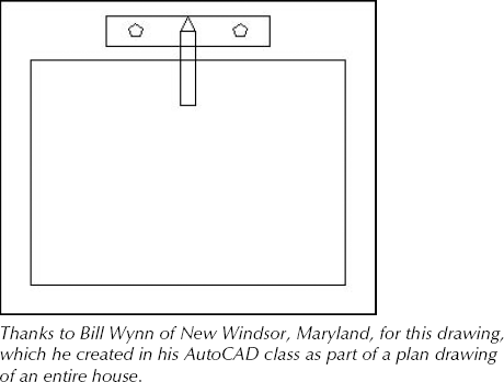
Specify second endpoint of edge:prompt, choose the top-right corner of the faucet rectangle to complete the triangle.Turn off the grid to get a better look at the drawing. You have completed the sink, which should look like Figure 6.2. Save your drawing.
Sometimes you want to create a line that is used solely for the purpose of reference. A construction line is a temporary or reference line used to help you draw or to show a relationship between objects. For example, you might want to do the following:
Draw two lines from the midpoints of two perpendicular lines so that you can use their intersection as the center for a circle.
Draw a line from one object to another to visually indicate the relationship between the two objects.
Show the relationship between equivalent parts of a model shown in front and right-side views.
Draw a line through the center of an object shown in cross-section so that you can show dimensions from the centerline to the edge of the object.
You could use regular lines for these purposes. However, construction lines (also known as xlines) are unique in that they extend infinitely in both directions. This makes them especially useful for seeing the relationships among various objects in your drawing.
Of course, construction lines are not actually infinite. However, they extend to the edge of the drawing area on your screen, and if you zoom out to see more of your drawing, they expand so that they always extend to the edge of the screen. The object snap tracking feature (covered in Chapter 4) sometimes eliminates the need for construction lines; nevertheless, sometimes you can work more easily having a line visible for several commands and then erasing it.
If you zoom to show the extents of your drawing, AutoCAD or AutoCAD LT ignores the xlines and shows you just the extents of the regular objects in your drawing. Chapter 8 covers the ZOOM command.
Specify a point or [Hor/Ver/Ang/Bisect/Offset]:
Table 6.2 lists the possible options. AutoCAD or AutoCAD LT continues to prompt you for more points so that you can continue to draw construction lines — much like the LINE command. Press Enter to end the command.
Table 6.2. XLINE Command Options
Option | Description |
|---|---|
Specify a point | This option enables you to define the construction line with two points. At the first prompt, specify a point. At the |
Hor | To draw a construction line parallel to the X axis, type h |
To draw a construction line parallel to the Y axis, type v | |
Ang | Type a |
Bisect | To draw a construction line that bisects an angle (divides the angle in half), type b |
Offset | To draw a construction line parallel to a line, type o |
Rays are similar to construction lines, except that they start at a specific point and extend to infinity in one direction only. If you need a line to extend in only one direction, using a ray may be less confusing.
Note
You can use most object snaps with construction lines and rays. (You can't use an endpoint for construction lines or a midpoint for rays.) You can edit construction lines and rays like any other object.
Note
The drawing used in this exercise on drawing construction lines and rays, ab06-b.dwg, is in the Drawings folder on the DVD.
STEPS: Drawing Construction Lines and Rays
Open
ab06-b.dwgfrom the DVD.Save the drawing as
ab06-03.dwgin yourAutoCAD Biblefolder.
At the
Specify a point or [Hor/Ver/Ang/Bisect/Offset]:prompt, choose point
At the
Specify through point:prompt, choose point
Press Enter to end the command. Notice that the drawing has been set up so that the construction line is drawn in green and with a noncontinuous linetype. This is to distinguish it from the main drawing. (See Chapter 11 for details on how to set up a drawing in this way.)

At the
Specify start point:prompt, choose point
At the
Specify through point:prompt, choose point
Save your drawing.
This chapter covered the ins and outs of lines. You read about:
Using the LINE command
Drawing rectangles
Drawing polygons
Creating construction lines, including xlines that extend infinitely in both directions and rays that extend infinitely in one direction
The next chapter explains how to draw curves and point objects. Curves include circles, arcs, ellipses, and donuts.