
Sometimes you need to refer to another drawing without inserting it. You may want to use part of another drawing as an example for your current drawing, or to see how the model in your drawing fits in with models in other drawings. You may want the flexibility of seeing the other drawing sometimes, but not seeing it at other times. Using an external reference is like laying one drawing on top of another and being able to see both at the same time. You can easily load and unload the other drawing.
External references, commonly called xrefs, enable you to view any drawing as a reference while in your current drawing. The external drawing is not part of your current drawing. The current drawing keeps track of the location and name of an external reference so that you can always reference it easily. As with blocks, you can snap to objects in the external reference, thereby using it as a reference for the drawing process. You can also change the visibility settings of the xref's layers.
Xrefs have several advantages over blocks:
Xrefs keep your drawing smaller than blocks. The externally referenced drawing doesn't become part of your drawing. Your drawing maintains only a reference (name and location) to the other drawing.
You always have the most updated version of the xref. Each time that you open a drawing, a current copy of the xref loads. By contrast, you would need to reinsert a file inserted as a block to see the most updated version.
In a team project, several people can use the same drawing as an xref, each having access to the latest changes.
Xrefs can be attached and detached easily for maximum flexibility, loaded and unloaded to display or hide them, or overlaid for temporary use. If you're only using the xref for reference, you may detach it before plotting.
The first step is to attach the external reference, which is just another drawing, to your current (host) drawing. You can underlay DWF and DWFx files, which are covered in Chapter 28, DGN and PDF files. I explain underlays at the end of this chapter.
Note
AutoCAD 2010 and AutoCAD LT 2010 can now use PDF files (created by publishing a drawing to a PDF file with the PUBLISH or PLOT command or from an application such as Adobe Acrobat) as underlays. I discuss PDF files further in Chapter 28. AutoCAD 2010 and AutoCAD LT 2010 also introduce a number of new commands and system variables to simplify working with external references and underlays.
To attach an xref of an AutoCAD or AutoCAD LT drawing, follow these steps:

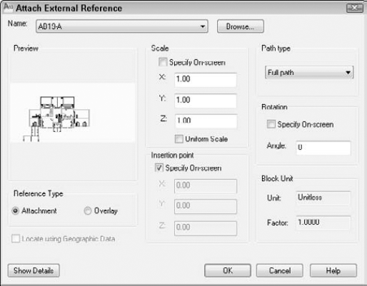
Choose the file you want to attach and click Open. The Attach External Reference dialog box (shown in Figure 19.1) opens. This dialog box displays the file that you chose, along with its path (location).
Choose the type of xref that you want in the Reference Type section:
Attachment. Use an attachment when you want to be sure that the xref will be displayed if someone else xrefs your current drawing. In other words, that person will see your current drawing, and your xref will be nested within it.
Overlay. Use an overlay when you're sharing drawings in a networked environment and you don't want to change your drawing by attaching an xref. If someone else attaches your drawing while you're working on it, the overlay is not displayed.
From the Path Type drop-down list, choose the type of path that you want to use:
Full path. Specifies the full path of the xref drawing, including the drive letter (such as
c:).Relative path. Specifies only part of the xref drawing's path, and uses the current drive or folder. This option enables you to move a host drawing and its xrefs to a different drive that has the same folder structure.
No path. Uses the current folder of the host drawing. This option enables you to use an xref when you move the drawing; for example, when you send it to someone else with a different folder structure. To make sure that the drawing can find the xref, ensure that it is in the project files search path or in the same folder as the host drawing.
Use the bottom half of the dialog box to specify the insertion point, the X, Y, and Z scale factors, and the rotation angle, either in the dialog box or on-screen. These prompts are the same ones that you use when inserting a block or file.
Note
A check box in the Scale section lets you specify a uniform scale, so the Y and Z values are always the same as the X value. The Block Unit section displays the units set for the referenced drawing. This is the same setting you use when you create a block and allows for the automatic scaling of the drawing. You can set this value after the INSUNITS system variable or by entering units

Click OK to attach the xref.
If your current view does not show the entire xref, do a ZOOM Extents (choose View tab
Note
You can also attach an xref from a tool palette. For more information on tool palettes, see Chapter 26.
After you have the xref in your drawing, you can start to work. The xref is like a block, although you cannot explode it. However, you can use object snaps on all the objects in an xref, just as you can with blocks. This enables you to use the xref as a basis for your own drawing.
Sometimes you need to open the xref to work on it directly. For example, you may see an error that you want to correct. The XOPEN command opens xrefs. The easiest way to use XOPEN is to click the xref to select it in your drawing, right-click, and choose Open Xref. The xref opens in its own drawing window.
To see what type of xrefs you have in your drawing, choose View tab
Images. Any type of bitmap (raster) image that you can import. (See Chapter 27 for more information.)
DWF underlays. DWF and DWFx files that act like xrefs. I explain how to attach DWF files at the end of this chapter, and I cover creating DWF and DWFx files in Chapter 28.
DGN underlays. DGN files (MicroStation drawings) that act like xrefs. I cover DGN files at the end of this chapter.
PDF underlays. PDF files that act like underlays. I explain how to attach PDF files at the end of this chapter, and I cover creating PDF files in Chapter 28.
Note
The External References palette replaced the Xref Manager as of AutoCAD 2007 and AutoCAD LT 2007. You can open the earlier Xref Manager with the CLASSICXREF command.
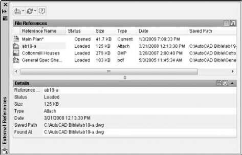
Figure 19.2. The External References palette displays referenced drawings, raster images, DWF and DWFx files, DGN drawings, and PDF files.
The palette lists all the referenced drawings and files. You can choose one of two views, using the buttons at the top-right corner of the palette:
Tip
You can change the width of the columns in List view by placing the cursor on a column dividing line until it changes to a two-headed arrow. Then drag in either direction. You can also double-click the dividing line between two columns to automatically resize the column to the left based on the widest value.
When you click any xref, you see a preview tooltip that shows the reference and lists its details. You can control the preview format to display a preview thumbnail, file details, or a combination. Right-click in the palette, choose Tooltip Style, and choose one of the options.
If you move or delete a referenced item, the External References palette notes that the file is not found. To troubleshoot, it helps to know where it searches for xrefs. The External References palette searches for references according to a specific order:
Path specified. Locates the specified path xref.
Current folder. Locates the current folder of the host drawing.
Project path. The path for external references. To check or change the project path, choose Application menu

Support path. The location for support files. To check or change the support path, choose Application menu
Start-in folder. To find the start-in folder, right-click your AutoCAD 2010 or AutoCAD LT 2010 desktop shortcut and choose Properties.
Note
The drawings used in the following exercise on attaching xrefs, ab19-a.dwg and ab19-b.dwg, are in the Drawings folder on the DVD.
STEPS: Attaching Xrefs
Open
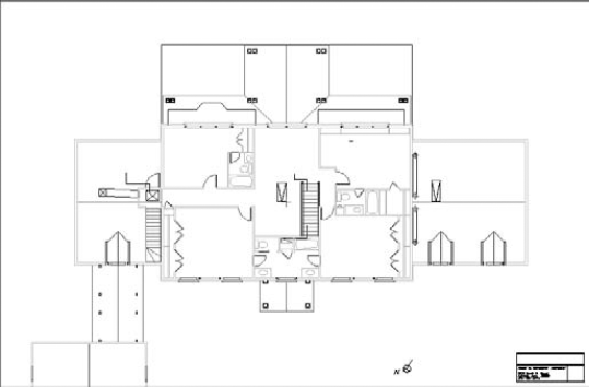
ab19-a.dwgfrom the DVD. This is the floor plan for a house.Open Windows Explorer (right-click Start on the task bar and choose Explore). Copy
ab19-b.dwgfrom the DVD to yourAutoCAD Biblefolder.
In the Attach External Reference dialog box, you see the filename displayed. Make sure that all Specify On-Screen check boxes are unchecked, and click OK. You see
ab19-b.dwg, which is a titleblock, inab19-a.dwg.Save the drawing as
ab19-01.dwgin yourAutoCAD Biblefolder. Click the drawing's Close box to close the drawing.Start a new drawing, using the
acad.dwtoracadlt.dwttemplate. On the command line, type unitsAgain choose Insert tab
In the Attach External Reference dialog box, you see the filename displayed. Leave the defaults and click OK. Choose View tab
Attach Xref "ab19-01": C:AutoCAD Bibleab19-01.dwg
"ab19-01" loaded.
Attach Xref "ab19-b": C:AutoCAD Bibleab19-b.dwg
"ab19-b" loaded.
To help you visualize the relationships among the three drawings, click the dialog box launcher at the right end of the panel's title bar. The External References palette lists both drawings. Click Tree View at the top-right corner of the palette. You now see the two xrefs listed in a tree structure, showing their relationship more clearly. Close or auto-hide the palette.
Save your drawing. It should look like Figure 19.3.
While you're working in a drawing with an external reference, you may decide that the external reference needs some modification. The same may apply if you inserted a file as a block. You can make changes to the xref or block and save those changes back to the original drawing. You can even transfer objects from your drawing to the xref or block, and vice versa. This feature is called in-place editing.
Note
AutoCAD LT 2010 introduces the ability to use in-place editing with xrefs. Prior to AutoCAD LT 2010, you had to open the original file and modify it.
As you click each of the available references, its preview appears at the right. If the xref has nested objects, choose one of the following options (if it does not, then ignore this section of the dialog box):
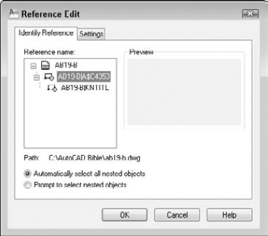
Figure 19.4. The Reference Edit dialog box enables you to choose which reference you want to edit, including nested references.
For more control, click the Settings tab to set the following options:
Create unique layer, style, and block names. Displays layer, style, and block names with a prefix of $#$, to help distinguish them from the named items in your main drawing.
Display attribute definitions for editing. Enables you to edit attribute definitions of blocks with attributes. (See Chapter 18 for details on attributes.)
Lock objects not in working set. Locks objects in the host drawing so that you can't accidentally modify them.
Click OK to close the Reference Edit dialog box.
Note
If the reference comes from an earlier release, you see a warning that if you save your changes back to the xref, that xref will be updated to the current file format for the release, which is the AutoCAD 2010 format.
If you checked the Prompt to Select Nested Objects option, you see a prompt to select nested objects. Complete object selection to define the working set, that is, the objects that you can edit. Other objects are faded by 50 percent (this is the default, determined by the XFADECTL system variable).
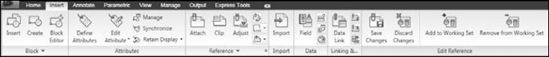
The Edit Reference panel appears on the current tab, shown in Figure 19.5, and you see the message Use REFCLOSE or the Refedit toolbar to end reference editing session on the command line. You're now ready to edit the xref or block.
There are several types of edits that you can make on the working set of objects from the xref or block:
If you change an object's properties, such as its layer, the object will have the new object property.
If you erase an object, the object is deleted from the xref or block.
If you draw a new object, the object is added to the xref or block. An exception is if you create a new object by editing objects outside the working set. For example, if you break a line (not in the working set) into two lines, then nothing is added to the working set.


When you save changes to a block, block definitions are redefined and all instances of the block are regenerated according to the new definition. If you gave an xref object properties that don't exist in the xref, such as a layer, the new property is copied to the xref so that the object can keep that property.
Note
The drawings used in the following exercise on editing an xref in place, ab19-a.dwg and ab19-b.dwg, are in the Drawings folder on the DVD.
STEPS: Editing an Xref in Place
Open
ab19-a.dwgfrom the DVD. Save it asab19-03.dwgin yourAutoCAD Biblefolder.Open
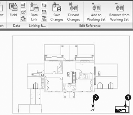
ab19-b.dwgfrom the DVD. Save it asab19-04.dwgin yourAutoCAD Biblefolder. Click the Close box ofab19-04.dwgto close the drawing (but not the program), leavingab19-03.dwgon your screen.Choose Insert tab
Double-click the titleblock. The Reference Edit dialog box opens. Choose
ab19-04.dwg. It is displayed in the preview box. Click OK. The Edit Reference panel appears, and you can now edit the xref. Your drawing should look like Figure 19.6.Select the titleblock again and choose Explode.
Choose Annotate tab
Type Davis Floor Plan and press Enter twice to end the command.
Choose the text (the name and address of the architect) at the bottom of the titleblock and change its color to red to make it stand out.


The following symbols will be permanently bound to the current drawing:
Layers: $0$TITLEBLK
Text Styles: $0$ROMANS, $0$ROMAND
Blocks: $0$KNTITL

Enter option [Save/Discard reference changes] <Save>: _sav
Regenerating model.
11 objects added to ab19-04
1 object removed from ab19-04
1 xref instance updated
ab19-04 redefined and reloaded.
Choose View tab
To see the results of the editing on the xref, open
ab19-04.dwg. You can see the changes in the titleblock text and that the North symbol and letter are gone.Close both drawings, saving changes to
ab19-03.dwg.
You can control the display of xref layers so that you see only those layers you need. Several features let you control the process of displaying xrefs, making it easier to see only part of an xref and speeding up the display of very large xrefs.
Dependent symbols are named items in a drawing, such as layers, text styles, dimension styles, and so on. When you attach an xref, these symbols are listed in your current drawing. For example, the Layer Control drop-down list displays the layers of the xref. Xref symbols have the format xref_name|symbol_name. This system distinguishes xref symbols from those of your current drawing and ensures that there are no duplicate symbols.
You can turn on and off, or freeze and thaw, xref layers. You can also change an xref layer's properties in the Layer Properties Manager palette. By default, these changes are retained. However, you can set the VISRETAIN system variable to 0 to discard these changes. The next time you open the drawing or reload the xref, the original settings are restored.
Objects created on layer 0 do not take on the typical xref layer name format, but stay on layer 0. If objects in the xref are on layer 0 with the color and linetype set to ByLayer, they take on the color and linetype properties of the current layer in the current drawing. If color and linetype are set to ByBlock, then objects assume the current properties when the xref is attached. If you explicitly set color and linetype, then objects retain those settings.
You can use the XBIND command to import only the symbols that you want from the external reference into the current drawing. This makes it easy to work with a consistent set of symbols in the current drawing and the xrefs. For example, you can choose to import the titleblk layer and the dec dimension style. On the command line, type xbind
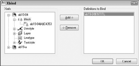
Click the plus sign next to any symbol type to open a list of symbols. Click the one you want and choose Add to add it to the Definitions to Bind list. Click OK when you're done.
Later in this chapter, I explain how you can use the DesignCenter to move xrefs and other dependent symbols from one drawing to another.
If drawing a includes drawing b as an xref and drawing b includes drawing a as an xref, then you have a circular reference. Circular references can exist among three or more xrefs when you have nested xrefs. The program detects circular references and loads as much as it can. If you try to load an xref in such a situation, you see the following message:
Warning: Circular reference from XREF to current drawing.
Circular reference(s) have been found. Continue? <N> Type y to continue to load the xref.
Breaking circular reference from XREF to current drawing.
You may want to see only part of an xref. This option is especially important when you're using very large xref drawings. The CLIP and XCLIP commands enable you to create a border in an xref, and hides any part of the xref outside the border.
Note
AutoCAD LT 2010 now supports the ability to clip xrefs. To clip xrefs in AutoCAD or AutoCAD LT, you can use the XCLIP command, which works with xrefs only, or the new CLIP command, which supports xrefs, raster images, and underlays.
Table 19.1 explains the options of this command.
Table 19.1. XCLIP Options
Option | How to Use It |
|---|---|
ON | Turns the clipping boundary on, displaying only the portion of the xref inside the clipping boundary. By default, the clipping boundary is on. Use this after you've turned it off to see only the clipped portion again. |
OFF | Turns the clipping boundary off, displaying the entire xref. The clipping boundary is still retained. This is somewhat like turning off a layer. You may want to see the entire xref for a while (for example, while redefining the boundary). Then you can turn the boundary back on (using the ON option) when you need only the clipped portion again. |
Clipdepth | This is used for 3D drawings only. After you set a clipping boundary, you can set front and back planes parallel to the boundary to display only the portion of the xref within that three-dimensional space. You create the front and baplanes by specifying a distance from the clipping boundary. The Remove suboption removes the clipping planes. |
Deletes the clipping boundary. The boundary is no longer retained in the drawing. | |
generate Polyline | Creates a polyline from the clipping boundary, using the current layer, color, and linetype. If you want to change the clipping boundary, you can edit the polyline by using PEDIT and redefine the boundary with the new polyline. |
New boundary | This is the default option. Press Enter to see the suboptions, which follow. |
Select polyline | Enables you to specify the clipping boundary by selecting an existing polyline. This option decurves fit-curved or arc portions of the polyline when creating the boundary. | |
Polygonal | Enables you to specify a polygonal area, such as a polyline with straight edges. This option creates a rubber-band line as you pick points, keeping the polygon closed. You can use this option to create an irregularly shaped area that includes only the portion of the xref that you want to see. | |
Rectangular | Enables you to pick two points on diagonally opposite corners of a rectangle, such as creating a selection window. | |
Invert clip | Enables you to hide any part of the xref inside the border. After choosing this suboption, choose one of the previous suboptions to define the clipping boundary. |
To see the clipping boundary (if you haven't used an existing polyline to define it), change the value of the XCLIPFRAME system variable to 1. When you do so, you can select the boundary and modify it by using its grips. You can also click the blue arrow to invert the clip.
Note
You can use the FRAME system variable to override the setting of the XCLIPFRAME system variable and the frame settings for all raster images and underlays in a drawing. Setting FRAME to 3 allows you to control the frame display by object type (xref, raster image, and underlays) individually. The frame settings for underlays are covered later in this chapter.
Figure 19.8 shows an xref clipped with a polygonal boundary.
In order to reduce the time needed to display large xrefs, such as those used in GIS or 3D drawings, you can use demand loading. This feature enables you to load only the objects necessary to display the xref in your drawing. Demand loading works together with spatial and layer indexes.
The spatial index is created when you save a drawing. This index is used when you have enabled demand loading and attach a clipped xref that was saved with a spatial index. The index determines how much of the xref needs to be read to display it.
The layer index is also created when you save a drawing. This index is used when you've enabled demand loading and attach an xref that was saved with a layer index and has frozen or turned off layers. The index determines how much of the xref needs to be read to display it.
To make it perfectly clear, you need all the following in order to use demand loading:
Demand loading must be enabled in the current drawing.
The xref must have been saved with a spatial and/or layer index.
The xref must either be clipped (for a spatial index) or have layers that are frozen or turned off (for a layer index).
Note
Demand loading is similar to partial opening and loading of drawings, explained in Chapter 8.
You can turn on demand loading in your current drawing. To turn on demand loading, choose Applications Button
You save a spatial index for a drawing that you expect to use as an xref. The saving process takes a little longer, but you save time at the other end when you load a clipped xref or clip an xref for the first time. To create a spatial index in AutoCAD, choose Application Button
From the Index Type drop-down list, choose Spatial or Layer & Spatial. Click OK. Then click Save in the Save Drawing As dialog box. In AutoCAD LT, use the INDEXCTL system variable on the command line and set its value to 2 for just a spatial index, or to 3 for both spatial and layer indexes.
Tip
If you want to create an index for an existing drawing, click OK once to return to the Save Drawing As dialog box. Click Cancel. In other words, you don't have to actually save the drawing to set up the index, which is controlled by the INDEXCTL system variable.
After you create a spatial index, each time you save the drawing, you see the following message:
Updating Indexes for block *MODEL_SPACE
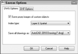
Figure 19.9. The DWG Options tab of the Saveas Options dialog box enables you to save spatial and layer indexes.
To stop saving the index each time you save in AutoCAD, choose Application Button
You save a layer index for a drawing that you expect to use as an xref to create an index of all the layers in the drawing. As with a spatial index, the saving process takes a little longer, but you save time at the other end when you load an xref with frozen or turned off layers. To create a layer index in AutoCAD, choose Application Button
From the Index Type drop-down list, choose Layer or Layer & Spatial. Click OK, and then click Cancel. In AutoCAD LT, set the INDEXCTL system variable to 1 for just a layer index, or to 3 for both layer and spatial indexes.
After you create a layer index, each time you save the drawing, you see the following message:
Updating Indexes for block *MODEL_SPACE
To stop saving the index in AutoCAD, choose Application Button
Note
The drawings used in the following exercise on controlling xref display — ab19-a.dwg, ab19-b.dwg, ab19-01.dwg, and ab19-02.dwg — are in the Drawings and Results folders on the DVD.
STEPS: Controlling Xref Display
Open
ab19-01.dwgfrom yourAutoCAD Biblefolder if you did the first exercise in this chapter.If you didn't do the first exercise in this chapter, use Windows Explorer to find
ab19-b.dwgin theDrawingsfolder on the DVD andab19-01.dwgandab19-02.dwgin theResultsfolder on the DVD. Copy all three files to yourAutoCAD Biblefolder. In Windows Explorer, right-click each file and choose Properties. Uncheck the Read-Only option (if checked) and click OK. Then openab19-01.dwgfrom yourAutoCAD Biblefolder.If you get a message that the drawing cannot find the xrefs and you are using AutoCAD, you can choose Application Button
To create layer and spatial indexes, do one of the following:
If you have AutoCAD. Choose Application Button
If you have AutoCAD LT. On the command line, enter indexctl
Choose Save from the Quick Access toolbar. Note the message on the command line that the indexes are being updated.
Close
ab19-01.dwg.Open
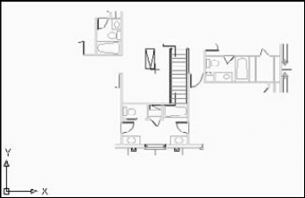
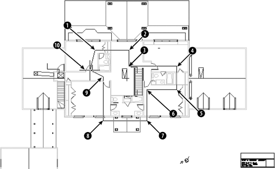
ab19-02.dwgfrom yourAutoCAD Biblefolder. This drawing has an attached xref of a house plan and a nested xref of a titleblock, as shown in Figure 19.10.Save it as
ab19-05.dwgin yourAutoCAD Biblefolder.Choose Application Button
Click the Layer Control drop-down list. Click the On/Off icon next to the
Ab19-01|noteslayer to turn the layer back on. Click the top of the drop-down list box to close it. The notes layer displays.
Select objects:
Pick anywhere on the xref in Figure 19.10. Select objects:Enter clipping option [ON/OFF/Clipdepth/Delete/generate Polyline/New boundary] <New>:Specify clipping boundary: [Select polyline/Polygonal/Rectangular/Invert clip] <Rectangular>:Right-click and choose Polygonal. Specify first point:Pick
in Figure 19.10. (It might help to turn off Object Snap if it is on.)Specify next point or [Undo]:Pick. Specify next point or [Undo]:
Pick. Specify next point or [Undo]:
Pick. Specify next point or [Undo]:
Pick. Specify next point or [Undo]:
Pick. Specify next point or [Undo]:
Pick. Specify next point or [Undo]:
Pick. Specify next point or [Undo]:
Pick. Specify next point or [Undo]:
Pick. Specify next point or [Undo]:
This action clips the xref.
Turn off the
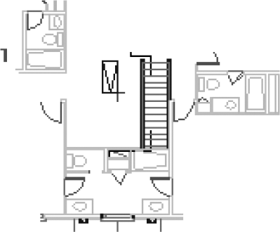
Ab19-01|noteslayer again.Save your drawing. It should look like Figure 19.11. Keep the drawing open if you're continuing on to the next exercise.
If you have many xrefs in a drawing, you need a way to keep track of them and their relationships to your drawing. You have several techniques for managing xrefs. The External References palette, DesignCenter, and the xref notification feature are all tools to help you with this task.
Tip
Though it may be obvious, the first principle of managing xrefs is to keep them simple. Overly complex nested configurations are hard to manage, no matter what you do.
The External References palette is designed to let you manage xrefs (as well as DWF, DWFx, DGN, and PDF underlays and images) from one place. I explain the features of the External References palette in Table 19.2. You access these features by right-clicking a reference and choosing from the shortcut menu.
Table 19.2. External References Palette Features
Bind | When creating a block from the xref, this feature changes named layers, text styles, dimension styles, and so on (called symbols) from the format | |
Insert | When creating a block from the xref, this feature removes the |
Open | Opens the selected xref in a new drawing window. |
Xref Found At | Specifies where the xref was actually found, which may be different from the saved path. You can then click Save Path to save the current path. If the location of an xref is changed and is not in the Support Files or Project Files search path, the status of the xref displays as Not Found. Use the Browse button to find and open the xref and click Save Path. Click OK to automatically reload the xref. |
Note
You cannot bind or detach nested xrefs without binding the parent xref.
You can also click the Refresh button to refresh the selected reference, or use its down button to choose Reload All References.
Note
Express Tools offer two commands that can help you work with xrefs. Choose Express Tools tab
If an xref is moved or renamed while you have it displayed in an open drawing, you need to reload it. An xref can change if someone else on your network opens and edits it while you're using it. External Reference Notification offers instant notification if an xref changes.
As explained in earlier chapters, you can use the DesignCenter to move named objects, including xrefs, from one drawing to another. (I cover the DesignCenter in detail in Chapter 26.) To insert an xref from another drawing, press Ctrl+2. Navigate to the drawing and double-click it to open the list of named objects. Double-click Xrefs to see a list of xrefs in the right pane.
Double-click the xref that you want to insert. The Attach External Reference dialog box opens (refer to Figure 19.1) so that you can insert the xref. You can also right-click and choose Attach as Xref, or right-click and drag a drawing from the DesignCenter into your drawing.
If you set the XREFCTL system variable to 1 (by default, it's set to 0), a copy of all xref activity for your current drawing is saved in an ASCII text file. You can read the log to troubleshoot problems that may occur. The log file goes in the same folder as your drawing and uses your drawing name with the .xlg filename extension. This file can become long. Therefore, once in a while, you should delete all or part of the file.
Note
The Reference Manager is a stand-alone program that manages xrefs, images, fonts, and plot configurations, which are all outside files that are referenced in your drawing. See Chapter 26 for full coverage of the Reference Manager. The Reference Manager is only available if you have AutoCAD.
Note
The drawing used in the following exercise on managing xrefs, ab19-05.dwg, is in the Results folder on the DVD.
STEPS: Managing Xrefs
Use
ab19-05.dwgfrom yourAutoCAD Biblefolder if you did the previous exercise. Otherwise, open it from theResultsfolder of the DVD.Save it as
ab19-06.dwgin yourAutoCAD Biblefolder.
Choose View tab
Right-click
ab19-bagain. Choose Reload to reload the xref.This time right-click
ab19-01. Choose Bind. In the Bind Xrefs dialog box, choose Insert and click OK. This action inserts both xrefs (ab19-01andab19-b) as blocks. (Click the Layer Control drop-down list to see that there are no xref-type layer names.)Save your drawing.
You can use DWF, DGN, and PDF files as underlays, which are similar to xrefs. A DWF file is an accurate, compressed vector image representation of a drawing, and I explain how to create DWF and DWFx files in Chapter 28. DGN files are drawings created with Bentley MicroStation®, another CAD program. You can produce PDF files by plotting or publishing a drawing, or by using an application such as Adobe Acrobat.
Note
AutoCAD 2010 and AutoCAD LT 2010 now allow you to underlay PDF files like you can underlay DWF and DGN files. To simplify attaching and modifying underlays, a set of new commands and system variables have been introduced. The new commands are ADJUST, ATTACH, CLIP, and ULAYERS, while the new system variables introduced to work with underlays are FRAME and UOSNAP.
Underlays are different from xrefs in that you cannot bind them to a drawing file. The primary reasoning for this is that you use underlays as reference documents that you might not be able to obtain as a DWG file. Underlays also help to protect the original owner's investment and integrity in the design or information contained in the original document.
Attaching a DWF file is similar to attaching an xref or inserting a block. To attach a DWF file, follow these steps:

In the Select Reference File dialog box, choose the DWF or DWFx file and click Open.
In the Attach DWF Underlay dialog box, choose a sheet from the DWF or DWFx file, if it contains more than one page. The Attach DWF Underlay dialog box is similar to the Attach External Reference dialog box shown in Figure 19.1.
From the Path Type drop-down list, choose the type of path you want to specify for the underlay. (See the "Attaching an external reference" section earlier in this chapter for more information.)
To specify the insertion point, scale, and rotation, uncheck the respective check boxes in the dialog box; otherwise, specify them on-screen.
Click OK to attach the DWF or DWFx file as a DWF underlay.
If your current view does not show the entire underlay, use ZOOM Extents to see it (choose View tab
If the drawing has more than one model, choose the one you want to attach from the Select a Design Model from the DGN File list box. DGN files can have master units (Imperial or metric) and another set of units, called sub units. Choose which one you want to use. AutoCAD converts one unit (either master or sub) to one drawing unit. Click OK to attach the DGN underlay.
After an underlay is created, you can control its display and how you can work with the underlay's geometry.
You can change the appearance of an underlay to make it more or less prominent, by using the ADJUST command. This command has three options:
Fade. Blends the underlay more or less with the background color. You can choose a value from 0 to 100, where 100 fades the underlay completely with the background. The default value is 0 for images and PDF underlays and 25 for DWF and DGN underlays.
Contrast. Increases or decreases the contrast of the colors. The values range from 0 to 100, where 100 changes the colors to their closest primary or secondary color. The default is 50 for images and 75 for DWF and DGN underlays, and 100 for PDF underlays.
Monochrome. Displays the underlay as shades of gray. Choose Yes or No.
If you selected a single underlay, the default values for Fade, Contrast, and Monochrome are the current property settings of the selected underlay. If you select multiple underlays, the default values for Fade, Contrast, and Monochrome remain as they were set the last time the command was used.
If the underlay is large, you may not want to view all of it in your drawing. You can clip an underlay in the same way that you can clip an xref or block, by using the CLIP command. To access this command, choose Insert tab
ON. Turns on an existing clipping boundary. By default, a clipping boundary is on.
OFF. Turns off an existing clipping boundary so that you can see the entire underlay.
Delete. Deletes a clipping boundary.
New boundary. Creates a new rectangular or polygonal clipping boundary.
You can turn the display of the frame for an underlay on or off. This is very similar to the frame that is displayed after clipping an xref or block. If the underlay is not clipped, the frame shows the rectangular border of the entire underlay. If you clipped the underlay, the frame shows the clipping border.
To display the frames for all underlays in a drawing, use the FRAME system variable and set its value to 1 (displays the frame and plots it) or 2 (displays the frame, but doesn't plot it). To turn off the display of all frames, set the value to 0. Even with the frames turned off, you can select an underlay. To change the display of the frames for underlays, choose Insert tab
Note
The FRAME system variable allows you to control the display of the frames for all xrefs, underlays, and raster images attached to a drawing, regardless of the settings of the other frame-related system variables.
When FRAME is set to 3, you can control the frame display for xrefs, underlay's, and raster images in the drawing by using the appropriate system variable. Use the following system variables to control the display of the frames for underlays; except for value 3, they support the same values as FRAME:
DWFFRAME. Controls the frame display for DWF underlays.
DGNFRAME. Controls the frame display for DGN underlays.
PDFFRAME. Controls the frame display for PDF underlays.
By default, you can use object snaps with underlays. If you need to use the object snaps of your underlay, this is the ideal setting. In PDF underlays, object snaps only work with vector-based objects; they do not work with raster-based (bitmap) objects.
However, if you don't want to use object snaps with underlays or you find yourself getting "caught" on an underlay's object snaps, you can turn object snaps off. To change the status of object snaps for underlays, choose Insert tab
Note
The UOSNAP system variable is new for AutoCAD 2010 and AutoCAD LT 2010.
You can control the use of object snaps by underlay type, using the following system variables:
DWFOSNAP. Controls the use of object snapping with DWF underlays.
DGNOSNAP. Controls the use of object snapping with DGN underlays.
PDFOSNAP. Controls the use of object snapping with PDF underlays.
Note
When you set one of the underlay-specific system variables that control object snap settings to a value that is not equal to the current value of UOSNAP, UOSNAP changes to a value of 2. This value honors the underlay-specific snap settings for underlays.
You can control the layers that are displayed for an underlay if the attached file was published with layer information. When you publish a DWF or DWFx file, you use the Publish Options dialog box to set Layer information to Include. (See Chapter 28 for more information on DWF and DWFx files.) The layers in a DGN underlay are based on the levels used in the original DGN file. PDF files can contain layer information if the application that created the PDF file saved the information during output.
Note
When you plot or publish to a PDF file, AutoCAD 2010 or AutoCAD LT 2010 saves layer information.
Use the ULAYERS command to turn layers on or off for an underlay. To access this command, choose Insert tab
Note
The ULAYERS command allows you to control the display of the layers for any underlay from a single command. You can also use the DGNLAYERS, DWFLAYERS, and PDFLAYERS commands for the specific types of underlays.
In this chapter, I covered the techniques that you need to know to work with xrefs and underlays. You read about:
Attaching and overlaying xrefs
Opening an xref in its own window
Editing xrefs and blocks from within the drawing in which they appear
Clipping xrefs so that only the portion you need to see is displayed
Setting spatial and layer indexes to speed up the display of large xrefs
Deleting, unloading, and reloading xrefs
Binding an xref to make it part of your drawing
Working with DWF, DGN, and PDF underlays
In the next chapter, I cover database connectivity, which enables you to access outside databases.