
As soon as you start to work in three dimensions, you need to be able to see the drawing from different angles. By combining various User Coordinate Systems (UCSs) and different viewpoints, you can view and draw any object in 3D.
Unless otherwise stated, the features in this chapter apply to both AutoCAD and AutoCAD LT; however, note that many of the 3D features are for AutoCAD only. In AutoCAD, you'll find 3D viewing tools easier to find if you use the 3D Modeling workspace; this workspace is not available in AutoCAD LT. (To switch workspaces, click the Workspace Switching button on the right side of the status bar.) Therefore, this chapter assumes that you're using the 3D Modeling workspace if you have AutoCAD.
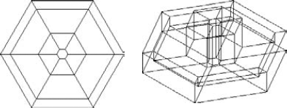
Your basic point of reference is plan view in the World Coordinate System (WCS). This is the view that you use in 2D, so it's familiar. Plan view is the view from the top (although which side is the top is not always obvious). Figure 22.1 shows a plan view of a 3D model on the left. On the right, you see a 3D view of the same model, which lets you visualize the three dimensions much more clearly.
When working in 3D, you can use many of the familiar 2D techniques for viewing your drawing:
Use ZOOM Previous to display the previous viewpoint.
Save views so that you can easily return to them.
Use real-time zoom and pan as well as all the other zoom options.
Create tiled viewports to display more than one view at a time.
Note
You can save drawings in the 3D DWF format (in AutoCAD only) for viewing on the Web or sending to people. For more information, see Chapter 28.
This chapter also explains how to save 3D views, create presentations from saved views, walk through a 3D model, create visual styles that control how your models look, lay out 3D drawings for plotting, and print in 3D.
AutoCAD and AutoCAD LT offer 10 standard viewpoints. These viewpoints are useful — and easy to use. They are relative only to the World Coordinate System (WCS), not the current User Coordinate System (UCS). Therefore, they're most useful when you're using the WCS.
To use a preset viewpoint, choose View tab
The VPOINT command was the original, command-line method of setting viewpoints. Now it's generally used for scripts and AutoLISP routines when you need a way to set a viewpoint from the command line. (AutoCAD LT does not support AutoLISP routines.)
The VPOINT command defines a viewpoint using X, Y, and Z vectors. The vectors for the standard viewpoints are based on a maximum of 1 unit. Imagine a model of the three axes floating out in space. You're a superhero and can fly around the model from any angle. When you're over the Z axis, you can define the Z vector from 0,0,0 to your position as 1. The other vectors are 0 (zero) because you're right over them, so that 0,0,1 defines the top, or plan, view. The next section shows the vector equivalents for the standard viewpoints, to give you a feel for the vector system. I explain the VPOINT command's compass and tripod later in this chapter.
Showing the viewpoints is easier than describing them. In Table 22.1, I show a simple 3D house from all ten standard viewpoints. Although the front of the house faces east, this is particular to this house. From your drawing's point of view, east is 0 degrees when looking from the top view, and 0 degrees faces to the right.
Note
A system variable, UCSORTHO, automatically changes the UCS to match the viewpoint when you switch to one of the orthographic (top, bottom, left, right, front, and back) viewpoints. In order to distinguish between the viewpoints and UCSs, I turned UCSORTHO off for the following section.
Note
You can also access the top view by typing plan on the command line. Note that the PLAN command does not change the UCS, even though you choose to see the plan view of a different UCS. This actually makes it very flexible because you can see what your drawing looks like from a different UCS without actually changing the UCS. The PLAN command is explained later in this chapter.
Note that the terms Northeast, Southwest, and so on are not related to any real directions. However, you can specify a North direction for your model. You would generally do this in an architectural or civil engineering drawing. To do so, choose Render tab
You can then choose to specify the geographic information by importing a KML or KMZ file, by importing information from Google Earth, or by manually entering location values. KML and KMZ files are Google Earth file formats. For the Google Earth option to work, you need to install Google Earth (at 0). If you choose to enter location values, the Geographic Location dialog box opens. Here you can enter latitude and longitude measurements manually, or use a map. You specify which hemisphere (North/South and East/West) you're in. You can also set the time zone, North direction, and up direction (Z axis), and specify an elevation for a specific coordinate.
If you start the GEOGRAPHICLOCATION command in a drawing that already has a location, you get a choice to edit the current location, redefine it (start from scratch), or remove it.
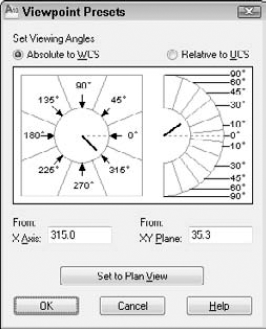
If the standard views aren't sufficient for your needs, DDVPOINT can give you both flexibility and precision. To use this command, enter ddvpoint
The left side of the dialog box determines the angle from the X axis in the XY plane. These angles work as follows:
270Front view
0      Right view
90     Back view
180    Left view
Other angles result in viewpoints between these views. For example, an angle of 315 degrees enables you to look at your drawing from a view between front and right. This is similar to the SE isometric view.
The right side of the dialog box determines the angle from the XY plane, in the Z direction. A 0-degree angle enables you to look at your drawing from the front, back, or one side (elevation views), depending on the setting on the left part of the dialog box. Often you want to look at your drawing from above. A 90-degree angle shows you the plan view. An angle between 0 and 90 gives you a slanted view from the top, such as for one of the isometric standard views. (The isometric views set the angle from the XY plane to 35.3 degrees.)
Tip
There's an art to using the two dials to set the view angle that you want. If you click the inside border of either one, close to the indicator needle, you set the angle based on exactly where you clicked. This results in uneven degrees, such as 47.6. However, if you click the outside border of either image, or the numbers themselves, the angle is rounded to the value in the segment.
When you open the dialog box, the black needles indicate the angles for the current view. When you change the angles, the black (or white) needles move to the new angle, but the original needle remains to indicate the current angle. This enables you to constantly see the current angles for reference.
Beneath the dials are text boxes that reflect your choices. You can simply type the angles that you want in the text boxes.
A very handy Set to Plan View button is at the bottom of the dialog box. This enables you to quickly return to plan view when you become a little dizzy from flying around your model.
The default is to view the drawing based on the WCS. However, sometimes you need to see your drawing relative to a UCS that you've created. To do so, click Relative to UCS.
Tip
Keep the number of UCSs to the minimum necessary and save them. When possible, use a new viewpoint instead of creating a new UCS. The Dynamic UCS feature (available in AutoCAD only) creates temporary UCSs; I discuss this feature in Chapter 21.
Click OK after you finish making your changes.
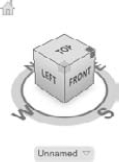
The ViewCube is a quick, visual way to switch your viewpoint. You can think of the preset viewpoints as sides, edges, or corners of a cube. The ViewCube is semitransparent until you hover the cursor over it. To display a viewpoint, you click the side, edge, or corner that you want. You can also drag the ViewCube to interactively change your viewpoint. In this way, you can easily make small adjustments as you work. This is very similar to using 3D Orbit, which I discuss later in this chapter. Figure 22.3 shows the ViewCube.
The ViewCube has four additional features:
UCS menu. Below the ViewCube is a list of saved and default UCSs. You can switch UCSs and create a new UCS.
Compass. You see the four directions marked around the ViewCube. The directions are based on the settings for the GEOGRAPHICLOCATION command, discussed earlier in this chapter. You can click one of the directions, or the arrow next to it, to view the model from that direction.
Home. Click the Home button at the top-left corner to display the model at its default viewpoint, which is either the extents of the drawing (for preexisting models), or a top/left/front view. You can specify the definition of the Home view. To do so, set the view the way you want it, right-click the ViewCube, and choose Set Current View as Home.
Context menu. Click the small button to the right of the UCS menu for more settings and options.
You can right-click the ViewCube and choose the type of projection: parallel or perspective. I discuss these projections later in this chapter.
Choose View tab
Specify in which corner of the screen the ViewCube appears
Set the ViewCube size
Set the ViewCube opacity when inactive
Display or hide the UCS menu
Snap to the closest view when dragging. If you want to make small adjustments by dragging, uncheck this check box.
Zoom to extents after a view change
Use view transitions when switching views to create a smooth, animated change
Orient ViewCube to the current UCS
Keep the scene upright
Show or hide the compass
Restore default settings
Note
The ViewCube doesn't display in the 2D Wireframe visual style. If you don't see the ViewCube, change the visual style to 3D Wireframe (or any other visual style other than 2D Wireframe). Choose Home tab
Compare the ViewCube with the 3D Orbit feature, covered later in this chapter. Then you can choose the feature that will provide you with better control or quicker results.
A camera is a way to define and save a 3D view. When you save a named view by using the VIEW command, you display the view that you want and then save it. When you use a camera, you define a location and a target to define the view. AutoCAD places a camera glyph (visual representation) in the drawing to represent the view. You can select the camera glyph and edit its properties by using its grips. You can also edit the camera's properties in the Properties palette. By default, the camera glyph does not plot. Cameras are listed in the View Manager dialog box, along with other named views.
Note
The CAMERA command is not available in AutoCAD LT. When you open an AutoCAD drawing containing a camera in AutoCAD LT, the camera glyph doesn't appear.
Note
The Camera panel is not displayed by default. To display it, right-click any blank area on the Render tab and choose Panels
The next prompt offers the following options:
?. Displays the
Enter camera name(s) to list <*>:prompt. Press Enter to list all current camera names and other named views in the drawing.Name. Lets you name the camera. If you don't use this option, the command assigns a default camera name, starting with Camera1 and so on.
LOcation. Use this option to change the camera location.
Height. Sets the camera height. You can use this to change the Z value of the camera after specifying its location on the XY plane.
Target. Use this option to change the camera's target.
LEns. Defines the field (width) of view in degrees, using a camera lens length in millimeters. Table 22.2 describes the relationship between lens length and field of view.
Clipping. Creates front and back clipping planes for the view.
View. You can use this option to make the camera's view current. Use the Yes suboption. This ends the command.
eXit. Exits the command.
You can also create a camera from the tools palette. Display the Cameras tool palette tab. Choose one of the three cameras (Normal, Wide-angle, or Extreme Wide-angle) and drag it onto the drawing area. Release the mouse button. Then click to place the camera and click again to specify the target.
When you create the camera, you can set its view to current by using the View option. After you change the view, you can get back to the view by choosing it in the View Manager and setting it to current. You can also select the camera, right-click, and choose Set Camera View.
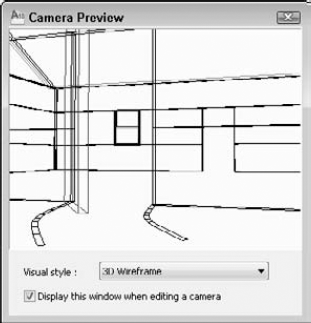
When you edit a camera, the Camera Preview window opens to show you a preview of the camera's view, as shown in Figure 22.4. You can change the visual style within the Camera Preview window, using the Visual Style drop-down list. (This doesn't change the visual style in the main drawing area.)
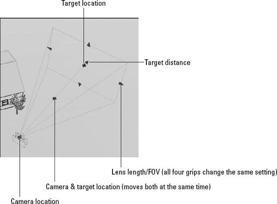
To edit a camera, select it and use its grips to change the camera location, target location, and lens length (field of view), as shown in Figure 22.5. Each grip has a tooltip to tell you its purpose. When you select a grip to make it hot, you can enter a new coordinate in the Dynamic Input tooltip. You can also edit the properties of a selected camera in the Properties palette.
Note
The drawing used in the following exercise on using standard viewpoints, CAMERA, the ViewCube, and DDVPOINT, ab22-a.dwg, is in the Drawings folder on the DVD.
STEPS: Using Standard Viewpoints, CAMERA, the ViewCube, and DDVPOINT
Open
ab22-a.dwgfrom the DVD.Save it as
ab22-01.dwgin yourAutoCAD Biblefolder. It shows the same house used in Table 22.1, from the SE isometric view.Type ucsortho


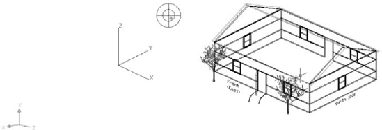
If you have AutoCAD, click the bottom-right corner of the ViewCube's central square. Because this corner is between the South and East directions, as shown by the compass, you now see the SE Isometric view.
Click Top in the ViewCube to see the top of the house.
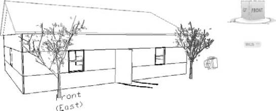
To see the front view of the house, click the S in the compass, or the arrow just above the S.

Current camera settings: Height=0″ Lens Length=50.0000 mm Specify camera location:
27',-15'Specify target location:15',20'Enter an option [?/Name/LOcation/Height/Target/LEns/Clipping/View/ eXit]<eXit>:nEnter name for new camera <Camera1>:thruFrontDoorEnter an option [?/Name/LOcation/Height/Target/LEns/Clipping/View/ eXit]<eXit>:hSpecify camera height <14'>:5'Enter an option [?/Name/LOcation/Height/Target/LEns/Clipping/View/ eXit]<eXit>:leSpecify lens length in mm <35.0000>:28Enter an option [?/Name/LOcation/Height/Target/LEns/Clipping/View/ eXit]<eXit>:vSwitch to camera view? [Yes/No] <No>:yType ddvpoint
Repeat the DDVPOINT command. In the X Axis text box, type 240. In the XY Plane text box, type 5. Click OK. You view the house from slightly off the ground, much as you might see it if you were walking up to the house.
If you have AutoCAD, choose Home tab

Choose Home tab
If you're working on someone else's computer or want UCSORTHO on, type ucsortho
Save the drawing.
Note
In AutoCAD, when you save the view, by default you save it with the current visual style. Therefore, if you change the visual style and restore the view, the visual style changes back to the one you used when you saved the view. If you don't want to save the visual style, choose <None> from the Visual Style drop-down list in the New View/Shot Properties dialog box.
When you save a named view by using the View Manager, you can add a background. I discussed the View Manager in Chapter 8, but here I explain how to add a background. Backgrounds only apply to 3D views. They are not available in AutoCAD LT.
You can add a solid, gradient, or image background to a named view. Whenever you display that view, the background appears if the current visual style has backgrounds turned on (the VSBACKGROUNDS system variable). Backgrounds, especially image backgrounds, are usually used in the context of rendering, and I include an exercise on adding a background in Chapter 25.
To create a view with a background, choose View tab
Note
You can specify lighting in real-world units. To turn on this feature, you set the LIGHTINGUNITS system variable to 1 or 2. By default, this feature is on (set to 2). When photometry is on, you have an additional background option, Sun & Sky. If you choose this option, the Adjust Sun & Sky Background dialog box opens. The settings in this dialog box are the same for creating sunlight when photometry is on. I explain this feature, called photometry, in Chapter 25 where I discuss lights.
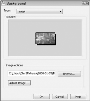
The Background dialog box opens, shown in Figure 22.7, after choosing the Image option and clicking Browse to choose an image file.
In the Background dialog box, you again have the opportunity to choose one of three options. To specify the background, choose one of the following:
Solid background. Choose Solid (the default) from the Type drop-down list. Click the color swatch in the Color section. In the Select Color dialog box that opens, choose a color.
Gradient background. Choose Gradient from the Type drop-down list. For a two-color gradient, uncheck the Three Color check box. Click in each color swatch to open the Select Color dialog box and choose a color. To rotate the gradient, enter a rotation angle in the Rotation text box or use the arrows to change the value.
Image background. Choose Image from the Type drop-down list. Click the Browse button to choose an image file (in BMP, JPEG, TIF, PNG, TGA, GIF, or PCX format), and click Open. To adjust the position, scale, or offset of the image, click the Adjust Image button. In the Adjust Image dialog box, you can choose a position (Center, Stretch, or Tile) to specify how the image fits the viewport. You can also click the Offset or Scale option button and use the sliders to change the offset or scale of the image. Click OK when you're done. You can see an example of an image background near the end of Chapter 25.
When you specify the background, click OK to return to the View Manager, and click OK again to return to your drawing.
To edit a background, choose the view from the View Manager, click the Background item in the General category, click the down arrow, and choose Edit. You can also choose <None> to remove the image.
Note
The New View/Shot Properties dialog box lets you define shot properties. I discuss shot properties and the related ShowMotion feature later in this chapter.
The VPOINT command offers another method of defining views, the tripod and compass. Note that this method is rarely used nowadays, because other viewing tools are more efficient. To start this command, enter vpoint
If you type the VPOINT command, or press Enter to repeat the command, press Enter at the Current view direction: VIEWDIR=−1.0000,−1.0000,1.0000 Specify a view point or [Rotate] <display compass and tripod>: prompt to see the compass and tripod. (The numbers show the current viewpoint.)
Move the cursor about, and two things happen. The cursor moves within the compass, and the axes dynamically shift position.
Imagine that you take a tangerine and make a large, cross-shaped cut at the very bottom. Then you open out the bottom and remove the peel from the tangerine. Flatten the peel on the table. This is the concept of the compass, except that the outer edge is round. (The tangerine peel would have the shape of the cuts on its outer edge.) The very center of the compass — or the peel — is like the North Pole. When you're over the North Pole, you're looking straight down at your model — or the tangerine. This produces a plan view. The inner circle of the compass is where the middle of the tangerine was, at the equator. From the equator, you're looking sideways (from the front, back, or side) at your model. The outer circle of the compass represents the South Pole. From over the South Pole, you're looking at the bottom of your model — or the tangerine.
All of this determines your view relative to the XY plane:
At the center of the compass, you're right on top, looking down. This is a plan view.
At the inner circle, you're on the side, looking at the XY plane on its edge.
At the outer circle, you're beneath the XY plane, looking up.
The cross that goes through the compass represents the X and Y axes. To summarize, going clockwise:
The positive X axis gives you a right view.
The negative Y axis is equivalent to a front view.
The negative X axis gives you a left view.
The positive Y axis gives you a back view.
When you have the cursor at the desired location, simply click. Your drawing displays the viewpoint that you specified.
Along with the tripod and compass, you see the current UCS icon based on the current UCS to help you find your bearings. Figure 22.8 shows, on the left, the cursor location that results in the viewpoint shown on the right. This is very close to the SE isometric view.
The PLAN command is a quick way to return to plan view. Type plan
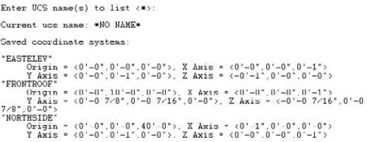
Figure 22.9 shows a sample UCS listing. The units are architectural.
Note
The Express Tools' extended PLAN command, EXPLAN, prompts you to select objects so that you can see the plan view zoomed in on those objects. Choose Express Tools tab
You may have noticed when you open AutoCAD with the default 3D environment that the grid lines look like they're receding into the distance. That's because AutoCAD is displaying a perspective view, which makes parallel lines converge as they get farther away. Because this is how parallel lines look in real life (try looking down a road into the distance), a perspective view looks more realistic than a parallel view that keeps lines parallel, regardless of their distance. However, when you zoom in, objects may appear distorted. Use a perspective view when you want to convey a realistic sense of depth. In general, perspective view is most useful in architectural settings. AutoCAD LT doesn't include perspective projections. The PERSPECTIVE system variable controls the current view. A value of 0 turns off perspective view; 1 turns it on.
The 3D Orbit feature is a fully interactive way to change your viewpoint in real-time. Using 3D Orbit is like orbiting the earth to view any continent or ocean below. When you enter 3D Orbit mode, you cannot use other commands. In this regard, 3D Orbit is like Realtime Pan and Realtime Zoom. Similarly, you can press Esc or Enter to exit 3D Orbit mode. You access the 3D Orbit options by right-clicking in the drawing area to display the 3D Orbit shortcut menu.
Note
3D Orbit is not available in AutoCAD LT. This entire section, including the exercise, is for AutoCAD only.
Use 3D Orbit for fine control over the viewpoint. To quickly change the viewpoint to one of the preset views, you can use the ViewCube, covered earlier in this chapter. (You can also drag the ViewCube, which then functions similarly to 3D Orbit.)
Tip
You can use 3D Orbit transparently, that is, in the middle of another command. Just press and hold Shift and your mouse's wheel (using it like a button), rotate your model as you want, and release the buttons. You then continue the command in progress. This way of using the 3DORBIT command without actually executing the command makes it very easy to navigate your model. You can also use 3D Orbit in the Block Editor when editing 3D blocks.
The 3D Orbit mode includes the ability to zoom and pan. Therefore, you can use this command for more than just orbiting.
The default 3D Orbit mode is Constrained Orbit. Drag to the left or right to rotate the model around on the XY plane, and drag up or down to rotate the model along the Z axis. You can't rotate the model upside down in Constrained Orbit mode. Drag diagonally to create isometric views.
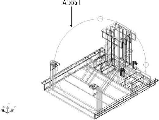
Free Orbit mode displays an arcball and has four cursors that affect how your model rotates. Each cursor is location based. As you move your cursor to a new location, the cursor shape changes, and the type of rotation changes. The arcball is shown in Figure 22.11.
You use the arcball in the following ways:
3D Orbit includes three visual aids that can help you find your bearings:
Compass. Displays a sphere that is made up of three dashed lines labeled as the X, Y, and Z axes. The lines look like the threads of a baseball.
Grid. Displays a grid of lines representing the XY plane. The Z coordinate of the grid is equal to the value of the ELEVATION system variable, which is set to 0 (zero) by default. You can specify the structure of the grid with the GRIDUNIT system variable. You can set this value by right-clicking the Grid Display button on the status bar and choosing Settings before you use this visual aid.
UCS icon. Displays a shaded, three-dimensional 3D UCS icon. The X axis is red, the Y axis is green, and the Z axis is blue.
You would rarely want to use all three visual aids. The compass and grid can both interfere with viewing your model, so use them temporarily when needed.
To display the visual aids, right-click while in 3D Orbit mode and choose Visual Aids from the shortcut menu. Then choose the aid that you want from the submenu. To turn off the visual aids, follow the same procedure — the submenu items toggle the visual aids on and off when you click them.
Note
If you choose a visual style (other than the default 2D wireframe), the visual aids remain active after you exit 3D Orbit. You can switch to the 2D wireframe visual style, as explained earlier in this chapter, or you can re-enter 3D Orbit and turn off the visual aids.
Absolutely the coolest feature of 3D Orbit — and one of the coolest features of AutoCAD as a whole — is continuous orbit. Continuous orbit enables you to choose a direction of rotation and then let go. 3D Orbit automatically continues the rotation in the same direction and continues it until you change or stop it. With continuous orbit, who needs screensavers? Here's how it works:

Click and drag in the direction of rotation that you want to create. The faster you drag, the faster the resulting orbit.
Release your mouse button. Your model continues to rotate in the same direction. All you do is watch.
Continuous orbit is an ideal way to view your model. As your model rotates, you can pick out any errors and then stop continuous orbit to fix them. You can change the direction of your continuous orbit at any time by clicking and dragging in a new direction and then releasing the mouse button. To stop continuous orbit, choose any other 3D Orbit mode or click in the drawing window.
3D Orbit offers many options for refining your view so that you see just the view that you want. You can pan and zoom, adjust the camera distance, create parallel and perspective views, set clipping planes, or display a preset view. You can also start Walk or Fly mode, as discussed later in this chapter.
Because you cannot use other commands while in 3D Orbit mode, you access most of these options by right-clicking in the drawing area to access the 3D Orbit shortcut menu.
To zoom to a window in 3D Orbit, right-click and choose Zoom Window from the shortcut menu. Your cursor displays a small rectangle. Click and drag, and then release the mouse button to define the two corners of the window.
To zoom to drawing extents in 3D Orbit, right-click and choose Zoom Extents. To return to the previous view, right-click and choose Zoom Previous.
You can adjust the distance between the viewer, called the camera, and the target, which by default is set to the center of the 3D view (this view may be different from the center of your model). Changing this camera distance is equivalent to zooming in and out.
To adjust the camera distance in 3D Orbit, right-click and choose Other Navigation Modes
When you use 3D Orbit, the Properties palette displays special properties that relate to 3D Orbit features, as follows:
View Height is a way to specify the distance of the imaginary camera. In other words, you can use this property to zoom in and out on your model. A larger number makes your model look smaller because the distance (or height) of the camera from the model increases.
View Width is another way to zoom in and out. Here you specify the width of the view of the imaginary camera. A larger number makes your model look smaller because the view encompasses a larger area (and your model is a smaller part of that area).
Lens Length and Field of View define the angle of the view. I discuss these concepts in the section "Creating a Named View with a Camera" earlier in this chapter.
To change one of these properties, click its row in the Properties palette. Type a new value and press Enter.
To create a perspective view in 3D Orbit, right-click and choose Perspective. To return to parallel view, choose Parallel. For more information on perspective views, see the section "Displaying Parallel and Perspective Projections" earlier in this chapter.
After you use 3D Orbit a few times, your model may appear askew, with no indication of how to return it to a viewpoint that you can comprehend. You can switch to any of the preset views discussed at the beginning of this chapter. From 3D Orbit, right-click and choose Preset Views from the shortcut menu. Then choose one of the standard viewpoints on the submenu list.
Note
The drawing used in the following exercise on working in 3D Orbit, ab22-b.dwg, is in the Drawings folder on the DVD.
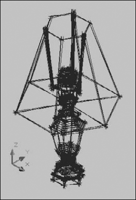
Open
ab22-b.dwgfrom the DVD. This is a 3D chair shown from a Northeast isometric view.
Place the mouse cursor to the right of the chair in the middle (vertically) of the screen. Drag to the left twice until the chair turns around completely and is back to approximately its original position.
Place the cursor below the chair and drag up until it stops. Drag down until the chair is in its original position. Place the cursor above the chair and drag down until it stops. Return the chair to its original position again.
Place the cursor above the chair until you are looking down at it — a Top view. The chair is still rotated. Drag from the left to the right until the chair's bottom is horizontal on the screen.
Right-click and choose Other Navigation Modes
Right-click and choose Zoom Previous to return to the Top view.
Type 1 to return to Constrained Orbit mode. The arcball disappears.
Right-click and choose Other Navigation Modes
Type 1 to stop the continuous orbit.
Right-click and choose Reset View to re-display the chair exactly in its original view.
Type 9 (pan). Pan the chair to the right a little.
Right-click and choose Other Navigation Modes
Right-click and choose Preset Views
Press Esc to exit 3D Orbit mode.
Don't save your drawing.
To show a drawing to others, or better visualize multiple angles of a model, you can create named views called shots, and then use the ShowMotion feature to display them one after another as a presentation. You can add motion and animation to your shots.
Note
The ShowMotion feature is not available in AutoCAD LT.
In the View Name text box, enter a name for the shot. You can create view categories, which are groups of shots. Use categories to help you organize many shots into sections. To create a view category, enter a name in the View Category text box. After you create a view category, you can choose it for subsequent shots from the View Category drop-down list.
From the View Type drop-down list, you can create three types of shots:
Still. A single camera position (For more information on cameras, see "Creating a Named View with a Camera" earlier in this chapter.)
Cinematic. A single camera position, plus camera movement
Recorded Walk. Animation along a path
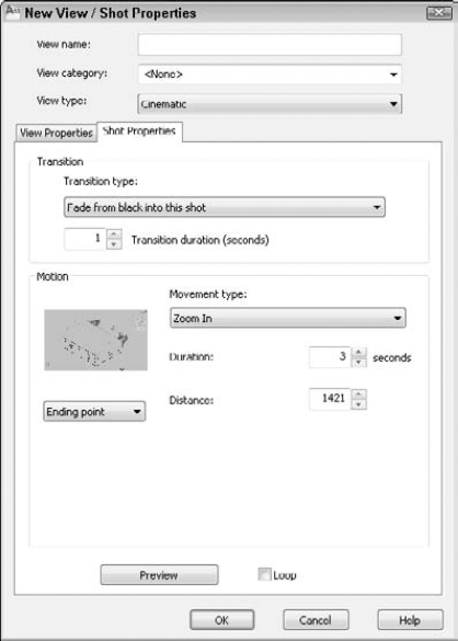
Figure 22.12. Use the Shot Properties tab of the New View/Shot Properties dialog box to specify the properties of a shot.
In the Transition section, choose a transition type from the drop-down list. The transition occurs between the display of the previous shot and the current shot that you are defining. You have three choices:
Fade from black into this shot. Creates a fade transition to the shot from a black screen. Use this option when you want the fade effect and have a black background.
Fade from white into this shot. Creates a fade transition to the shot from a white screen. Use this option when you want the fade effect and have a white background.
Cut to shot. Immediately switches to the new shot.
Then choose the duration of the transition in seconds by entering a value or clicking the up or down arrow.
The bottom part of the dialog box changes, depending on the view type. For a still shot, you simply choose the duration, in seconds. For a cinematic shot, you start by choosing one of eight movement types. For example, you can zoom in or out. For a recorded walk, you return to your drawing and drag in the direction of the walk. Release the mouse button to stop recording. (See the section "Walking through a Model" for another way to record a walk through your drawing.) You can preview the results by clicking the Preview button. You can also loop the entire presentation by clicking the Loop check box at the bottom. When you're done, click OK.
Continue to create new shots until you have the ones that you want. To modify any shot, right-click its thumbnail and choose Properties. Make your changes in the dialog box and click OK.
To display the shots in order, use the ShowMotion feature. Choose ShowMotion on the status bar to display the ShowMotion toolbar at the bottom of your screen, as shown in Figure 22.13.
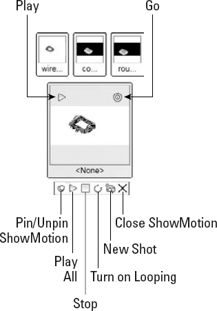
The ShowMotion feature displays two levels of thumbnails. The bottom level shows either the first of a set of shots or the first view in a view category. The upper level shows all the shots, organized by view categories, if any. As you pass your cursor over a thumbnail, it enlarges. When you hover the cursor over each thumbnail, two buttons appear — one to play or display the shot or view category, and the other to go to the beginning of that shot or view category.
The ShowMotion toolbar contains buttons that enable you to pin or unpin the ShowMotion interface, play the entire set of shots, stop the display, loop the display, create a new shot, and close the interface.
When you click the Play button on either a thumbnail or the toolbar, it becomes a Pause button that you can click to pause the display.
To better see what a model looks like, and to show it to clients, you can "walk" through it. This feature is most useful for architectural models, because it simulates walking through a space, such as a building. Although Walk appears as a mode on the 3D Orbit shortcut menu, it has its own unique navigational system. Walking maintains your view parallel to the XY plane, but you can use the Fly mode to move away from the XY plane.
You can record your walk-through and save it as an animation file to play back later. In addition, you can create an object that functions as a motion guide, called a motion point or path. You can then record an animation file that uses the point or path to define the walk-through.
Note
AutoCAD LT doesn't include walk- or fly-throughs, nor does it include any way to create a movie file of your drawing navigation.
You must be in perspective view to use Walk and Fly modes. If you aren't, a message asks you whether you want to toggle to a perspective view.
By default, you see a translucent box in the upper-right corner of the screen, providing the instruction to use the keyboard to navigate, and the mouse to look around and turn. (If you don't see the box, press the Tab key.) Move the cursor over the box to make it opaque, and click its down arrow to expand the box and show navigation instructions, as follows:
Up arrow/W key. Move forward
Down arrow/S key. Move backward
Left arrow/A key. Move left
Right arrow/D key. Move right
Drag mouse. Look around and turn
F key. Toggle Fly mode (which lets you leave the XY plane)
Tip
Because walking through a model is sometimes a little cumbersome, depending on the capabilities of your graphics card and the complexity and size of your model, you should display your desired starting point before you enter 3DWALK. Also, switch to the visual style you want to use before entering Walk mode; otherwise, right-click and choose Visual Styles.
Because you turn by dragging with the mouse, you'll probably find it easiest to use the W, A, S, and D keys with your left hand (assuming you use your right hand for your mouse). This set of keys is used for navigating in computer games and provides an easy way to move in the four directions without looking at the keys.
When you start the 3DWALK command, the Position Locator window opens, and your cursor changes to a plus sign, as shown in Figure 22.14. The Position Locator window shows you your model from the top so you can gauge your position.
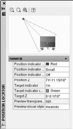
A helpful feature of the Position Locator is that you can drag the red dot that represents your position to move your current position. You can also drag the target indicator to change your view. In the General section of the Position Locator window, you can also specify the following settings:
Position indicator color. Changes the color (which is red by default) to contrast better with your model.
Position indicator size. Changes the indicator's size to small, medium, or large.
Position indicator blink. Makes the indicator blink, if you want.
Position Z. Sets the Z coordinate for the current position.
Target indicator. Turns the target indicator on or off. Having it on is generally helpful because it explains what you are seeing in the main drawing area and you can drag it to change your view.
Target indicator color. Changes the color (which is green by default) to contrast better with your model.
Preview transparency. Sets the transparency of the preview in the Position Locator window. For example, if you're in a house, shown in Figure 22.15, you want to be able to see through the roof. You can set a number from 0 to 95. Don't include the percent (%) symbol when you enter a new number.
Preview visual style. Specifies a visual style for the preview.
When you're ready to walk, press the W or Up Arrow key. You can press the key repeatedly or hold it down, but if you hold it down for a while, you may need to wait for the display to catch up. As you walk, you can drag to the left or right to change your direction. You can also drag up or down. Whenever you need to get your bearing, just look over at the Position Locator window to see where you are as well as your view's target.
Note
The capabilities of your computer, including your graphics card, have a major effect on the performance when you walk through a model. AutoCAD needs to make many calculations each second to re-display your screen as you change position.
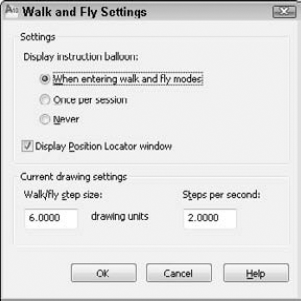
You can choose when the instruction window displays. After a while, you know the instructions, so you probably don't want the window to display each time you enter Walk or Fly mode. You can also choose whether or not to display the Position Locator window.
To change the size of your steps and how many steps you move per second, use the settings in the Current Drawing Settings section. If you set your steps too small, walking seems too slow, but if they're too big, you don't have as much control. Click OK when you're done changing the settings.
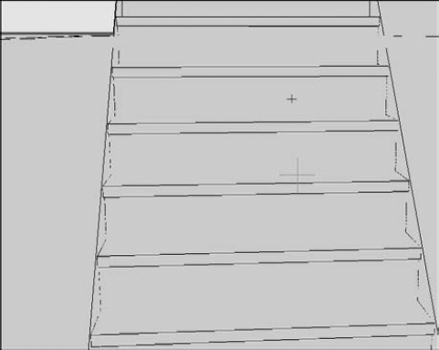
Walking through a model keeps you parallel to the XY plane. However, sometimes you may want to look at the roof of a house or go up some stairs. Fly mode frees you to leave the XY plane.
The controls are the same for Fly and Walk modes, except that when you drag the mouse forward in Fly mode, you go upward, away from the XY plane, and when you drag the mouse backward (toward you), you go downward. Figure 22.16 shows the process of "flying" up a flight of stairs.
You can record your walk- or fly-through as you go, and save the result as a movie (video) file. If you want, you can specify the movie settings before you start by entering 3D Orbit mode, right-clicking, and choosing Animation Settings. The Animation Settings dialog box opens, as shown in Figure 22.17.
In the Animation Settings dialog box, you can choose a visual style or presentation quality from the Visual Style drop-down list. Choose a resolution from the Resolution drop-down list. The Frame Rate (FPS) option determines the number of frames per second. Finally, choose one of the four available movie formats from the Format drop-down list: AVI, MOV, MPG, or WMV (the default). Note that the first three settings greatly affect the size of the resulting movie. When you're done, click OK.
Note
To save to the MOV format, you need to install Apple QuickTime Player. You need Microsoft® Windows Media Player® 9 or later installed to save to WMV format; if it isn't installed, AVI is the default format.
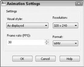
Figure 22.17. The Animation Settings dialog box specifies settings for a move that you record during Walk or Fly mode.
Tip
You can drag in the Position Locator while you're recording to move your current position, change your target position, or turn around.
When you click the Save Animation button, the Save As dialog box opens, where you can save the movie. Navigate to the desired location, enter a name, and click Save. At this time, you can click the Animation Settings button and change the animation settings. The Creating Video progress meter displays to show you the progress as the movie saves. When it's done, open the movie file and watch. Bring some popcorn!
Tip
If you don't like the result, press Esc to end the 3DWALK command, and choose View tab
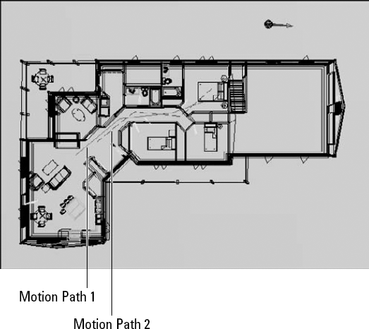
Using Walk and Fly modes can result in some jerkiness as you make little adjustments along the way. For a smoother ride, you can draw a motion path and save a movie file that automatically runs along the path.
You need to specify both the camera and its target. They can be either a point or a path (line, arc, elliptical arc, ellipse, circle, polyline, 3D polyline, or spline), but they can't both be a point. For example:
If the camera is a point and the target is a circle, the resulting movie is like standing in one place and turning around.
If the camera is a circle and the target is a point, the result is like walking around a point (such as the center of a table) that you look at throughout.
The first step is to create one or two motion paths for the camera and/or the target. If you are using paths, a polyline is ideal if you want to add some turns, because you can only select one object for each motion path.
Tip
You may want to create a separate layer that you can later turn off. Also, you usually want to place the height of the motion paths at eye level. You can place the camera and target paths at different heights, or use a 3D polyline and vary the heights along the way.
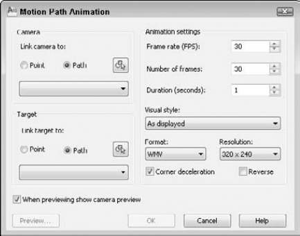
Figure 22.18. Specify the motion paths and movie settings before you create a motion path animation.
Follow these steps to set up the motion path animation:
In the Camera section, choose either Point or Path. If you choose Path, name the path or accept the default name. Then click the Select Path or Pick Point button to select an object for a motion path or to specify a point.
In the Target section, do the same. Remember that you can't choose a point for both the camera and the target.
In the Animation Settings section, set the frame rate in frames per second and set the number of frames. The Duration adjusts automatically, based on your choices.
Choose a visual style from the Visual Style drop-down list.
Choose a format and resolution. These settings are the same as for a walk-through animation, which I discussed in the previous section of this chapter.
By default, the movie slows down around corners. You can uncheck the Corner Deceleration check box if you want to. You can also check the Reverse check box to make the animation go backward.
Click the Preview button to preview the result. Remember that the preview may not be as good as the final movie. In my experience, the preview did not use the visual style I chose, but the final did. Close the Preview box.
Click OK.
In the Save As dialog box, navigate to the desired location. Enter a name and click Save. You can click the Animation Settings dialog box to change the settings before you save. The Creating Video progress meter shows your progress, and the Preview Animation window previews the animation.
Note
The drawing used in the following exercise on using Walk mode and creating animations, ab22-c.dwg, is in the Drawings folder on the DVD.
STEPS: Using Walk Mode and Creating Animations
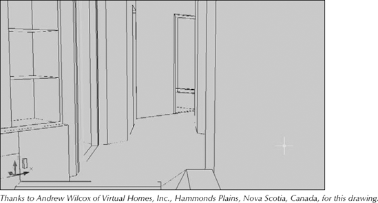
Open
ab22-c.dwgfrom the DVD.Save the drawing as
ab22-02.dwgin yourAutoCAD Biblefolder. You're inside a 3D house, looking down a hallway, in the 3D Hidden visual style, as shown in Figure 22.19. Type ucsortho

Press and hold the W key, or press the W key multiple times until the Position Locator indicates that you're in the narrow hallway. If necessary, let the screen re-display the model.
Continue to walk to the end of the diagonal segment of hallway, as shown in the Position Locator. If necessary, drag slightly to the left or right with your mouse to adjust your view. Don't mind that along the way you may be seeing through walls.
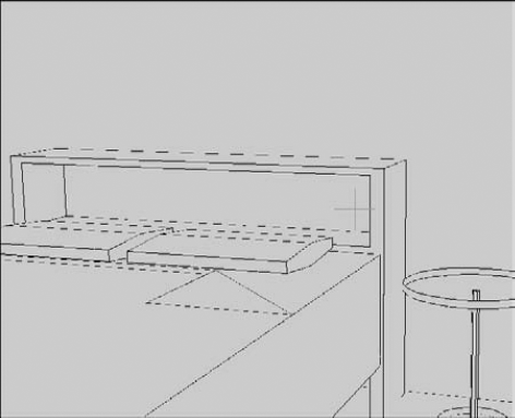
With your mouse, drag to the right to turn to the right, until the Position Locator shows the center target line horizontal, facing right. You should be able to see the table inside the bedroom, through a partially open door. You might need to drag upward.
At this point, you'll record the rest of your walk as a video file. Right-click and choose Animation Settings. Change the Visual Style to 3D Hidden and change the Frame Rate (FPS) to 15. Choose WMV or AVI as the format, depending on what you think you can play on your computer (probably either). Click OK.

Continue to walk forward using the W key and dragging slightly to the left to keep the bed in the bedroom in the center of your view until your screen looks like Figure 22.20.
Click Render tab

In Windows Explorer, double-click the file to open it and watch the animation.
Now you want to create an animation from a motion path. Type plan

Double-click the movie file in Windows Explorer to view it.
Save your drawing.
Note
You can find ab22-02a.wmv and ab22-02b.wmv in the Results folder of the DVD.
The SteeringWheel, or wheel for short, is a navigation and viewing tool that combines several features in one place. The wheel appears at your cursor and comes in several variations, as shown in Figure 22.22.
Note
The 2D Navigation and AutoCAD LT wheel doesn't offer any variations or settings. I cover the SteeringWheel for 2D navigation in Chapter 8. Here I explain the 3D navigation features, which are available in AutoCAD only.
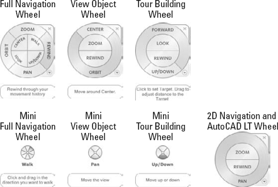
Figure 22.22. The SteeringWheel has several variations, all of which help you navigate and view your drawing.
To use any wheel, you place the cursor over the desired tool on the wheel, then click and drag. Each tool is in a section called a wedge. The default wheel in AutoCAD is shown at the top left in Figure 22.22 and includes the following tools:
Zoom. Performs a real-time zoom.
Rewind. Displays previous views in thumbnails. You can revert to any previous view by clicking its thumbnail.
Pan. Pans the view.
Orbit. Functions like the 3D Orbit feature, orbiting around a pivot point.
Center. Defines the pivot point for orbiting. Press Ctrl as you zoom (or use the View Objects wheel) to provide a center point for zooming.
Walk. Lets you walk through your drawing.
Look. Swivels the view.
Up.Down. Moves the view along the Z axis, like going up or down in an elevator. You drag along a Top-Bottom slider.
As you can see in Figure 22.22, the View Object and Tour Building wheels contain subsets of the tools in the default wheel. The mini wheels provide the same tools as their full counterparts, but they are smaller and don't contain the full labeling. All the wheels provide tooltips and brief instructional messages when you hover the cursor over a wedge.
To specify settings for the wheel (AutoCAD only), right-click it and choose SteeringWheel Settings to open the SteeringWheel Settings dialog box, where you can do the following:
When you're done with the wheel, press Esc or Enter. You can also click the wheel's X button (for the full-size version), or right-click and choose Close Wheel.
The original command for defining views with perspective from any angle and distance was DVIEW. The newer 3D Orbit feature is easier to use than DVIEW, but you may still find DVIEW helpful for its precise ways of defining a view. DVIEW is also useful if you want to create 3D views by using AutoLISP or VBA. The DVIEW command is not available in AutoCAD LT.
Like 3D Orbit, DVIEW uses the metaphor of a camera. There is a camera point (where you are standing) and a target point (what you are looking at). By defining these two points, you can create either close-up or distance views, much as you would with the zoom or panoramic lens of a camera. The DVIEW command creates both parallel and perspective views.
To create a perspective view, type dview
You should select as few objects as you need to visualize the final result if you have a complex drawing. If you want to select the entire drawing, type all
Press Enter if you don't want to choose any objects. The command substitutes a block called dviewblock, which is a simple house. You can use the house to set your perspective view.
Tip
If you want, you can create your own block and name it dviewblock. Create it with X, Y, and Z dimensions of 1 and save it in the support file search path. When you press Enter at the Select objects or <use DVIEWBLOCK>: prompt, the command looks for dviewblock and uses it to display the results of the perspective view settings.
When you start DVIEW, you see the following prompt:
Enter option
[CAmera/TArget/Distance/POints/PAn/Zoom/TWist/CLip/Hide/Off/Undo]:
Here's how to use the DVIEW options:
Camera. Specifies the angle of the camera, which represents where you're standing. You need to specify the angle from the X axis in the XY plane and the angle from in the XY plane. This is very similar to the way that you specify a view by using the DDVPOINT command, explained earlier in this chapter. At the
Specify camera location, or enter angle from XY plane, or [Toggle (angle in)] <35.2644>:prompt, type in an angle from the XY plane, or move the cursor vertically to dynamically see the results. Keep in mind that moving the cursor horizontally changes the angle from the X axis in the XY plane. It can be confusing to change both angles at once, so you can limit the effect of your cursor movement to one angle with the Toggle suboption. At theSpecify camera location, or enter angle in XY plane from X axis, or [Toggle (angle from)] <66.12857>:prompt, move the cursor horizontally to see your objects rotate around you at a constant altitude. Now, your cursor affects only the angle from the X axis. You can press Enter when you like what you see, or you can type in an angle.Target. Works exactly like the Camera option, except that it defines the angles for the target of your viewpoint (what you would see through the camera lens). However, the angles are relative to the camera position. If you've already set the camera angles, then the target angles default to those angles that you create by drawing a straight line from the camera angle through 0,0,0. As with the Camera option, use the Toggle suboption to switch between the two angles that you need to specify.
Distance. This option is very important because you use it to turn on Perspective mode. Before you use this option, the views that you see are parallel views. When you use the Distance option, you see a slider bar at the top of the screen. After you choose a distance, the Perspective mode icon replaces the UCS icon if your UCS display is set to 2D. At the
Specify new camera-target distance <3.0000>:prompt, you can type a distance from the camera to the target or use the slider bar. Move the cursor to the right to zoom out. Moving the cursor to 4x is equivalent to using the ZOOM command and typing 4xPoints. Define the camera and target by specifying two points. The command line displays the
Specify target point <0.3776, −0.1618, 1.0088>:prompt. The default target point, which is different for each drawing, is the center of the current view. You see a rubber-band line from the target point, which you can use to find your bearings when choosing a new target point. You can also type a coordinate. At theSpecify camera point <-1.5628, 0.9420, 2.2787>:prompt, pick or type a point. You can use the rubber-band line stretching from the target so that you can visualize the camera and target points. Because it's difficult to know which 3D points you're picking, you should use an object snap or XYZ point filters to pick points.Tip
Although it is common to choose a target point on one of the objects in your drawing, you often want the camera point to be off of the objects so that you're looking at the objects from a certain distance and angle. To pick the camera point, choose Home tab
Pan. At the
Specify displacement base point:prompt, pick any point. At theSpecify second point:prompt, pick the point to which you want the first point to pan. The model moves the distance and direction indicated by an imaginary line from the base point to the second point.Zoom. The Zoom option displays the same slider bar that you see with the Distance option, as I explained previously. If Perspective mode is not on, then you see the
Specify zoom scale factor <1>:prompt, which works like the Distance option slider bar. If Perspective mode is on, then you see theSpecify lens length <50.000mm>:prompt. A shorter lens length, such as 35mm, zooms you out, giving a wider viewing angle. A longer lens length, such as 70mm, zooms you in, giving a narrower viewing angle. Although the prompt shows a default in the form 50.000mm, you can only type in a number. Omit the mm.Twist. Turns your objects around in a circle parallel to the current view that you have defined. The default is 0 (zero) degrees, which is no twist. Assuming your current view looks at the objects right-side up, then 180 degrees turns the objects upside down, as if you had turned the camera in your hands upside down. You see a rubber-band line from the center of the view, which you can use to pick a twist point, or you can type in an angle.
Clip. Enables you to create front and back planes that clip off the view. Objects in front of the front clipping plane or behind the back clipping plane are not displayed. You can use the front clipping plane to clip off a wall in front of the camera, thus letting you see through the wall to the objects beyond — a kind of CAD x-ray vision. Use the back clipping plane when you want to exclude objects in the distance from your perspective view. The clipping planes are always perpendicular to the line of sight, so you only need to set their distance from the target point. At the
Enter clipping option [Back/Front/Off] <Off>:prompt, specify Back or Front to set the back or front clipping planes. Specify Off to turn off all previously defined clipping planes.Note
When you use the Distance option to create a perspective view, the option automatically turns on a front clipping plane at the camera point.
Front suboption. At the
Specify distance from target or [set to Eye(camera) <556.78>:prompt, specify Eye to set the clipping plane at the camera point. You can define the clipping plane by typing in a distance, or using the slider bar that appears at the top of your screen. As you move the cursor on the slider bar, stop to let the drawing redraw so that you can see the result.Back suboption. At the
Specify distance from target or [ON/OFF] <-5.5826>:prompt, specify On or Off to turn the clipping plane on or off, or specify the distance as for the front clipping plane.
Hide. Performs a hide, just like the HIDE command, thus letting you clearly see the results of the view that you've created.
Off. Turns off Perspective mode and returns you to a parallel view. Otherwise, when you leave DVIEW after going into Perspective mode, your drawing retains the perspective view until you change the view — for example, with VPOINT.
Undo. Undoes the effect of the last DVIEW option. You can undo through all the changes that you have made in DVIEW.
Sometimes, you want to see the wireframes; other times, you may want a more realistic look. Visual styles allow you to display your drawing in different ways, depending on your needs. Visual styles are very flexible, because you can create your own styles.
Note
Visual styles take the place of shading and the SHADEMODE command of earlier releases in AutoCAD. Visual styles are not available in AutoCAD LT. See the "Using the shading options in AutoCAD LT" section for more information about shading in AutoCAD LT.
To display a visual style in AutoCAD, choose Home tab
2D Wireframe. Displays objects in the familiar wireframe display, with no shading and the 2D UCS icon. It uses the 2D model space background (black by default).
3D Wireframe. Displays objects in wireframe, along with a shaded UCS icon. It uses the 3D parallel or perspective background, which by default is gray or shades of gray. (I explain these backgrounds later in this chapter.)
3D Hidden. Hides the display of back edges and faces.
Conceptual. Shades the objects, using the Gooch face style, which uses a gradation of cool and warm colors. The effect is somewhat cartoonlike, but can make details of your objects easier to see.
Realistic. Shades the objects. This option displays materials that you have attached to the objects if materials are turned on. (You turn materials and textures on and off in the Materials panel of the ribbon. I discuss materials in detail in Chapter 25.) If you are not working with materials, you'll get the clearest display with objects that are not black/white.
To create a new visual style, click the Create New Visual Style button in the Visual Styles Manager to start from default settings. To use the settings of an existing style as a basis, select the visual style that most resembles the style that you want to create, right-click it, and choose Copy. Then right-click in the Visual Styles Manager and choose Paste. Then change the settings. The settings in the Visual Styles Manager fall into three groups: Face, Environment, and Edge.
Face settings determine how the faces of 3D objects look. You can set the following options:
Face Style. You can set the face style to None (like 3D Wireframe or 3D Hidden), Gooch (used by Conceptual), or Real (used by Realistic).
Lighting Quality. By default, the lighting is smoothed over curved objects. You can turn this off for a faceted look. The Smoothest option provides better results.
Highlight Intensity. Controls the size of highlights created by lighting on objects without materials. The default is −30 and the value can range from −100 to 100. Larger numbers result in larger highlights.
Opacity. Sets the opacity of the faces.
Environment settings affect the display of shadows and backgrounds. You can turn these on or off. You add a background by using the VIEW command, as I explained earlier in this chapter.
Edge settings affect how the edges of your 3D models look. Edges are the lines or curves that border the faces. You can choose from three edge modes: Facet Edges, Isolines, or None. The 3D Wireframe visual style uses isolines to give you a better sense of curves. The 3D Hidden visual style uses facet edges to show just the edges and to provide a cleaner look. If you use isolines, you can choose the number of lines (the ISOLINES system variable). You can also decide if the isolines are always on top, which provides edges even to shaded objects.
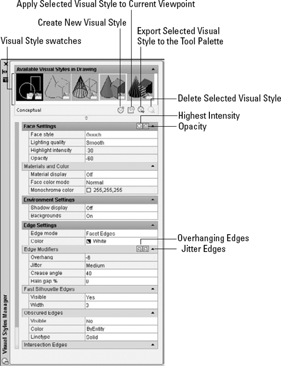
Two edge modifiers, overhang and jitter, help to provide a hand-drawn look. Jitter adds additional lines, as if you're sketching. Overhang extends lines past their ends, as shown in Figure 22.24.
You can also set overhang and jitter in the Visual Styles Manager, when you define a visual style. Click the Overhanging Edges and Jitter Edges buttons in the Edge Modifiers section and change the values of these items.
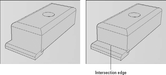
Intersection edges display lines where solids intersect. Figure 22.25 shows a model with a smaller box intersecting with a larger box. The left side does not display an intersection edge between the two boxes; the right side does.
When you're done designing your visual style, you can use the Apply Selected Visual Style to Current Viewport button to apply the visual style. The visual style also appears in the drop-down lists on the Home tab's View panel and the Render tab's Visual Styles panel, so you can choose it from either location. You can also use the Delete the Selected Visual Style button to delete your visual styles; however, you can't delete the styles that come with AutoCAD.
The SHADEMODE command in AutoCAD LT has only two options, 2D Wireframe and Hidden. The 2D Wireframe option allows you to turn off the shading that was set for one of the options available only in AutoCAD; you can use this when you open a drawing that was created in AutoCAD. However, AutoCAD LT has a SHADE command that provides the following options:
256 Color (0). Displays shaded faces. Shading is flat, but curved faces give the impression of gradual shading because they're broken up into many faces, each a slightly different color.
256 Color Edge Highlight (1). Similar to 256 Color, but highlights edges using the same color as your drawing background.
16 Color Hidden Line (2). Looks like a hidden display. The non-hidden edges are in the object's color, and the faces are the color of the background of the drawing area.
16 Color Filled (3). The reverse of 16 Color Hidden Line so that the faces are in the object's color, and non-hidden edges are the background color.
You control which shading method the SHADE command uses by changing the value of the SHADEDGE system variable. Type shadedge
In AutoCAD LT, you cannot edit your objects in Shaded mode, which is a better-looking version of the HIDE command. If you regenerate the drawing, the shading goes away.
Materials, textures, and lights are used in rendering, which is covered in Chapter 25. You can display materials and textures that you've attached to objects, even as you work, although doing so may slow down performance. You can also display lights. To display these features, you need to use the Realistic visual style, or a visual style that uses the Real face style.
Note
This section applies to AutoCAD only. AutoCAD LT does not include materials, textures, or lights, which is part of the rendering capability of AutoCAD.
Note
If you don't see lights or materials, they may be off due to Adaptive Degradation. AutoCAD automatically turns off certain features, based on the capability of your graphics card and overall computer system. For more information, see Appendix A.
Note
The drawing used in the following exercise on using and creating visual styles in a drawing, ab22-d.dwg, is in the Drawings folder on the DVD. This exercise is for AutoCAD only. AutoCAD LT doesn't offer these shading options.
STEPS: Using and Creating Visual Styles
Open
ab22-d.dwgfrom the DVD.Save it as
ab22-03.dwgin yourAutoCAD Biblefolder. This drawing should display the 3D Wireframe visual style.Choose Home tab
This time, choose 3D Hidden. Back lines disappear and the background is the same as for 3D Wireframe.
Choose the Conceptual visual style. The colors of the model change to blue and green.
Choose the Realistic visual style. This time, if your computer system can support it, you see the bronze satin material that I attached to the drawing.

Click the Create New Visual Style button near the top of the Visual Styles Manager palette. In the Create New Visual Style dialog box, enter MyRealistic in the Name text box. In the Description text box, enter No edges;silhouette. You want to create a visual style that doesn't show edges within the model but displays a thick silhouette around its outside. Click OK.
Change the following settings:
Material display: Material and textures
Edge Mode: None
Fast Silhouette Edges-Visible: Yes
Fast Silhouette Edges-Width: 9
Click the Apply Selected Visual Style to Current Viewport button. You see the change in the model. The internal edges disappear, but there's a thicker edge around the outside.
Close or hide the Visual Styles Manager. Choose Render tab
Laying out a 3D drawing on a layout tab is an important aspect of viewing a 3D drawing, because the layout determines the final output of the drawing. AutoCAD offers three commands that help you lay out your 3D drawing in paper space layouts: SOLVIEW, SOLDRAW, and SOLPROF. (Chapter 17 explains layouts.) Another command flattens 3D drawings to convert them to 2D profiles.
Note
These commands are available only in AutoCAD.
SOLVIEW automates the process of creating floating viewports and orthogonal views (views at right angles from each other).
UCS enables you to choose the UCS to work from, as well as set the scale, center, and clipping corners of a floating viewport. Use this option first. After you choose a UCS, type in a scale. You can change this later if you want. SOLVIEW then prompts you for the center of the view. Pick a point and wait until the 3D model regenerates. SOLVIEW continues to prompt you for a view center, letting you pick points until you like what you see. Press Enter to continue the prompts. The clipping corners are the corners of the viewport. At the
Enter view name:prompt, type a name. SOLVIEW creates the first viewport.Choose a view name that describes the view, such as Top, Side, or East Elevation. This helps you when you start creating orthogonal views.
Ortho creates orthogonal views. At the
Specify side of viewport to project:prompt, pick one of the edges of the first viewport. Again, choose a view center and clip the corners to create the viewport. Type a name for this new view.If you don't see the model properly when you pick the view center, continue with the prompts, picking clipping corners where you want them. (This problem can happen when you have several separate 3D objects in your drawing.) Then pick the viewport (in model space with tile off) and do a Zoom Extents. You can then pan and zoom as you want.
Auxiliary creates inclined views. At the
Specify first point of inclined plane:prompt, pick a point in one of the viewports. At theSpecify second point of inclined plane:prompt, pick another point in the same viewport. The two points are usually at an angle to create the inclined view. At theSpecify side to view from:prompt, pick a point. You then pick a view center and clipping corners, and then specify a view name.Section creates cross-sections. At the
Specify first point of cutting plane:prompt, pick a point in a viewport. At theSpecify second point of cutting plane:prompt, pick a point on the opposite side of the model to create a cross-section. You then pick a side to view from, and enter the view scale, a view center, clipping corners, and a view name.
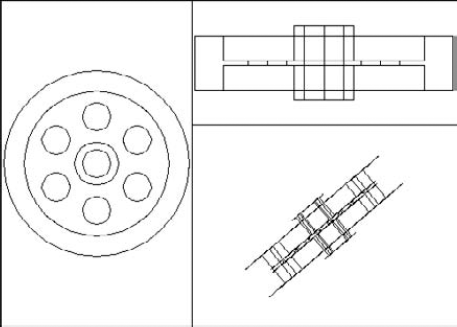
Figure 22.27 shows an example with a top view, an auxiliary view, and a section.
Using SOLDRAW to create hidden lines and hatching
To use SOLDRAW, choose Home tab
SOLDRAW uses hatch pattern defaults to define the hatch. You may have to change these settings by using HATCHEDIT.
Note
SOLVIEW creates a whole set of new layers in your drawing. SOLDRAW freezes your original layers, leaving visible only the layers that are needed to display the profile in that paper space viewport. SOLVIEW creates a special layer that you can use for dimensioning — one for each view that you create. For a view named front, the layer is named front-dim. You can use these dimensioning layers to create dimensions in paper space.
Note
When you start SOLPROF, you must have already created a floating viewport, and you must be in model space. Double-click inside any viewport to enter model space.
At the Display hidden profile lines on separate layer? [Yes/No] <Y>: prompt, type Y or N
At the Project profile lines onto a plane? [Yes/No] <Y>: prompt, type Y or N
At the Delete tangential edges? [Yes/No] <Y>: prompt, type Y or N
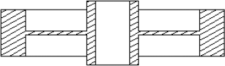
Figure 22.29 on the left shows the result of SOLPROF after freezing the layer that contains the original object; SOLPROF creates its own layers for the profile. Figure 22.29 on the right shows the result of SOLPROF after also freezing the layer that SOLPROF created, which contains the hidden parts of the model. In this case, the layer was named PH-159. Look for the H in the layer name, which stands for hidden. The last part of the layer name is the handle of the object that you're profiling, so it differs for each object.
You can combine viewports created with SOLPROF and viewports created with SOLVIEW and SOLDRAW. For example, you can create two orthogonal views with SOLVIEW and SOLDRAW, and then add a viewport and use SOLPROF to create another view.
Tip
As soon as you have a separate layer for the hidden portion of the model, you can modify that layer's color and/or linetype to show the hidden lines in a contrasting color or linetype.
You may want to create a 2D representation of a 3D drawing. Some reasons to do this are for technical illustrations and to keep the core models of a drawing confidential. The FLATSHOT command takes all 3D objects in a drawing and makes 2D blocks from them. You can put objects that you don't want to include on off or frozen layers. This feature is available in AutoCAD only.
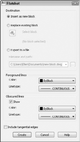
In the Destination section, you decide where the 2D objects will go. You can insert them in the current drawing as a new block, replace an existing block, or export them to a new drawing. In the Foreground Lines section, you choose the color of the lines of the objects. Foreground lines are those that would not be hidden in 3D Hidden visual style. In the Obscured Lines section, you decide how to treat lines that would be hidden in 3D Hidden visual style. You can choose not to display them, for a hidden look, or use a different color or linetype. Click OK when you're done.
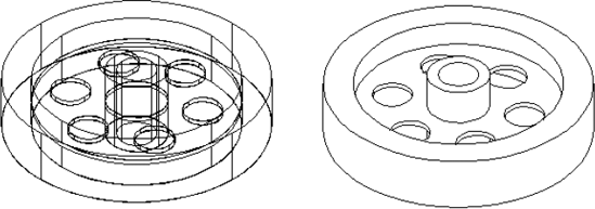
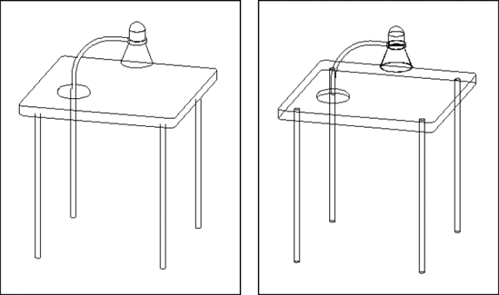
If you chose to insert a new block, place the block. If you chose to export to a new file, open that file. You will probably have to Zoom to Extents to see the block. Figure 22.31 shows the results, both with and without obscured lines.
Note
The FLATTEN command is an Express Tools command that also creates 2D representations of 3D objects. In addition, it reduces elevation and thickness to 0. It is available only on the command line.
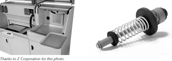
Stereolithography, or 3D printing, is a way of quickly creating prototypes. A 3D printer uses information from a drawing to deposit layer upon layer of a plastic, metal, or composite material, until the model is completed. Models can even be functional objects. In this way, 3D printing can allow you to see and test your 3D model. These models can also be used to show the customer what the final object will look like. Figure 22.32 shows a 3D printer and a sample model.
A 3D printer works from an STL file, which translates the drawing information into a format that the printer can understand. The STL file converts the drawing model to a faceted mesh representation consisting of a set of triangles. You can use the FACETRES system variable to control facet density.
Note
In order to export a model to an STL file, it must be completely in the positive range of the X, Y, and Z axes.
To export a model to an STL file, choose Application Button
In this chapter, I covered all the ways to view your 3D drawing. You read about:
Using the standard viewpoints for a quick look.
Utilizing the DDVPOINT command to specify exact angles.
Working with the ViewCube to change viewpoints.
Creating a named 3D view with a camera.
Adding a background to a named view.
Using the tripod and compass for flexibility.
Using the PLAN command to quickly return you to plan view.
Displaying parallel and perspective projections.
Applying 3D Orbit to view your model from any position. You can zoom and pan, create parallel and perspective views, and set clipping planes. You can also create a continuously moving orbit.
Using ShowMotion to cycle through views.
Walking and flying through a drawing. You can navigate through a drawing and save a movie file of the result. You can also save an animation of a motion path.
Using the DVIEW command to let you create parallel and perspective views. You set the camera and target where you can create front and back clipping planes.
Using the SteeringWheel, a feature that combines several navigational and view-related tools.
Using and creating visual styles to determine how your drawing looks. Also, using the shading options in AutoCAD LT.
Employing the three commands — SOLVIEW, SOLDRAW, and SOLPROF — that help you lay out views of a 3D drawing for plotting.
Using the FLATSHOT command, which creates 2D blocks from 3D objects.
Exporting to STL format for 3D printing.
In the next chapter, I explain how to create 3D surfaces.