
Dimensions are an important part of most drawings. Dimensions indicate the measurement of the models that you've created and are used in the manufacturing process. The dimensions in AutoCAD and AutoCAD LT offer a great deal of flexibility. In this chapter, I cover the process of drawing dimensions. In the next chapter, I explain how to customize the format of your dimensions by using dimension styles. (Even though you should create a dimension style before you dimension, you need to understand dimensions before you can create a style; therefore, I cover dimensions first.)
You usually add dimensions after you complete all or most of a drawing. When you dimension a drawing all at once, you can create a unified, organized look for your dimensions. Before you can dimension a drawing, you need to understand the elements of a dimension and how to prepare for dimensioning.
Note
In Chapter 17, I explain how to dimension a drawing on a paper space layout and also how to work with annotative dimensions that automatically scale according to the scale of the drawing. In Chapter 15, I explain how to create a dimension style, including one that is annotative.
A dimension is a complex object, containing many parts. Figure 14.1 shows a typical linear dimension.
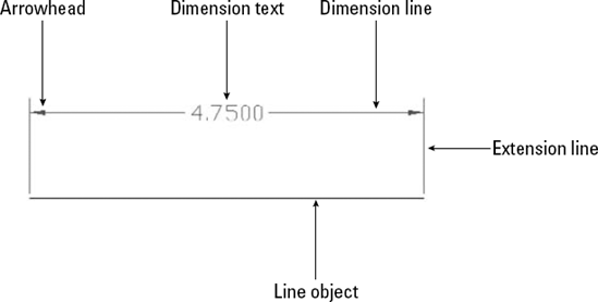
The parts of a dimension are:
Extension lines. These extend from the dimensioned object to the dimension line and arrowheads. A small gap usually separates the dimensioned object and the start of the extension lines. Extension lines visually clarify the extents of the object being dimensioned.
Note
Relative to dimensions, the word extension (or extend) is used in two other ways besides referring to extension lines. First, the extension line itself usually extends from the object being dimensioned past the dimension line. You can specify the amount of this extension. Second, in architectural dimensions, the dimension line extends past the extension lines. You can specify this extension as well.
Dimension text. This tells you the actual measurement of the dimensioned object. You can format this text in decimals, fractions, scientific units, and so on.
Dimension line. This extends between the extension lines.
Arrowheads. These mark the intersection of the dimension line and the extension lines. They can take several forms, such as tick marks, open arrows, or dots.
Dimensions have two important characteristics:
Dimensions are blocks. I have mentioned blocks earlier in this book, and they are fully covered in Chapter 18. Blocks are groups of objects that you can manipulate as one object. As a result, if you pick a dimension, all parts of the dimension are selected.
Dimensions are associative. This means that an association connects the dimension and the object it dimensions. If you change the size of the object, the dimension automatically adjusts appropriately.
All parts of a dimension can be formatted individually. You generally format a dimension by creating a dimension style, which is a named set of formats for dimensions — just as a text style is a named set of formats for text. (Dimension styles are the topic of the next chapter.)
Dimensioning requires some preparation to get the result that you want. Before starting to create dimensions, you should prepare as follows:
Create a layer for your dimensions. It's important that dimensions be easily distinguishable from the rest of your drawing. The color is usually a contrast to that of your models. For example, if your models are black (and you're working on a white screen), you might want your dimensions to be green, magenta, or cyan.
Tip
If you often turn layers on and off (or freeze and thaw them), you may want to create a separate dimension layer for each layer of drawing data. For example, if you dimension an electrical layer that you turn off regularly, you can have a special Dim-elec dimension layer that you can turn off with the electrical layer.
Note
If you're dimensioning an existing drawing that was created in a pre-2002 version of AutoCAD or AutoCAD LT, turn on associative dimensioning with the DIMASSOC system variable. Type dimassoc

Create a text style for your dimensions. If you want your dimensions to be annotative, make sure that the text style is annotative. For more information, see Chapter 13.
Tip
Set the height of the text style to zero. You can then set the text height when you create the dimension style. If you do specify a fixed height in your text style, that height overrides any height that you specify in the dimension style.
Right-click the Object Snap button on the status bar and choose Setting. Then set all the running object snaps that you want. Endpoint and Intersection are a necessity. Add Center and Quadrant if you need to dimension arcs and circles. Click the Object Snap button on the status bar to turn it on.
Create a dimension style. If you want your dimensions to be annotative, make sure that the dimension style is annotative. The next chapter covers dimension styles. Annotative dimensions are valuable when you will be displaying your model at more than one scale, in separate viewports.
Save your dimension layer, dimension text style, and dimension style in your drawing templates.
If you want your dimensions to be annotative, change to the desired annotation scale, using the Annotation Scale list on the status bar. (You can add or delete annotation scales later if you need to.)
The Annotation panel on the Home tab offers most of the dimensioning commands. You can find the complete set on the Annotate tab in the Dimensions panel.
Just as the most common objects are lines, the most common dimensions are linear dimensions. Use linear dimensions for lines, or a straight segment of a polyline. You can also use a linear dimension for arcs and circles — you get the linear length of the arc (not its perimeter length) and the diameter of the circle.
If you're dimensioning more than one object, such as the distance from the endpoint of one line to the endpoint of another line, pick the first extension line origin. At the
Specify second extension line origin:prompt, pick the second extension line origin. The two points on the objects that you pick define the length of the dimension.If you're dimensioning one object, press Enter at the
Specify first extension line origin or <select object>:prompt. TheSelect object to dimension:prompt appears. Pick the object.
Warning
Always use the Select Object option if possible, for the most reliable results. Proper association of dimensions with their objects depends on the points that you specify. If you can't select an object and the point you need to specify is an intersection, don't click on the intersection. Instead, click on the object that you want to measure near the intersection and let the object snap specify the intersection for you. If you're not using the Select Object option, always use an object snap for accuracy.
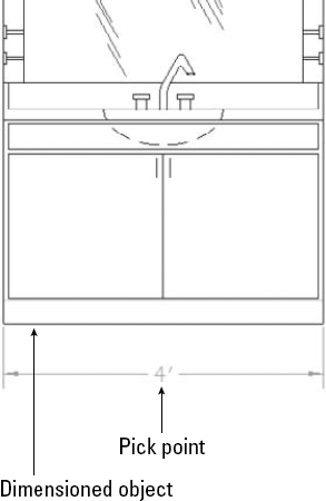
At the Specify dimension line location or [Mtext/Text/Angle/Horizontal/Vertical/Rotated]: prompt, pick a point for the location of the dimension line. As you move the mouse, you can see the results on your screen, as shown in Figure 14.2. If you want an exact location, you can type in a relative coordinate, such as @0,.5 to specify that the dimension line should be 0.5 units from the object. Snap mode may also work well for you, depending on the drawing environment.
Object snap tracking makes it a snap to pick points for dimensioning. For example, if you're dimensioning a house, your first extension line origin may be the outside corner of the house, but the second extension line origin may be an inner wall. At the Specify first extension line origin or <select object>: prompt, move the cursor over the inner wall endpoint to acquire it. Move the cursor back to the line you're dimensioning and click when you see the tooltip showing the snap point you chose. The dimension goes just where you need it.
Note
The drawing used in the following exercise on drawing linear dimensions, ab14-a.dwg, is in the Drawings folder on the DVD.
STEPS: Drawing Linear Dimensions
Open
ab14-a.dwgfrom your DVD.Save the file as
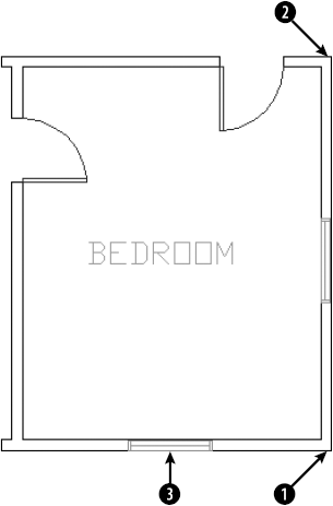
ab14-01.dwgin yourAutoCAD Biblefolder. This is a plan of a bedroom, as shown in Figure 14.3. Ortho mode and Object Snap should be on. Set a running object snap for Endpoint only. Object Snap Tracking should be off. The current layer should be set toDim.
Repeat the DIMLINEAR command. At the
Specify first extension line origin or <select object>:prompt, press Enter. At theSelect object to dimension:prompt, pick
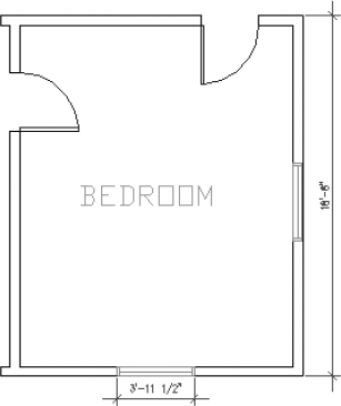
Save your drawing. It should look like Figure 14.4.
You can also use one of the options offered at the command prompt to further control the final dimension. Dimension options control the text and the angle of the dimension.
The Mtext option lets you replace the calculated dimension text or add a prefix or suffix to it. When you right-click and choose Mtext at the Specify dimension line location or [Mtext/Text/Angle/Horizontal/Vertical/Rotated]: prompt, the In-Place Text Editor opens. The Text Editor tab appears on the ribbon and the dimension text is highlighted in your drawing. (If you are using the AutoCAD Classic or AutoCAD LT Classic workspace, you'll see the In-Place Text Editor toolbar.)
The best use of the Mtext option is to add some text before or after the measurement, such as TYP (typical used when one dimension applies to several objects) or subject to final approval. To add text before the measurement, simply start typing. To add text after the measurement, press the End or right arrow key and then type. To replace the existing text, click the text to select it and enter the replacement text. Then click outside of the In-Place Text Editor to close it.
Note
Typing your own dimension text is most commonly used where a dimension represents several sizes and refers to a size chart elsewhere in the drawing. For example, the text "Dim A" might be used for this purpose. If you replace the existing text, you can obtain the original text again by editing the dimension (double-click the dimension) and changing the Text Override item in the Properties palette to <>.
If the measurement text itself does not appear the way you want it, you should change the annotation specifications in the dimension style. You can also specify a prefix or suffix (such as mm) for all dimensions, as I explain in the next chapter. When you delete the text and type your own dimension text, you lose the ability of the dimension's measurement to automatically adjust to any change in the object's size.
Tip
To add text below the dimension line, enter X after the dimension text. Any text after the X goes below the dimension line. The "X" must be uppercase.
The Text option also lets you change dimension text but does not open the In-Place Text Editor. Instead, you can quickly retype the entire dimension text as you want it on the command line.
The angle of the text (horizontal, vertical, or aligned) is specified in your dimension style. However, you can use this option to change the angle of the dimension text for a particular circumstance. Right-click and choose Angle to get the Specify angle of dimension text: prompt. Type in an angle or pick two points to align the text with an existing object.
The DIMLINEAR command assumes that you want a horizontal dimension if you select a horizontal object or two definition points running horizontally — ditto for a vertical dimension. Also, if you want to draw a vertical dimension of an object at an angle, you can specify this simply by[bm1] moving the mouse cursor horizontally when specifying the dimension line location, as shown in Figure 14.5. If for some reason you need to force either a horizontal or vertical dimension, you can use the vertical or horizontal options.
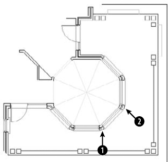
Use a rotated linear dimension when the length that you want to dimension is not parallel to the extension line origins. Just as the vertical dimension in Figure 14.5 does not measure the length of the line to which its extension lines extend, a rotated linear dimension does not measure a specific object, but the distance of an imaginary line parallel to the dimension line. Rotated dimensions are not very common, but when you need them, they're the only way to get the dimension measurement that you need.
To use a rotated dimension, start a linear dimension, pick the two extension line origins, and choose the Rotated option. At the Specify angle of dimension line <0>: prompt, type the angle (or pick two points) to draw the dimension.
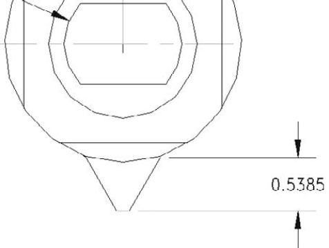
Figure 14.6 shows a hexagonal steppingstone with a rotated linear angle. The extension lines of the dimension extend to a line at 104.5 degrees, but in this case you want to measure a length at an angle of 135 degrees. Note that the dimension really measures an imaginary line parallel to the dimension line, shown in the figure as a dashed line, rather than the side of the hexagon.
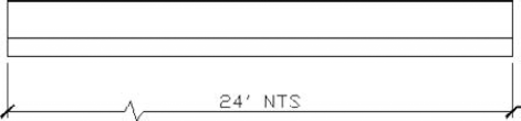
A jog line is a zigzag used to indicate that the displayed measurement doesn't match the length of an object. For example, you might shorten an object to display it within a certain area, but manually override the dimension text to show the proper length. In this case, the jog line indicates that the visual length of the line is not to scale (NTS).
You can move the jog line by stretching its grip. Select the dimension, select the jog line's grip, and move it to another location.
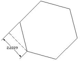
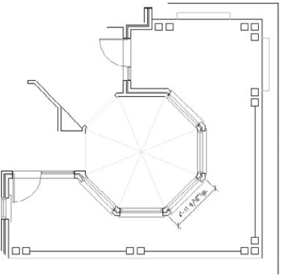
When you want to dimension a linear object that is not orthogonal, use an aligned dimension. The dimension lines of an aligned dimension are always parallel to the object, unlike rotated dimensions. An aligned dimension measures the actual length of the object, not a vertical or horizontal distance that you dimension with a linear dimension. Therefore, your choice of linear, linear rotated, or aligned dimension depends on the distance that you want to measure. Figure 14.8 shows several aligned dimensions.
You then see the Specify dimension line location or [Mtext/Text/Angle]: prompt. Pick a point for the location of the dimension line. If you want an exact location, you can type in a relative coordinate, such as @2<45.
After you've chosen what you want to dimension, you have three options: Mtext, Text, and Angle. The previous section discusses these options in detail.
Note
The drawing used in the following exercise on drawing aligned dimensions, ab14-b.dwg, is in the Drawings folder on the DVD.
STEPS: Drawing Aligned Dimensions
Open
ab14-b.dwgfrom your DVD.Save the file as
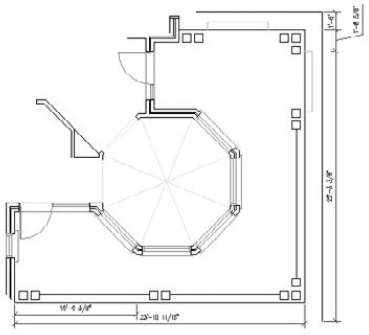
ab14-02.dwgin yourAutoCAD Biblefolder. This is part of a floor plan of a house, as shown in Figure 14.9. Object Snap should be on. Set running object snaps to Endpoint and Intersection.
Specify first extension line origin or <select object>:
Choose
in Figure 14.9. Specify second extension line origin:Choose
in Figure 14.9. Specify dimension line location or [Mtext/Text/Angle]:Right-click and choose Mtext. In the In-Place Text Editor, press the End key on the keyboard and type a space, then typeTypClick outside of the In-Place Text Editor. Specify dimension line location or [Mtext/Text/Angle]:Pick a location for the dimension line.Save your drawing. It should look like Figure 14.10.
Often, you want to create a whole series of attached, connected dimensions. You can accomplish this in two ways:
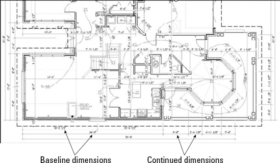
Baseline dimensions are a series of dimensions that all start from one point. The first extension line is the same for all the dimensions. The second dimension includes the first dimension plus an additional distance, and so on.
Continued dimensions are a series of dimensions that are all attached. The second dimension starts where the first dimension ends, and so on. Each dimension measures a different object or distance.
Figure 14.11 shows both baseline and continued linear dimensions. You can also create baseline and continued angular and ordinate dimensions. Quick Dimension, covered later in this chapter, can quickly create baseline and continued linear dimensions. Here I cover the traditional method.
If the previous dimension was a linear, angular, or ordinate dimension, the command uses the first extension line as the base for the new baseline dimension. Specify a new second extension line origin, and the command creates the baseline dimension with the same first extension origin as the original dimension and the new second extension origin that you just specified.
If you don't want to work with the previous dimension in the drawing, press Enter. The command responds with the Select base dimension: prompt. Be careful to pick the dimension closer to the side you want to use as the baseline. The command then prompts you to specify a second extension line origin.
The command continues to prompt you for second extension line origins so that you can quickly create a chain of baseline dimensions. At each prompt, you can right-click and choose Undo to undo the previous dimension. You can also press Enter at any time and select a different dimension from which to work. Press Esc to end the command (or press Enter twice).
If the previous dimension was a linear, angular, or ordinate dimension, the command uses the second extension line as the beginning of the new continued dimension. Specify a new second extension line origin to create the continued dimension.
If you don't want to continue from the previous dimension in the drawing, press Enter. The command responds with the Select continued dimension: prompt. Be careful to pick the dimension closer to the side from which you want to continue. You then get a prompt to specify a second extension line origin.
The command continues to prompt you for second extension line origins so that you can quickly create a chain of continued dimensions. At each prompt, you can right-click and choose Undo to undo the previous dimension. You can also press Enter at any time and select a different dimension from which to work. Press Esc to end the command (or press Enter twice).
Note
The drawing used in the following exercise on drawing baseline and continued dimensions, ab14-b.dwg, is in the Drawings folder on the DVD.
STEPS: Drawing Baseline and Continued Dimensions
Open
ab14-b.dwgfrom your DVD.Save the file as
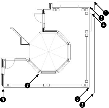
ab14-03.dwgin yourAutoCAD Biblefolder. This is the same drawing used in the previous two exercises, as shown in Figure 14.12. Object Snap should be on with running object snaps for Endpoint and Intersection.Turn on Ortho mode and Object Snap Tracking on the status bar.
Choose Annotate tab

Specify first extension line origin or <select object>:
Pick the endpoint atin Figure 14.12. Specify second extension line origin:Pass the cursor overto acquire it for object snap tracking. Move the cursor to the right so that it's vertically under, and click when you see the 1'-6″<0° tooltip. Specify dimension line location or [Mtext/Text/Angle/Horizontal/Vertical/Rotated]:Pick a dimension line location to the right of the model.
At the
Specify a second extension line origin or [Undo/Select] <Select>:prompt, move the cursor over the endpoint or intersection at
This action places the continued dimension. Notice that the dimension uses a leader to place the text because there is not enough room between the extension lines. (If the leader is placed to the left, select it and pick the grip on the text. Pick a point to the right of the model and click to move the leader to the right.)
The command repeats the
Specify a second extension line origin or [Undo/Select] <Select>:prompt. Pick the endpoint atRepeat the DIMLINEAR command. Follow the prompts:
Specify first extension line origin or <select object>:
Choose the endpoint at
in Figure 14.12.Follow these prompts:
Specify second extension line origin:
Move the cursor over
to acquire it. Move the cursor down so that it's horizontal to. When you see the 4′0″<270° tooltip, click. Specify dimension line location or [Mtext/Text/Angle/Horizontal/Vertical/Rotated]:Pick a dimension line location fairly close to the line you dimensioned, leaving just enough room for the dimension text.
Save your drawing. It should look like Figure 14.13.
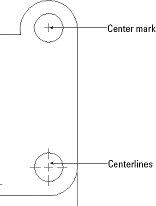
When you dimension an arc or a circle, you measure its radius or diameter. It's also common to mark arc and circle centers to clarify what you're measuring. Arc and circle dimensions are most commonly used in mechanical drawings.
Circle and arc centers are often marked in mechanical drawings because the center is an important aspect of a circle or arc but is not obvious without a mark. You set the size and type of mark when you create a dimension style, as explained in the next chapter. You can use a center mark (a small cross) or centerlines, as shown in Figure 14.14.
You can also choose the Mtext, Text, or Angle option, as described in the section "Drawing Linear Dimensions." The Partial option lets you dimension part of an arc. At the prompts, you specify where you want to start and end the dimension. The Leader option inserts an arrow pointing to the arc.
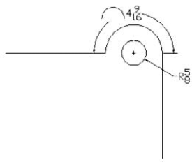
Figure 14.15. The circle's radius dimension uses a leader (a line and arrow pointing to the object) because the circle is too small to place the dimension inside it. The arc displays an arc length dimension.
You can also choose the Mtext, Text, or Angle option, as described in the "Drawing Linear Dimensions" section earlier in this chapter.
A radius dimension usually passes through the center of the arc or circle. If you are dimensioning a large arc or circle, you may find that you can't see the center at the same time as you see the circumference without zooming out too far. In this instance, you can use the jogged radial dimension, which lets you specify an arbitrary center for the arc or circle. Choose Home tab
You can create an extension arc (similar to an extension line) for a radius dimension that extends beyond the end of an arc. This allows you to place the dimension anywhere in the circle of which the arc is a part. When you specify the location of the dimension, just move the cursor past the arc's endpoint and continue around to the desired point.
You can also choose the Mtext, Text, or Angle option, as described in the section "Drawing Linear Dimensions."
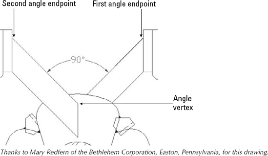
You have several options for dimensioning angles. You may want to dimension the angular relationship between two lines, but the lines may intersect at their midpoints or may not intersect at all. Therefore, you need to be able to specify the vertex of the angle you want to dimension. Figure 14.16 shows an angular dimension with the points used to define it.
If you press Enter, the command asks for the angle vertex, the first angle endpoint, and the second angle endpoint. These three points define the angle.
If you select an arc, the command dimensions the entire arc, using the arc's center as the angle vertex.
If you select a circle, the command uses the pick point as the first angle endpoint and the circle's center as the angle vertex. You then see the
Specify second angle endpoint:prompt. Pick a point on the circle.If you select a line, the command asks for a second line. The command measures the angle between the two lines. If the lines don't intersect, the command uses their implied intersection as the angle vertex.
After you define the angle, the command responds with the Specify dimension arc line location or [Mtext/Text/Angle/Quadrant]: prompt. Pick a point for the dimension arc line — which is the same thing as a dimension line, except that the command uses an arc for angular dimensions.
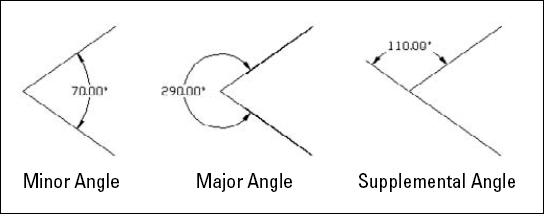
Dimensioning minor, major, and supplemental angles
When two lines meet at an angle, they create two angles, the minor angle and the major angle. The angle that is less than 180 degrees is the minor angle. The major angle is always more than 180 degrees. You can also measure the supplemental angle, which is the difference between 180 degrees and the minor angle. These angles are shown here.
Here's how you create each type of dimension. Start the DIMANGULAR command. The command responds with the Select arc, circle, line, or <specify vertex>: prompt.
To dimension the minor angle, select both lines. Then at the Specify dimension arc line location or [Mtext/Text/Angle/Quadrant]: prompt, place the dimension arc line inside the angle, as shown in the figure. (You can also press Enter, specify the angle vertex and the two lines, and place the dimension arc line inside the angle.)
To dimension the major angle, press Enter. Do not select the lines. At the prompts, specify the angle vertex and the two lines. At the Specify dimension arc line location or [Mtext/Text/Angle/Quadrant]: prompt, place the dimension arc line outside the angle, as shown in the figure.
To dimension the supplemental angle, select both lines. At the Specify dimension arc line location or [Mtext/Text/Angle/Quadrant]: prompt, place the dimension arc line outside the angle, as shown in the figure.
As you can see, how you specify the angle and where you place the dimension arc line determine which angle you measure.
The Quadrant option lets you lock the location of the dimension line to a specified quadrant of the circle in which the angle lies. For example, you can fix the dimension line outside two lines forming an angle while placing the text within those two lines. After choosing the Quadrant option, at the Specify quadrant: prompt, click where you want the dimension line to appear. You can then specify any location for the text of the dimension line. You can also choose the Mtext, Text, or Angle option, as covered in the section "Drawing Linear Dimensions."
In the following exercise, you practice drawing radial, diameter, and angular dimensions.
Note
The drawing used in the following exercise on drawing radial, diameter, and angular dimensions, ab14-c.dwg, is in the Drawings folder on the DVD.
STEPS: Drawing Radial, Diameter, and Angular Dimensions
Open
ab14-c.dwgfrom your DVD.Save the file as
ab14-04.dwgin yourAutoCAD Biblefolder. This is a view of a bearing housing for an industrial washing machine, as shown in Figure 14.17. Object Snap mode should be on. Set running object snaps to Endpoint, Intersection, and Center.


Select arc, circle, line, or <specify vertex>:
Specify angle vertex:Pickin Figure 14.17. Specify first angle endpoint:Pick the endpoint at. (Press Tab if necessary until you see the endpoint tooltip.)Specify second angle endpoint:Pick the endpoint at. Specify dimension arc line location or [Mtext/Text/Angle/Quadrant]:Choose a location for the dimension line.Repeat the DIMANGULAR command. At the
Select arc, circle, line, or <specify vertex>:prompt, pick the arc at

Start the DIMANGULAR command. At the
Select arc, circle, line, or <specify vertex>:prompt, pickSave your drawing. It should look like Figure 14.18.
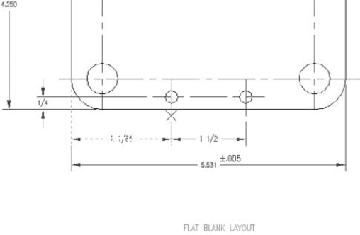
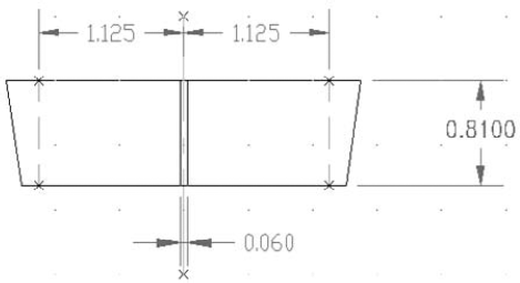
Ordinate dimensions are used in mechanical drawing. They dimension an object by labeling X or Y coordinates based on a 0,0 coordinate placed somewhere on the model. Figure 14.19 shows a drawing with some ordinate dimensions.
To place the 0,0 coordinate on the model, choose View tab
At the Specify leader endpoint or [Xdatum/Ydatum/Mtext/Text/Angle]: prompt, pick the endpoint for the leader. The location where you pick the leader endpoint determines which coordinate to dimension — the X coordinate (Xdatum) or Y coordinate (Ydatum). Pick the leader endpoint perpendicular from the coordinate's axis that you want to measure. To measure an X coordinate, move up or down from the feature you selected. To measure a Y coordinate, move left or right to pick the leader endpoint.
Usually you work with Ortho mode on to create straight lines. If you need to create bent lines to avoid previously drawn dimensions, turn Ortho mode off. If you pick a leader endpoint at a nonorthogonal angle from the feature, you may need to force the measurement of the coordinate that you want by using either the Xdatum or Ydatum option. Use the Mtext option to open the In-Place Text Editor and edit the dimension text. Use the Text option to change all the text on the command line.
To perfectly line up the dimensions, when specifying the leader endpoint, use object tracking to track the endpoint of the previous leader. You can also turn on SNAP.
Note
The drawing used in the following exercise on drawing ordinate dimensions, ab14-d.dwg, is in the Drawings folder on the DVD.
STEPS: Drawing Ordinate Dimensions
Open
ab14-d.dwgfrom your DVD.Save the file as
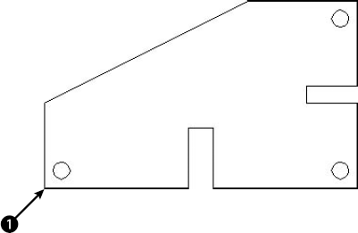
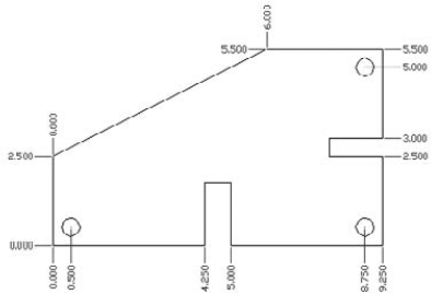
ab14-05.dwgin yourAutoCAD Biblefolder. This drawing shows a simple sheet-metal template, as shown in Figure 14.20. Snap should be on and a snap distance of 0.25 units set. Right-click the Snap Mode button on the status bar and make sure that Grid Snap is on.Choose View tab

Repeat the DIMORDINATE command. At the
Specify feature location:prompt, chooseContinue to dimension the drawing, using Figure 14.21 as a guide.
Tip
Type multiple
Save your drawing.
Leaders are lines pointing to objects. At the end of a leader, you place any text that you want. Use leaders to label objects or provide explanatory text. Leaders do not calculate dimension text, but if you use an object snap to place the arrow point, they follow along if you move the object. Figure 14.22 shows two leaders.
Multileaders are leaders that support multiple lines. You format a multileader by configuring multileader styles. Multileader styles can be annotative, which allows them to scale automatically to the current annotative/viewport scale.
Note
Earlier QLEADER and LEADER commands still exist, but they offer fewer options.
The In-Place Text Editor opens, where you can enter the text for the leader. (See Chapter 13 for a discussion of the text editor.) You can use the editor to format the text at this time. For example, you can choose an existing text style, a font, or a font size. Close the editor to place the leader. Notice that the command adds a short horizontal landing line that connects a diagonal arrow to the text.
When you start the MLEADER command, you have the following options at the first prompt:
leader Landing first. Lets you first specify the point where the line meets the text. If you choose this option, AutoCAD continues to prompt you for the leader landing first.
Content first. Lets you specify a location for the text label, and then enter the text.
Options. Displays the following suboptions:
Leader type. Offers you options relating to the leader. You can use the Type suboption to choose a straight line (the default), a spline, or no line at all. Choose the Landing suboption to choose whether or not you want a landing, and if so, its length.
leader lAnding. Lets you choose whether you want a landing (Yes) or not (No).
Content type. Lets you choose whether you want the leader to end with Mtext (the default), a block, or nothing. If you choose the Block suboption, you enter the name of the block. (Blocks are covered in Chapter 18.)
Maxpoints. Lets you specify the maximum number of points of the line. A three-point line will have three vertices.
First angle. Lets you enter an angle to constrain the first angle after the arrowhead segment. For example, you could constrain the angle to 90°.
Second angle. If you specified more than two points, you can constrain a second angle.
eXit options. Exits the Options prompts and returns you to the main prompts for the MLEADER command.
Note
You can press the Ctrl key and pick a segment of a multileader, to select just that segment. You can then change the properties of that segment in the Properties palette (Ctrl+1).
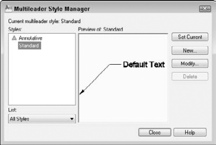
Although you have a lot of settings available when you create a multileader, you can best define its look by using a multileader style. Because you save a style, you can easily use it again and again.
To create a new style, click the New button to open the Create New Multileader Style dialog box. Here you name your style and choose an existing style as a basis for the style. You can also specify that the style should be annotative by checking the Annotative check box. Note that if you want the multileaders to be annotative, then any blocks and text styles that they use need to be annotative, as well.
Note
Annotative objects scale automatically to the current annotative/viewport scale when you plot them. For more information, see Chapter 17. For information about annotative text styles, see Chapter 13. I cover blocks in Chapter 18.
When you've named your style, click Continue to open the Modify Multileader Style dialog box, shown in Figure 14.24 with the Leader Format tab displayed. If you choose an existing multileader style from the Multileader Style Manager and click Modify, you get to this same dialog box.
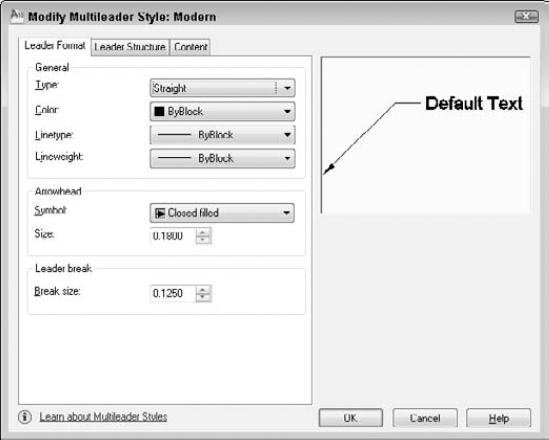
On the Leader Format tab, you can format the line and the arrow as follows:
Type. Choose Straight, Spline (curved), or None from the drop-down list.
Color. Choose a color from the drop-down list. These are the same colors that you can choose for any object. For more information, see Chapter 11. The default is ByBlock, which means that the leader takes on the color of the current layer (or the current color).
Linetype. Choose a linetype from the drop-down list. Choose Other to open the Select Linetype dialog box, where you can choose a loaded linetype, or load another linetype. (I explain linetypes in Chapter 11.)
Lineweight. Choose a lineweight from the drop-down list. (Chapter 11 discusses lineweights.)
Symbol. In the Arrowhead section, you can choose the type of arrow you want to use from the drop-down list.
Size. Enter an arrowhead size, or use the up and down arrows to change the current size.
Break size. Enter a value for a break to use with the DIMBREAK command. (I explain the DIMBREAK command later in this chapter.)
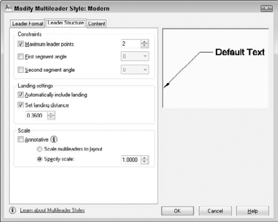
On the Leader Structure tab, shown in Figure 14.25, you specify some more detailed information about the leader's line:
Maximum Leader Points. By default, a leader line has two points. You can allow for more vertices by adding points.
First Segment Angle. You can constrain the angle of the first segment, which is horizontal by default. Choose from 15° increments up to 90°.
Second Segment Angle. You can constrain the angle of the second segment, which is horizontal by default. Choose from 15° increments up to 90°.
Automatically Include Landing. In the Landing Settings section, you can decide whether you want a horizontal landing (the short line next to the text). Uncheck the check box if you don't want one.
Set Landing Distance. To specify the length of the landing line, check this check box and enter a value in units.
Annotative. In the Scale section, check this check box to make the multileaders annotative, as explained earlier in this section. If the multileaders are not annotative, you can automatically scale them to the scale of the viewport or specify a scale for all multileaders.
The Content tab offers settings related to text and the label part of the leader. First, you specify the Multileader Type, which can be Mtext, a block, or nothing at the end of a leader.
Mtext. If you choose Mtext (multiline text), you specify default text content (if any), the text style, text angle, and text color. You specify the text height (which is the paper height if the style is annotative). You can force the text to be left-justified in all situations. Check the Frame Text check box to put a box around the text. Finally, you specify how the landing line attaches to the text and the gap between the landing line and the text.
Note
You can click the Ellipsis button next to the Text Style item to open the Text Style dialog box, where you can create a new text style or modify an existing one. You can now specify a vertical attachment (from the top or bottom of the leader text) as well as a horizontal attachment (from the side of the leader text).
Block. If you choose a block, you either specify one of several standard blocks or your own block (User Block). The standard blocks are detail callout, slot, circle, box, hexagon, and triangle. The blocks contain attributes (discussed in Chapter 18) that allow you to add a number (or a letter) inside each shape. For example, you might label various parts of the drawing A, B, and C. Usually, you would then have some annotation elsewhere to provide further information about these objects. You also choose how the landing line attaches to the block and the block's color.
Note
You can now scale the block. Enter a scale in the Scale text box. You see the result immediately in the preview pane.
Throughout this process, the preview window displays a representation of how the multileader will look. Note, however, that several features depend on how you insert the leader. For example, you don't see any difference in the preview when you constrain the leader line's angles. When you're done, click OK and then Close to return to your drawing.
Your multileader style is now current, and you can use it to draw multileaders. To change a current style, choose it from the Multileader Style drop-down list in the Leaders panel of the Annotate tab. You can also find it by choosing Home tab
Two commands allow you to align multileaders and combine them. You align leaders to make them look more orderly, using the MLEADERALIGN command. There are several options that you can use, depending on the desired result.
At the Select multileader to align to or [Options]: prompt, you specify the multileader that you want to act as a basis for the others. The command then aligns the other multileaders with this one. At the Specify direction: prompt, you can specify a direction for the alignment. This default use of the command does not align the multileader lines or the arrows, just the end of the landing line nearest the Mtext or block. In most cases, you'll probably want to use a vertical alignment; in this case, the ends of the landing lines align, all in a row. However, you can use any direction. As you move the cursor, you see a preview of the results. When you like what you see, click.
Tip
When you select multileaders for the MLEADERALIGN command, you can include other objects, and the command filters them out. This makes it easy to use a window to select a number of multileaders that are interspersed among other objects.
Instead of selecting the multileader to align to, you can select the Options option and choose one of the following suboptions:
Distribute. Lets you specify the two points between which the landing lines of all the selected multileaders fit, evenly spaced. For example, you can evenly space four multileaders between two points in this way. After you use this option, the command continues to default to this mode so that you can distribute other sets of multileaders. Use Options to switch to another mode.
Make leader segments parallel. Makes the leader lines parallel, without changing their endpoints. Select the multileader that you want to align the others to. After you use this option, the command continues to default to this mode. Use Options to switch to another mode.
Specify spacing. You specify a spacing, in units, between each of the multileaders. Then you specify which multileader to align the others to and the direction; all of them line up (according to the ends of their landing lines), spaced according to the spacing you specified. After you use this option, the command continues to default to this mode. Use Options to switch to another mode.
Use current spacing. Uses the current spacing between the ends of the landing lines. This is the default mode; as described previously, you specify which multileader to align the others to and the direction.
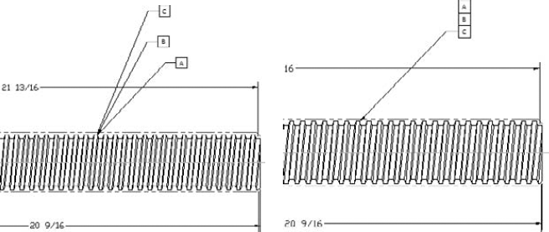
The MLEADERCOLLECT command works only with multileaders that use blocks as their content. The purpose of this command is to group separate leaders into one leader with all the blocks connected. For example, if you are using multileaders to point out objects that need additional annotation, multiple comments might apply to one object. You would then need a multileader that ended with more than one letter or number. Figure 14.26 shows three individual multileaders before and after being collected, using a vertical arrangement.
However, the command also uses the last multileader you choose for its final location (assuming they point to different locations). For example, if you first choose a block labeled 1 and then choose a block labeled 2, the final multileader will point to the location of label 2. If necessary, you can easily move the multileader by using its grips.
At the Select multileaders: prompt, choose the multileaders, taking into account the final order and location you want, as I just described. At the Specify collected multileader location or [Vertical/Horizontal/Wrap]: prompt, specify where the blocks will now appear. You can see a preview as you move the cursor. You can also choose one of the following options:
Vertical. Places the blocks in a vertical line.
Horizontal. Places the blocks in a horizontal line.
Wrap. Lets you specify either a width or a number of blocks. After that, the blocks wrap to the next line.
After you choose an option, the previous prompt repeats. Specify a location for the collected multileader.
Note
The Express Tools include the QLDETACHSET command, which detaches a leader's annotation from the leader line, to create two separate objects. Choose Express Tools tab
Note
The drawing used in the following exercise on drawing multileaders, ab14-e.dwg, is in the Drawings folder on the DVD.
STEPS: Drawing Multileaders
Open
ab14-e.dwgfrom your DVD.Save the file as
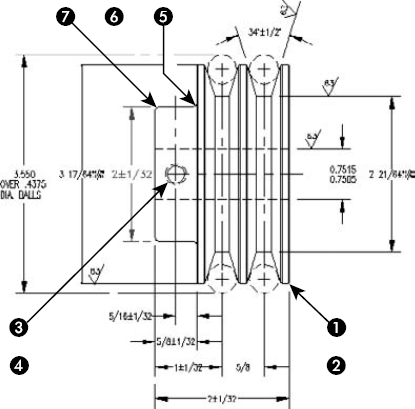
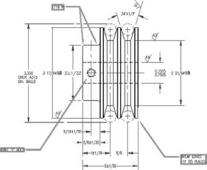
ab14-06.dwgin yourAutoCAD Biblefolder. This is a drawing of a set of pulleys, as shown in Figure 14.27. Object Snap mode should be turned off. Click the Show/Hide Lineweight button on the status bar to turn it on (if necessary).
On the Leader Format tab, choose Green from the Color drop-down list. Choose 0.40 mm from the Lineweight drop-down list.
On the Leader Structure tab, check the Set Landing Distance check box (if necessary) and change the value to 1/2.
On the Content tab, change the Text Style to
DIMTXT. Check the Frame Text check box. Click OK to return to the Multileader Style Manager. The Bold style should be selected. Click Close to return to your drawing. You should see the Bold style displayed in the Multileader Style drop-down list of the Multileaders panel on the Annotate tab.
Follow the prompts:
Specify leader arrowhead location or [leader Landing first/Content first/Options] <Options>:
Pickin Figure 14.27 (near but not on the drawing object). Specify leader landing location:Pick.The In-Place Text Editor opens. EnterBREAK EDGES.EnterTYP (8) PLACES.Click anywhere outside the editor.Repeat the MULTILEADER command. Pick points
Repeat the MULTILEADER command. Pick points

Save your drawing. It should look like Figure 14.28.
Quick Dimension enables you to dimension several objects at one time. You can use Quick Dimension for baseline, continued, and ordinate dimensions. You can also dimension multiple circles and arcs. Later in this chapter, I explain how you can use Quick Dimension to edit dimensions as well. Although Quick Dimension may seem like the answer to all your dimension-related prayers, you can't use it in every case. However, it works well in "mass-production" situations. Dimensions created with the QDIM command are fully associative, so that any changes that you make to objects automatically update their associated dimensions.
Here's how it works, in three easy steps:

At the
Select geometry to dimension:prompt, select all the objects that you want to dimension. You can't use object snaps; you need to select objects. If you select an object in error, type rAt the
Specify dimension line position, or [Continuous/Staggered/ Baseline/Ordinate/Radius/Diameter/datumPoint/Edit/seTtings] <Continuous>:prompt, right-click and choose the type of dimension that you want to create. Figure 14.29 shows a set of continuous dimensions. The Datum Point option sets a new base point for baseline and ordinate dimensions. You can press Enter to use the type of dimension that you just used previously because that shows as the default. The command immediately creates the dimensions for you.
Note
The drawing used in the following exercise on using Quick Dimension to create dimensions, ab14-f.dwg, is in the Drawings folder on the DVD.
STEPS: Using Quick Dimension to Create Dimensions
Open
ab14-f.dwgfrom your DVD.Save the file as
ab14-07.dwgin yourAutoCAD Biblefolder. This is the same drawing that you used in the previous exercise, except that some of the dimensions have been removed (see Figure 14.30). Object Snap mode should be turned off.
Select geometry to dimension:
Pick the circle atin Figure 14.30. Select geometry to dimension:Pick the circle at. Select geometry to dimension:Specify dimension line position, or [Continuous/Staggered/Baseline/Ordinate/Radius/Diameter/datum Point/Edit/seTtings]<Staggered>:
Right-click and choose Radius. Specify dimension line position, or [Continuous/Staggered/Baseline/Ordinate/Radius/Diameter/datum Point/Edit/seTtings] <Radius>:Pick a point on the left circle at about 80 degrees from the right quadrant.Quick Dimension places the radius dimensions.
Repeat the QDIM command. Follow the prompts:
Select geometry to dimension:
Pick the line atin Figure 14.30. Select geometry to dimension:Pick the line at. Select geometry to dimension:Pick the vertical centerline at. Select geometry to dimension:Pick the vertical centerline at. Select geometry to dimension:Pick the line at. Select geometry to dimension:Specify dimension line position, or [Continuous/Staggered/Baseline/Ordinate/Radius/Diameter/datumPoint/Edit/seTtings] <Staggered>:Right-click and choose Baseline. Specify dimension line position, or [Continuous/Staggered/Baseline/Ordinate/Radius/Diameter/datumPoint/Edit/seTtings] <Baseline>:Pick a point below the model.Quick Dimension places the baseline dimensions.
Save your drawing. It should look approximately like Figure 14.31.
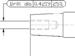
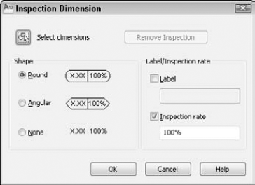
Inspection dimensions specify how often you want the manufacturer of a part to check its measurements, and sometimes to what tolerance. For example, you may want 50 percent of the parts to be checked and require that they be accurate to within
If you haven't already selected a dimension, you can click the Select Dimensions button and do so at this point. In the Shape section, choose the Round, Angular, or None option. In the Label/Inspection Rate section, check the Label check box if you want to add a text label. Then enter the text of the label. The Inspection Rate check box is checked by default. Enter an inspection rate and click OK.
To change the values of an inspection dimension, select it and use the Misc section of the Properties palette.
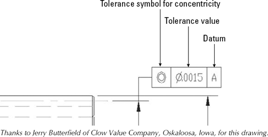
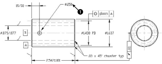
You can use the TOLERANCE command to create geometric tolerances. (For another way to specify tolerances, see Chapter 15.) This command creates feature control frames, which define tolerances. This method of denoting tolerances conforms to international standards such as ISO (International Standards Organization), ANSI (American National Standards Institute), or JIS (Japanese Industrial Standards). Figure 14.34 shows a drawing that uses tolerance feature-control frames.
Creating a tolerance frame is a step-by-step process that depends on what information you want to include. To start the frame, choose Annotate tab
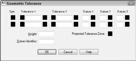
Use this dialog box to build the frame. The frame enables you to create two rows of two tolerances and three datum references (for up to three dimensions), as well as a projected tolerance zone value and a symbol and datum identifier. You'll rarely, if ever, use all the features in the frame.
Follow these steps to build the frame:
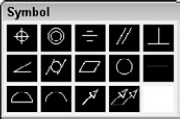
Click the first Sym box to open the Symbol dialog box, as shown in Figure 14.36.
Choose the symbol for the geometric characteristic that you are tolerancing. (Table 14.1 explains these symbols.) If you don't need a symbol, click the blank box. The Symbol dialog box disappears.
To insert a diameter symbol before the first tolerance, click the black Dia box to the left of the text box in the Tolerance 1 section.
Type the tolerance value in the Value box.
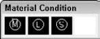
If you want to specify a material condition, click the black MC box to the right of the text box. The Material Condition dialog box opens, as shown in Figure 14.37. Choose the symbol that you want. The dialog box disappears.
If desired, complete a second tolerance.
If desired, type a datum in the Datum box of the Datum 1 section, usually A.
If desired, add a material condition, using the same method described in Step 5.
If desired, type in datum references in the Datum 2 and Datum 3 sections, usually B and C with material conditions.
If you need to specify a projected tolerance zone for a perpendicular part, type a value in the Height box. Then click the Projected Tolerance Zone box to insert the Projected Tolerance Zone symbol.
Finally, if you want to specify a datum identifier, type the identifier letter in the Datum Identifier box.
Click OK to return to your drawing.
If you choose a material condition symbol and then change your mind, click the MC box again and choose the blank square to delete your symbol.
After you complete the frame, you're returned to your drawing with the Enter tolerance location: prompt on the command line. Specify any point to insert the frame.
Tip
You can create a matching Datum reference to place on your model by creating a tolerance frame with no symbol and only the Datum letter.
To edit a geometric tolerance, select it and open the Properties palette. To change the text, click the Text Override item and then click the Ellipsis button at the right. The Geometric Tolerance dialog box opens, and you can make any changes that you need. Click OK to return to your drawing.
Note
The drawing used in the following exercise on creating geometric tolerances, ab14-g.dwg, is in the Drawings folder on the DVD.
STEPS: Creating Geometric Tolerances
Open
ab14-g.dwgfrom your DVD.Save the file as
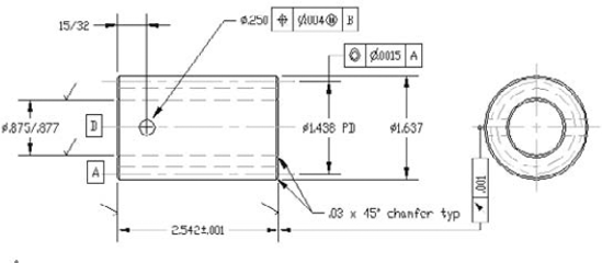
ab14-08.dwgin yourAutoCAD Biblefolder. This drawing of a gear operator is shown in Figure 14.38. The Dim layer is current.Choose Annotate tab
The Symbol dialog box opens. Choose the top-left symbol (for position).
In the Tolerance 1 section of the Geometric Tolerance dialog box, click the next black box, which is the Dia box, to insert the diameter symbol. In the Value box, type .004. Click the next black box, which is the MC box. In the Material Condition dialog box, choose the first image tile (for Maximum material condition).
In the Datum 1 section, type B in the Datum box. Click OK.
At the
Enter tolerance location:prompt, pickSave your drawing. It should look like Figure 14.39.
Dimensions have many properties — text size, arrowhead size, text placement, and so on. You change most of these properties by changing the dimension style — either globally changing all dimensions using that style, or overriding a dimension style setting for a particular dimension. The next chapter covers dimension styles, but here I cover several other ways to edit dimensions.
The DIMASSOC system variable specifies whether dimensions are associative. Here are the settings:
0 creates exploded dimensions. Each part of the dimension is a separate object, and there is no association between the dimension and the object that it dimensions.
1 creates nonassociative dimensions. The dimension is all one object but is not updated if the object that it dimensions is changed.
2 creates associative dimensions. The dimension is all one object and is updated if the object that it dimensions is changed.
Warning
By default, new drawings created in AutoCAD 2010 and AutoCAD LT 2010 are associative. However, drawings created in releases prior to 2002 are not associative. If you open pre-2002 release drawings and save them as 2010 drawings, you should change the DIMASSOC system variable's value to 2.
Use the DIMREASSOCIATE command to associate dimensions with their objects. You need to use this command when you open drawings created in releases prior to 2002 in AutoCAD 2010 or AutoCAD LT 2010. You might also need to use this command when dimensions become disassociated from their objects, perhaps through some editing process, or to reassociate dimensions after you've disassociated them for some reason.
To use DIMREASSOCIATE, follow these steps:

At the
Select objects:prompt, select the dimensions that you want to associate. Press Enter to end object selection.You see a prompt that varies according to the type of dimension you've selected. For example, for linear dimensions, you see the
Specify first extension line origin or [Select object] <next>:prompt. At the same time, you see a marker in the form of an X that corresponds to the prompt, as shown in Figure 14.40. The marker indicates an association point (a point that connects an object and all or part of its dimension). If the X has a box around it, the dimension is already associated with the point marked by the X.Note
If you use the wheel of a mouse to pan or zoom, the X disappears. Press Esc and start the command again or type 'redraw
Use an object snap to specify the location of the X (whether the same location as shown or a different location) or use the Select Object option to select an object (right-click and choose Select Object). To skip to the next prompt without associating the dimension to the marked point, press Enter.
Continue to respond to the prompts in turn. The command prompts you through all the dimensions you selected.
Warning
When specifying object snaps, be careful that you choose the point you want. For example, if you use an endpoint object snap where two lines meet, you cannot be sure of which line's endpoint you've chosen. When you move or stretch the line that you expect to be associated with the dimension, you may find that the dimension doesn't budge. That's because it's actually associated with a different line. Selecting the object itself is often a better solution, because the dimension is associated with the object.
Occasionally, you may want to edit a dimension in such a way that you need to remove its associativity. Perhaps you need to squeeze it into a tight corner. For these times, use the DIMDISASSOCIATE command by typing it on the command line. At the prompt, select the dimensions that you want to disassociate from their objects.
Note
You cannot disassociate dimensions that are on locked layers. Unlock the layer first and then disassociate the dimension.
The DIMREGEN command updates the locations of all associative dimensions. This command, which you type on the command line, is needed only if:
You pan or zoom with a wheel mouse in a paper space layout while model space is active.
You open a drawing containing dimensioned objects that have been edited with a previous release of AutoCAD or AutoCAD LT.
You open a drawing containing external references that are dimensioned in the current drawing, and dimensioned objects in the external reference have been changed.
The DIMEDIT command offers four ways to edit dimensions. The advantage of this command is that you can change more than one dimension at a time. Type dimedit
Home. Moves dimension text to its default position as defined by the dimension style.
New. Lets you type new text to replace the existing text. The In-Place Text Editor opens, showing zeros to represent the dimension text. You can use this option to add a suffix, such as TYP (typical), to several dimensions.
Rotate. Rotates the dimension text. This works like the rotation angle for text.
Oblique. Angles the extension lines of the dimension. Use this when you have several dimensions close together that interfere with each other. Specify the final angle of the extension lines, not the rotation from the current angle.
Note
The Annotate tab
As soon as you choose an option, DIMEDIT prompts you to select objects. You can select as many dimensions as you want. You have the opportunity to use the DIMEDIT command in an exercise after the next section.
The DIMTEDIT command repositions dimension text. To start the command, choose Annotate tab
At the Specify new location for dimension text or [Left/Right/Center/Home/Angle]: prompt, you can use the cursor to pick a text location. You can also right-click and choose one of the options:
Note
The drawing used in the following exercise on using DIMEDIT and DIMTEDIT to edit dimensions, ab14-h.dwg, is in the Drawings folder on the DVD.
STEPS: Using DIMEDIT and DIMTEDIT to Edit Dimensions
Open
ab14-h.dwgfrom your DVD.Save the file as
ab14-09.dwgin yourAutoCAD Biblefolder. This is a civil engineering drawing whose dimensions need some editing (see Figure 14.41).The dimension at

Save your drawing.
Note
The Express Tools command, DIMREASSOC, does the same thing that you accomplished in Step 3 of this exercise — restoring the default measurement value to modified dimension text. Choose Express Tools tab
Sometimes you might want to place an arrow outside the extension line, but facing inward. For example, you might do this in a tight space. Figure 14.42 shows a dimension with a flipped arrow.
To flip an arrow, pick a dimension nearest the arrow that you want to flip. Then right-click and choose Flip Arrow from the shortcut menu. Repeat the process to unflip the arrow.
You can edit dimension text as you would any other multiline text object. Enter ddedit
You can edit dimensions by using the Properties palette just as you can edit the properties of any other object. Select any dimension and open the Properties palette. You see the properties of the dimensions that you can edit. You can also edit dimensions in the Quick Properties panel; however, fewer properties are available.
Many of these settings make more sense after you learn about dimension styles, which are covered in the next chapter. For example, the listings for Primary Units, Alternate Units, Fit, Lines & Arrows, Text, and so on duplicate the tabs in the New Dimension Style and Modify Dimension Style dialog boxes. You can change the color, layer, lineweight, and linetype. To override the automatic dimension text, enter the text in the Text Override field of the Text section of the Properties palette or the Quick Properties palette.
Tip
You can create a background mask like the one that you can create for multiline text. (For more information, see Chapter 13.) If dimension text covers other objects, select the dimension and open the Properties palette (Ctrl+1). Choose a color from the Fill Color drop-down list in the Text section. For the background mask to work, the dimension needs to be on top of any other objects that it overlaps. To bring a dimension to the top, use the TEXTTOFRONT command.
Note
You can convert a dimension to a dimensional constraint. For the complete discussion of constraints, see Chapter 10. Enter dimconstraint
Dimension and multileader styles can be annotative, meaning that they can automatically change scale based on the scale of a viewport on a layout. (I discuss viewports and layouts in Chapter 17.) I've mentioned in this chapter how to make a dimension and multileader style annotative.
You can change the annotative scales of any dimension or multileader that uses an annotative style by using the OBJECTSCALE command. Follow these steps:
Select the dimension or multileader. (You can select more than one.)
Open the Properties palette. In the Misc section, click the Annotative Scale item to display the Ellipsis button.
Click the Ellipsis button to open the Annotation Object Scale dialog box.
To add an annotation scale, click the Add button. Choose a scale from the Add Scales to Object dialog box and click OK.
To delete an annotation scale, select it and click the Delete button.
Click OK.
Tip
You can also select one or more annotative objects, right-click in the drawing area, and choose Annotative Object Scale.
Sometimes, after you've created a number of linear or angular dimensions, you realize that they would look neater if they were equally spaced apart from each other. Rather than re-create or move them, you can use the DIMSPACE command to space existing dimensions. You can let the command determine the spacing automatically, or you can specify a spacing.
In order for this command to work, the dimensions must meet the following conditions:
They must be linear or angular dimensions.
They must be in a group of the same kind of dimension. For example, you might have all linear dimensions. If one is rotated, they must all be rotated; if one is aligned, they must all be aligned.
The dimensions must be parallel (for linear) or concentric (for angular).
The dimensions must share an extension line.
At the Enter value or [Auto] <Auto>: prompt, enter a spacing or use the Auto option to let the command figure out the spacing itself. You can use a value of 0 to align the dimensions along the same horizontal or vertical line.
It's not good form for dimensions to cross other dimensions or objects. Many disciplines break a dimension or extension line where it crosses an object with a small space. This gives the appearance that the object is in front of the dimension. You can break dimensions or multileaders by using the DIMBREAK command.
The great feature of DIMBREAK is that if you move the object to another location where it still crosses the dimension, the break moves accordingly.
You can use the Manual option to specify two points on the dimension line or extension line. In this way, you can set the size of the break yourself. However, if you use the Manual option, the break does not update if you move the crossing object.
Use the Multiple option at the first prompt to create breaks in more than one dimension at a time. You then select the dimensions. At the Select object to break dimensions or [Auto/Remove] <Auto>: prompt, choose the Auto option so that you can break all the dimensions.
If you want to remove an existing break, use the Remove option.
You can set a break size when you create a dimension or multileader style. For dimensions, use the Break Size text box on the Symbols and Arrows tab of the Modify Dimension Style dialog box. For Multileaders, use the Break Size text box on the Leader Format tab of the Modify Multileader Style dialog box.
You can also use Quick Dimension in AutoCAD (but not AutoCAD LT) to edit dimensions, whether created with QDIM or some other dimensioning command. When you select the geometry and dimensions you want to edit, you see an X at each eligible edit point, as shown in Figure 14.43.
Here's what you can do with QDIM:
You can join two dimensions by removing the edit points between them.
You can split a dimension into two dimensions by adding edit points within the existing dimension.
You can move the dimension line.
You can change the type of dimension.
Warning
Editing with QDIM works best when the geometry is simple. Unless you can select only the geometry and dimensions that you want to work with, you'll end up changing dimensions that you don't want to edit.
To edit dimensions with QDIM, follow these steps:

At the
Select geometry to dimension:prompt, select the geometry and the dimensions that you want to edit.At the
Specify dimension line position, or [Continuous/Staggered/ Baseline/Ordinate/Radius/Diameter/datumPoint/Edit/seTtings] <Continuous>:prompt, right-click and choose Edit. You see a cross at each eligible edit point.At the
Indicate dimension point to remove, or [Add/eXit] <eXit>:prompt, you can:Select the points of the dimensions you want to remove. If you see two possible edit points in line with each other that could be creating the dimension you want to remove, select both of them.
Right-click and choose Add. Use object snaps to add one or more points.
Right-click and choose Exit to continue with the command.
At the
Specify dimension line position, or [Continuous/Staggered/ Baseline/Ordinate/Radius/Diameter/datumPoint/Edit/seTtings] <Continuous>:prompt, right-click and choose an option if you want to change the type of dimension.The prompt repeats. Pick a location for the new set of dimensions.
Press Enter to end the command and update the dimensions.
Grips are ideal for moving dimension lines and text. The grips at the dimension line endpoints and the text insertion point are quite useful for making adjustments in dimensions. (I discuss grip editing in Chapter 10.)
To move a dimension line closer or farther from the dimensioned object, pick the dimension to display the grips. Pick one of the grips at the endpoints of the dimension line to highlight it. The Specify stretch point or [Base point/Copy/ Undo/eXit]: prompt appears. Drag the dimension line to the desired location. Press Esc to remove the grips.
To move dimension text, pick the dimension to display the grips. Pick the grip on the dimension text to highlight it. Drag the dimension text to its desired location.
Tip
For best results, turn Ortho mode on while trying to drag the dimension line or the dimension text. Polar tracking also works well.
You can also grip-edit multileaders in the same way. These also have two triangular grips that you can use to change the length of the landing line.
Because dimensions are associative, when you edit objects, the dimensions automatically adjust to the new object measurements. Stretching the object with the STRETCH command or grips is usually the best way to accomplish this. The object and the dimension adjust at the same time.
Note
The drawing in the following exercise on using DDEDIT, QDIM, grips, and STRETCH to edit dimensions, ab14-i.dwg, is in the Drawings folder on the DVD.
STEPS: Using DDEDIT, QDIM, Grips, and STRETCH to Edit Dimensions
Open
ab14-i.dwgfrom your DVD.Save the file as
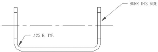
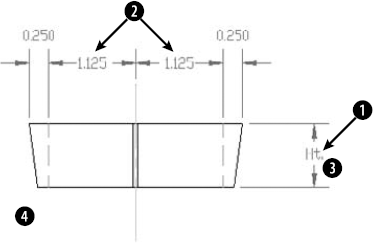
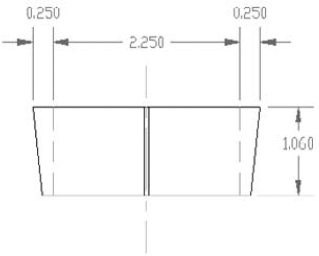
ab14-10.dwgin yourAutoCAD Biblefolder. This is a cross-section of a valve part, as shown in Figure 14.44.To replace the dimension marked Ht., type ddedit

Pick the dimension at
Choose Home tab
Select objects:
Pick at. Specify opposite corner:Pick at. 9 found Select objects:Specify base point or [Displacement] <Displacement>:0,−.25Specify second point or <use first point as displacement>:The valve part stretches, and the dimension that measures its height changes accordingly.
Save your drawing. It should look like Figure 14.45.
The dimension features in AutoCAD and AutoCAD LT enable you to dimension almost anything. In this chapter, you read about:
Creating linear, radial, dimension, angular, and ordinate dimensions
Formatting and creating multileaders
Dimensioning with the Quick Dimension feature, available in AutoCAD only
Creating inspection dimensions
Creating tolerances
Editing dimensions
In the next chapter, I continue the subject of dimensions by explaining how to gain total control with dimension styles.