
Until you learn about layers, you draw everything in black or white. Drawing everything in one color is not a very good way to draw — besides, it's boring! If everything is the same color, it's hard to distinguish the various elements of a drawing. If you've followed the exercises throughout this book, you've opened some drawings from the DVD that used various colors and linetypes (such as dashed lines). For example, in some of the architectural drawings, you may have noticed that the walls are a different color than the fixtures in the kitchen. When you create text and dimensions, covered in Chapters 13, 14, and 15, you almost always use a color that stands out from the main model that you're drawing. You can also create objects with varying line widths, called lineweights. This use of color, linetype, and lineweight helps to organize your drawings, making them easier to understand.
Most often, you assign color, linetype, and lineweight to a layer. A layer is simply an organizational tool that lets you organize the display of objects in your drawing. Every object must be on a layer, and every layer must have a color, a linetype, and a lineweight. You define layers to meet your drawing needs. Layers, colors, linetypes, and lineweights are called object properties. You can easily change any object's properties. This chapter explains how to create and change these object properties to organize your drawing.
Layers offer powerful features that enable you to distinguish all the various elements of your drawing. In an architectural drawing, for example, common layers are walls, doors, windows, plumbing, electrical fixtures, structural elements, notes (text), dimensions, and so on. Mechanical drawings might use center, hidden, hatch, object, and titleblock layers. Each discipline has its own conventions, and where you work you might have specific conventions that you must follow.
Creating layers is an important part of setting up a drawing, in addition to the setup features covered in Chapter 5. You should create and save layers in your templates so that they're available to you when you start to draw. Layers give you many ways to organize your drawing. For example, you can:
Assign different colors, linetypes, and lineweights to layers.
Assign the various colors to different pens in a pen plotter, resulting in a paper drawing with varying colors or line widths.
Control the visibility of layers. Making a layer invisible lets you focus on just the objects that you need to draw or edit.
Control which objects are plotted.
Lock a layer so that objects on that layer cannot be edited.
Note
You can also assign a plot style to a layer. A plot style is a group of settings that affects how your drawing is plotted. Chapter 17 covers plot styles.
Besides having a color, linetype, and lineweight, every layer must have a name. All drawings come with a default layer, called layer 0 (zero). Its color is black/white (depending on the background color of the drawing area), its linetype is Continuous, and its lineweight is Default. (The lineweight for Default is 0.010 inch or 0.25 mm.) Most of the exercises in this book up to this point have used layer 0. To create a new layer, you must give it a name, a color, a linetype, and a lineweight. You can then start drawing on that layer.
Layers have four states. These states control visibility, regeneration, editability, and plottability of layers:
On/Off. On layers (the default) are visible. Off layers are invisible and are regenerated with the drawing. Off layers are not plotted.
Thawed/Frozen. Thawed layers (the default) are visible. Frozen layers are invisible and are not regenerated with the drawing. However, when you thaw a frozen layer, the drawing regenerates. If you have floating viewports (covered in Chapter 17), you can also freeze a layer just in the current viewport, or only for new viewports that you create. You can also create a layer that is frozen in all viewports. Frozen layers are not plotted.
Unlocked/Locked. Unlocked layers (the default) are visible and editable. Locked layers are visible but cannot be edited.
Plottable/Not Plottable. Plottable layers are plotted. Not plottable layers are not plotted. This setting affects only layers that are on or thawed, because off and frozen layers are not plotted anyway.
Note
The Layer Properties Manager is a palette that you can auto-hide and dock. Changes that you make to layer properties and states in the palette apply immediately in your drawing.
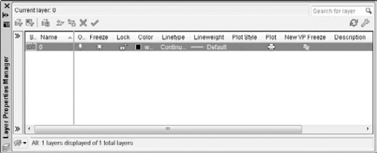
Table 11.1 explains the columns in the palette. For a description of the icons in most of the columns, see Table 11.2, later in this chapter.
Table 11.1. Columns in the Layer Properties Manager
Column Name | Description |
|---|---|
Status | The status of each layer. A darker layer icon is used, and a lighter icon is unused. The current layer shows a checkmark. |
Name | The name of the layer. To change the layer, click once to display a border and click again to type a new name. |
On | The current on/off state of a layer. Click to turn the layer on or off. |
Freeze | The current freeze/thaw state of a layer. Click to freeze or thaw a layer. |
Lock | The current locked/unlocked state of a layer. Click to lock or unlock a layer. |
Color | The current color of the layer. Click to change the color. |
Linetype | The current linetype of the layer. Click to change the linetype. |
Lineweight | The current lineweight of the layer. Click to choose a new lineweight. |
Plot Style | The current plot style of the layer. Click to select a new plot style. (Chapter 17 covers plot styles.) |
Plot | The current plottable/not plottable state of the layer. Click to make the layer plottable or not plottable. |
Current VP Freeze | The freeze/thaw state of the layer in the current floating viewport. Click to freeze or thaw the layer in active floating viewports. This column is displayed only if you have floating viewports and a layout tab is active. (Chapter 17 covers floating viewports.) |
New VP Freeze | The current freeze/thaw state of the layer in new floating viewports that you create. Click to freeze or thaw the layer in new viewports. This column is displayed only if you have floating viewports and a layout tab is active. (Chapter 17 covers floating viewports.) |
Description | A place to enter a description of a layer. |
Note
When you open the Layer Properties Manager with a layout active, four additional columns appear that let you override layer properties for specific viewports. I explain this feature in more detail in Chapter 17.
To adjust the display in the Layer Properties Manager, you can do the following:
Display or hide the Filters pane by clicking the double-arrow icon at the top of that pane.
Change the width of any column in the Layer Properties Manager by placing the cursor over the line dividing two column headings and dragging.
Double-click the line dividing two columns to minimize/maximize the column width.
Click any column head to sort the layers by that column. Click again to sort in the opposite order.
Right-click any heading and display a shortcut menu where you can choose which columns you want to see.
Drag any column to any location to specify the order of the columns.
Right-click any heading and choose Freeze or Unfreeze Column (depending on the current status). Freezing a column forces it to the left of a gray, vertical line and holds it visible, even if you scroll to the right.
Resize the entire dialog box by dragging on any side.
Note
Next to the New Layer button is the New Layer VP Frozen in All Viewports button for creating a layer that is frozen in all viewports. I discuss freezing layers in viewports in Chapter 17.
Tip
If you want a new layer to have the same color and/or linetype as an existing layer, choose that existing layer and click New. The new layer inherits the properties of the selected layer. You can then make any changes that you want.
Layer names can be up to 255 characters long and may include spaces. Layer names retain the uppercase/lowercase characters that you type. Layer names may not include the following symbols: < > / " ; ? * | , =`.
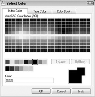
To change the default color, move the cursor to the color box in the same row as the new layer. Click to open the Select Color dialog box, shown in Figure 11.2, with the Index Color tab displayed.
Click the color that you want. At the bottom of the dialog box, the color's name or number appears along with a sample of the color. Click OK to close the dialog box and return to the Layer Properties Manager.
Note that the Index Color tab offers you a choice of standard colors, gray shades, and a fuller palette of colors. The standard colors are the original colors that AutoCAD (and then AutoCAD LT) offered, and they're the ones often used, even today. These colors have both a name and a number, whereas other colors have only a number (an index). The standard colors are red (1), yellow (2), green (3), cyan (4), blue (5), magenta (6), and white (7).
Note
You can choose any color you want for the background color of a drawing, but commonly it is a black, white, or off-white screen. The default screen is off-white and the default color for 7 is black, but the color is called white. When you work on a black screen, objects using the color of 7 appear white (or else they would be invisible) and vice versa. To change the screen color, choose Application Button
Note
When selecting a color on the Index Color tab, the arrow cursor and highlighting make it easier to see which color swatch you are about to select.
For more color choices, click the True Color tab, as shown in Figure 11.3.
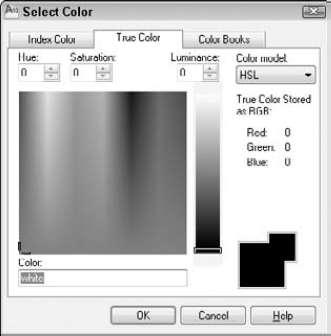
Figure 11.3. The True Color tab of the Select Color dialog box offers a more precise way to define color.
To define a color, first choose the color model from the Color Model drop-down list. You have two choices:
HSL (Hue, Saturation, Luminance). Hue is the actual wavelength of light that defines the color. Saturation is the purity or intensity of the color. Luminance is the brightness of the color.
RGB (Red, Green, Blue). Defines a color according to the intensity of red, green, and blue in the color.
If you choose the HSL color model, specify the color as follows:
Specify the hue by dragging the crosshairs horizontally across the colors, or type a value from 0° to 360° in the Hue text box.
Specify the saturation by dragging the crosshairs vertically over the colors, or type a value from 0% to 100% in the Saturation text box.
Specify the luminance by dragging the bar on the color slider, or type a value from 0% to 100% in the Luminance text box.
Note
When you define a color by using the HSL color model, you also see the RGB values displayed in the Select Color dialog box.
If you choose the RGB color model, specify the red color by dragging the color bar, or type a value from 1 to 255 in the Red text box. Do the same for the green and blue color values.
You can also choose a color by using the Color Books tab, as shown in Figure 11.4.

The Color Books tab displays colors in color books. Color books are files that define colors. AutoCAD includes several Pantone color books. Pantone is a commonly used system of matching colors that is often used for printing on paper and fabric.
To use a color from a color book, follow these steps:
On the Color Books tab of the Select Color dialog box, choose a color book from the Color Book drop-down list.
Drag the color slider or use the up and down arrows to choose a "page" of the color book. On the left, you see the colors for that page. A page can hold up to ten colors.
Choose one of the colors on the left side of the dialog box.
Click OK.
The default linetype is a continuous line, but you can also use many other linetypes. These linetypes are repeating patterns of dashes and/or dots and spaces, although they can also include text and shapes. Linetypes are covered more fully later in this chapter.
To change the default linetype, move the cursor to the linetype in the new layer's row. Click to open the Select Linetype dialog box, as shown in Figure 11.5.
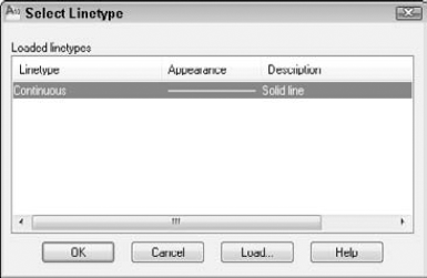
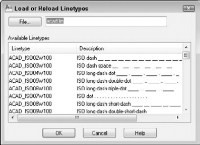
If the linetype that you want appears on the list, click the linetype and choose OK to close the dialog box. If the linetype does not appear, you need to load the linetype. Click Load to open the Load or Reload Linetypes dialog box, as shown in Figure 11.6.
Linetypes are stored in text (ASCII) files with the filename extension LIN. The standard linetypes are in acad.lin in AutoCAD and in acadlt.lin in AutoCAD LT. You can create your own linetypes and store them in these files. You can also store them in another file that you create with the extension .lin. Click File at the top of the dialog box if you want to load a linetype from a file that you created. Choose the linetype file that you want to load and click Open.
Note
See Chapter 31 for a full discussion of creating your own linetypes.
As soon as you load a linetype and click OK, you return to the Select Linetype dialog box. The loaded linetype now appears on the list. Choose it and click OK. You're now back in the Layer Properties Manager dialog box.
To set a lineweight for a layer, click the Lineweight column of that layer to open the Lineweight dialog box, as shown in Figure 11.7. Choose a lineweight and click OK.
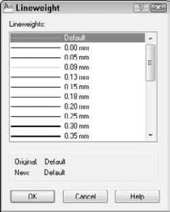
Figure 11.7. When you click the Lineweight column of the Layer Properties Manager, the Lineweight dialog box opens so that you can choose a lineweight.
Lineweights have the following features:
The default lineweight value for layers and objects is called DEFAULT, which has a value of 0.010 inch or 0.25 mm.
On the Model tab, where you draw, lineweights are displayed in relation to pixels, the unit of measurement for computer screens. A lineweight of 0 is displayed with a width of 1 pixel. Wider lineweights are calculated proportionally to the actual width of the lineweight. The lineweight display on the Model tab does not change as you zoom in or out.
On Layout tabs (covered in Chapter 17), lineweights are displayed in real-world units as they will be plotted. Lineweights act like other objects in your drawing and look bigger or smaller as you zoom in and out.
By default, lineweights are measured in millimeters. You can format lineweights by choosing Home tab

If you don't want to use lineweights, you can just ignore them and display every object by using the default lineweight.
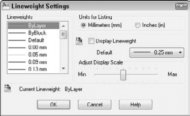
Figure 11.8. The Lineweight Settings dialog box lets you format how lineweights are measured and displayed.
After you've set your new layer's color, linetype, and lineweight in the Layer Properties Manager, you're ready to use the layer.
Note
Many people have CAD standards that restrict which layers should be in a drawing. You can specify that you want to receive a notification whenever a new layer is added to a drawing. Then you can decide if the layer meets your CAD standards. For more information, see Chapter 26, where I cover CAD standards.
Note
The drawing used in the following exercise on creating layers, ab11-a.dwg, is in the Drawings folder on the DVD.
Open
ab11-a.dwgfrom the DVD.Save the file as
ab11-01.dwgin yourAutoCAD Biblefolder.

Click the color square in the Color column to open the Select Color dialog box. Choose the blue square from the Standard Colors and click OK.
Choose the New Layer icon again to create another new layer. Type Hidden

Click the color square in the Color column to open the Select Color dialog box.
In the Select Color dialog box, click the True Color tab. From the Color Model drop-down list, choose RGB. In the Color text box, type 141,218,189. (In some instances, you may have to re-choose RGB from the Color Model drop-down list to make the Color text box active.) Press Tab. You should see a teal (blue-green) color. Click OK.
In the main layer listing, click Continuous in the same row as the Hidden layer to open the Select Linetype dialog box. Click Load to open the Load or Reload Linetypes dialog box. Scroll down until you see the HIDDEN linetype. Choose it and click OK. In the Select Linetype dialog box, choose HIDDEN and click OK.
Click the Description column for the Hidden layer. (If you can't see this column, which is usually the rightmost column, drag the edge of the palette that is opposite the title bar to widen the palette. Click again so that a text cursor appears. Type teal, hidden lines
Close or auto-hide the palette.
Choose Home tab
Save your drawing.
Note
Layerhtm Displays a copy of the Layer Properties Manager dialog box in your browser so that you can print it. Look in SoftwareChapter11layerhtm.zip folder on the DVD.
After you have the layers you need, you need to switch from layer to layer as you draw. To do so, choose Home tab
The Layer Control window has three display modes:
If no object is selected, it displays the current layer.
If one or more objects are selected, it displays the layer of the selected object(s).
When objects on varying layers are selected, the Layer Control list goes blank, indicating that more than one layer is included in the selection.
To check the current layer, make sure that no object is selected. If necessary, press Esc to deselect any objects.
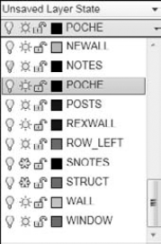
To open the Layer Control drop-down list, click its down arrow. You see a list of all of your layers, including their states and colors. When you pass the mouse over the items, a tooltip tells you what they mean. The Layer Control drop-down list has three functions:
To switch the current layer, make sure that no object is currently selected, click the Layer Control drop-down list arrow, and click the name of the layer that you want to be current. Be careful to click only the name — otherwise, you may change the layer's state. After you click a new layer name, the drop-down list automatically closes.
After you create a layer, you can manage that layer — and all the objects on that layer — by changing its states. You can change some layer states through the Layer Control drop-down list; others must be changed in the Layer Properties Manager. Each layer state has different properties and uses:
On/Off. Turn layers off when objects on those layers interfere with the drawing process. For example, if you want to edit only objects on your Object layer, but objects exist on other layers nearby, you can turn off the other layers and easily select the objects on the Object layer with a window. Then turn the other layers back on. The on/off state is available on the Layer Control drop-down list.
Thaw/Freeze. You can freeze layers for reasons similar to those that lead you to turn off layers. In general, freeze layers when you want to work without those layers for a longer period of time. The thawed/frozen state is available on the Layer Control drop-down list.
Thaw/Freeze in Current Viewport. You may want to freeze or thaw layers in some floating viewports but not in others. For example, if you want to display dimensions in one viewport but not in others, freeze your dimensions layer in all the viewports except one. You can change this state on the Layer Control drop-down list if you're working on a layout. You can also click the Current Viewport Freeze icon in the Layer Properties Manager.
Thaw/Freeze in New Viewports. You can also freeze or thaw layers in future viewports that you create. For example, after you display dimensions or text in one viewport, you may want to make sure that they won't appear in any new viewports that you create. This state is available in the New Viewport Freeze column of the Layer Properties Manager. (I cover floating viewports in Chapter 17.)
Note
When you make several layer property changes in a row and then undo them, AutoCAD and AutoCAD LT count these changes as one change. Therefore, Undo brings you back to the state before the first change. You can change this behavior by choosing Application Button
Unlock/Lock. Lock a layer when you want to ensure that objects on that layer are not changed. You can still use objects on locked layers for reference (for example, you can use their object snaps). Click the Lock/Unlock icon on the Layer Control drop-down list.
Note
When you select an object on a locked layer, it doesn't display grips, because you can't edit it.
Plot/No Plot. Make a layer not plottable when you want to create reference text or revision marks on your drawing but don't want to plot them. You may also have a drawing that contains both actual and planned structures; this feature enables you to plot showing only the actual structures. Being able to change a layer's plottable state makes it possible for you to create variations on your drawing, perhaps for different users, such as electricians, plumbers, and roofers. The plot/no plot state is available in the Plot column of the Layer Properties Manager.
Tip
Both the off and frozen states make layers invisible. The purpose of the frozen/thawed layer states is to reduce regeneration time — this is the main difference between On/Off and Thawed/Frozen layer visibility options. However, today's computers are faster, and recent releases of the software have reduced the need for regeneration. Because thawing a layer causes a regeneration, whereas turning a layer back on only causes a redraw, you actually save a regeneration by using On/Off rather than Thawed/Frozen.
Click any of the state icons to toggle a layer's state. For example, if you want to freeze a layer, click its sun icon; it switches to a snowflake icon. Table 11.2 shows the icons for each state.
When you change a layer's state from the ribbon, the drop-down list stays open so that you can change the state of more than one layer at a time. Click the top of the list to close it.
Warning
Be careful when editing a drawing with frozen or off layers — it's easy to forget about them. For example, you could move a whole section of your drawing and inadvertently leave the frozen objects in that section behind.
Often you work with sets of layer states. For example, you may lock certain layers during part of the editing process to avoid changing objects on those layers. You may also set some layers as not plottable just before final plotting, but want them plotted for a draft plot. You may also want to temporarily change the properties of certain layers — color, linetype, lineweight, and plot style — and then change them back.
You could spend a lot of time adjusting all these layer states and properties. Instead, you can save and restore sets of layer states — the properties and states of all the layers in a drawing. You can save layer states to automate the process of restoring layer states and properties by saving the set of all layer states and properties. After you save this set, you can restore it at any time. The term layer states includes the set of all layer states as well as their properties.
You can also export layer state settings to a file. You can then use the layer-state settings in another drawing with the same or similar layers.
To save a layer state, follow these steps:
Set all the layer states and properties the way you want them. Usually, you've already done this and should save the state before making changes that you plan to reverse later on.

Click New and type a name for your layer state in the New Layer State Name text box of the New Layer State to Save dialog box. If you want, type a description. Click OK.
Back in the Layer States Manager, choose the layer states and properties that you want to save in the Layer Properties to Restore section. (If you don't see this section, click the More Restore Options arrow button at the lower-right corner of the dialog box.)
Warning
States and properties that you do not save are not affected later when you restore the layer state. For example, if you save only the on/off state and then change both a layer's on/off state and its color, when you restore the layer state, only the on/off state is returned to its original setting; the layer retains its new color.
If you want your drawing to look exactly as it did when you saved the layer state (in terms of layers), check the Turn Off Layers Not Found in Layer State check box. Any new layers that you create after saving the layer state are then turned off when you restore your layer state.
Click Close.
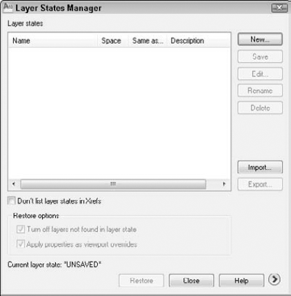
The Layer States Manager enables you to manage layer states in the following ways:
Restore. Click the Restore button to restore a saved layer state.
Import. Click Import to import a layer state that has been previously exported as an
.lasfile. Importing a layer state gives you access to layer states that others have saved. Click Import to open the Import Layer State dialog box.Note
You can import a layer state from a DWG (drawing), DWT (template), or DWS (standards) file. (Standards files are covered in Chapter 26.) In the Import Layer States dialog box, choose the type of file you want from the Files of Type drop-down list. Also, the Layer States Manager includes layer states from xrefs. (See Chapter 19 for information about xrefs.)
Export. Click Export to export the settings of a layer state in an LAS file. Exporting a layer state gives others access to your layer-state settings.
You can choose which properties and states you want to restore. If necessary, click the More Restore Options arrow button to expand the Layer States Manager. Then check or uncheck any of the property and states check boxes. To rename a layer state, click its name, type a new name, and press Enter. After you finish using the Layer States Manager, click Close to close the dialog box.
Sometimes you need to change the layer of an object or objects that you've already drawn. You can do this easily by selecting one or more objects and clicking the layer name that you want for the object in the Layer Control drop-down list (from the Layers panel of the Home tab). The list automatically closes.
Note
If you turn off Noun/verb selection, as I explain in Chapter 9, you cannot select an object and change its layer from the Layer Control drop-down list. Instead, you can change the layer in the Properties palette.
You can also change an object's layer in the Quick Properties panel or the Properties palette. The Quick Properties panel opens automatically (by default) when you select an object. To use the Properties palette, choose View tab
Warning
It's easy to inadvertently change an object's layer. Make sure that objects are not selected (press Esc) if you're about to use the Layer Control drop-down list just to change the current layer.
A set of layer tools that were once in the Express Tools collection are very helpful for working with layers. Table 11.3 lists the Layer tools and what they do.
Table 11.3. Layer Tools
Layer Tool Name | Menu | Description |
|---|---|---|
| Home tab | A full-featured command that helps you to see which objects are on which layers. Using the dialog box and the shortcut menu, you can list the number of objects on each layer, count the total number of layers, save layer states, and purge unused layers. |
| Home tab | Changes the layer of selected objects to match that of another selected object. |
| Home tab | Changes the selected object's layer to the current layer. |
| Home tab | Copies objects while changing the copy to the layer that you specify. |
Home tab | Turns off all layers except the layer of an object that you select, to isolate a specific layer. You can lock and fade layers. (I explain this command further after this table.) | |
| Home tab | Restores the state of layers that existed before you used LAYISO. (I explain this command further after this table.) |
| Home tab | Freezes all layers except the layer of an object that you select in all viewports except the current one, isolating the selected layer in the current viewport. (See Chapter 17 for information on viewports.) |
| Home tab | Turns the layer of the selected object(s) off. |
| Home tab | Turns all layers on. |
| Home tab | Freezes the layer of the selected object(s). |
| Home tab | Thaws all layers. |
| Home tab | Locks the layer of the selected object(s). |
| Home tab | Unlocks all layers. |
| Home tab | Changes the layer of all objects on the first layer selected to the second layer selected. The first layer is purged. |
| Home tab | Deletes objects from the specified layer and purges that layer. |
The LAYISO command can lock layers (other than the one you're isolating) and fade those layers instead of turning them off. The default is to lock layers and fade them by 50 percent. You can change the default by using the Settings option. For example, you can choose to turn off the layers or change the fade percentage. Use the LAYUNISO command to unisolate layers. Choose Home tab
Note
The drawing used in the following exercise on working with layers, ab11-b.dwg, is in the Drawings folder on the DVD.
STEPS: Working with Layers
Open
ab11-b.dwgfrom the DVD.Save the file as
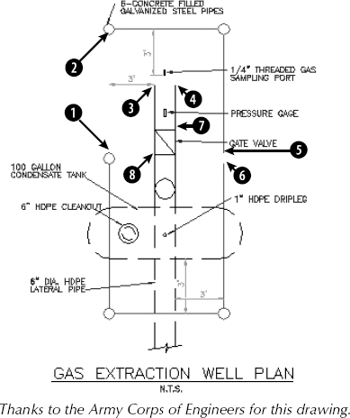
ab11-02.dwgin yourAutoCAD Biblefolder. This drawing is shown in Figure 11.11. The current layer is 0. Make sure that Object Snap is on. Set running object snaps for Endpoint and Quadrant.From Home tab
Start the LINE command. Draw a line from

Click the Layer Control drop-down list and click Object to change the current layer to Object.

Start the CIRCLE command. Right-click and choose
2pto use the two-point option. Draw a circle from the endpoint of
Without changing the layer, start the CIRCLE command and again use the
2poption. Draw a circle between the endpoints at
The last circle was drawn on the wrong layer. To change its layer, select the circle. Then click the Layer Control drop-down list and choose Pipes. Press Esc to remove the grips and see the result. The circle is now on the Pipes layer. Notice that the current layer is still Object in the Layer Control display.


If you have AutoCAD. Click Home tab
If you have AutoCAD LT. Click the Layer Control drop-down list and click Object.
Draw a line from the endpoint at

Pick any text to see what layer it is on. The Layer Control drop-down list changes to show the Text layer. Press Esc to deselect the text. Now choose the words GAS EXTRACTION WELL PLAN at the bottom of the drawing. Click the Layer Control drop-down list and choose Text. Press Esc to remove the grips.
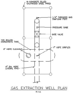
Save your drawing. It should look like Figure 11.12.
Sometimes you need to change the properties of a layer, such as its color or linetype. Changing a layer's properties is a powerful tool because every object on that layer is automatically regenerated with the new properties. Other layer housekeeping tasks are renaming and deleting layers. You use the Layer Properties Manager for these functions.
If you have many layers in a drawing, sorting can help you find the layers on which you need to work. You can sort the layer listing in a drawing by any column, by clicking once on the column title. Click again to see the list in reverse order. Long layer names display a tooltip with the entire layer name.
Note
If sorting by layer name does not appear to be working, increase the value for the MAXSORT system variable, which determines the maximum number of symbols that AutoCAD or AutoCAD LT sorts. Type maxsort
You can change the order of the columns by dragging them. For example, you may want to place the Color column next to the Name column. You can also choose which columns appear in the Layer Properties Manager. Right-click any column name and uncheck any column that you don't want to see. This choice remains until you change it. If you want to see a column again, right-click a column name again and check that column. As mentioned earlier in this chapter, you can freeze certain columns so that they always appear to the left, even if you scroll to the right. Right-click a column name and choose Freeze Column.
Some complex drawings may have dozens of layers, and you may have a hard time finding the layer that you want in the Layer Properties Manager. You can filter the layer list so that you only see the layers that you want. This makes it easy to change a group of layers at once. The Filter Tree panel on the left side of the Layer Properties Manager contains one filter, All Used Layers, as well as the default that displays all layers. To display only used layers, click the All Used Layers filter in the Filter Tree panel.
Note
If you don't see the Filter Tree panel, right-click in the Layer Properties Manager and choose Show Filter Tree or click the double arrow on the left side of the palette.
You can create your own filters. There are two types of filters:
Properties filter. Defines a filter by the properties of the layer. For example, you can create a filter that displays only green layers or layers that start with the letter A.
Group filter. Defines a filter by selecting layers that go into a filter. A group filter offers complete flexibility to filter layers. For example, you might want to create a group filter that contains all your text, annotation, and dimension layers.
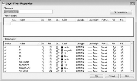
Name the filter in the Filter name text box. To choose a property, click in that property's column. Then do one of the following:
If a drop-down arrow appears, click the arrow and choose one of the options from the drop-down list. (To remove a property, choose the blank line at the top of the drop-down list.)
If an ellipsis button appears, click the button and choose a property from the dialog box that opens. For example, you can choose a layer color from the Select Color dialog box. (To remove a property, select the text, press Del, and click anywhere outside the column.)
To specify a filter for a named property, such as the name or linetype of a layer, you can use wildcards. The two most common wildcard characters are
*(asterisk), which replaces any number of characters, and?, which replaces any single character. For example, you could set the layer name filter toh*and the color to magenta. The resulting filter would include only magenta layers whose names start with the letter H.
As you work, the Filter Preview pane shows the results of your filter. When you're done, click OK. The Layer Properties Manager now shows only the layers that match your filter specifications.
Tip
To add layers by selecting objects that are on the layers you want, right-click the filter and choose Select Layers
Tip
When you work with a large number of layers, think carefully about how you name them. Naming layers in groups is common. For example, if you have several text layers, you could name them Text Title, Text Notes, and Text Schedule. A systematic layer-naming scheme makes it easy to filter the layers that you need, which in turn makes it easy to make changes to groups of layers.
You can modify the color of a layer. To do so, open the Layer Properties Manager, and choose the color swatch of the layer that you want to modify. The Select Color dialog box opens. Choose a color and click OK. For more information about choosing colors, see the section, "Assigning a color," earlier in this chapter.
To change a layer's linetype, click the layer's linetype in the Layer Properties Manager. If you need to choose a linetype that is not on the list, click the linetype of the layer to open the Select Linetype dialog box. There you can either choose a loaded linetype or load a linetype if necessary.
To change a layer's lineweight, click the lineweight for any layer. Choose a new lineweight from the Lineweight dialog box.
Tip
You can modify more than one layer at a time. In the Layer Properties Manager, right-click and choose Select All to choose all the layers. Choose Clear All to deselect all the layers. You can choose a range of layers by clicking the first layer in the range, pressing Shift, and clicking the last layer in the range. Finally, you can choose individual layers by pressing Ctrl for each additional layer. Changes that you make to color, linetype, or lineweight affect all the selected layers.
Note
When you're ready to lay out a drawing for plotting, you generally work on a layout and create floating viewports. You can change the properties of a layer in a viewport. For example, you might want a layer to appear in a different color when you display it in a small detail view from the color that you want in a larger context. For more information, see Chapter 17 where I cover overriding layer properties for layouts and viewports.
Thinking out your layer-naming scheme in advance is best. Many disciplines and organizations have layer-naming standards. However, sometimes you simply need to rename a layer.
To rename a layer, open the Layer Properties Manager. Click the name of the layer, and then click a second time. A border appears, and the name is highlighted. Type the new name and press Enter. Alternatively, you can right-click the layer name and choose Rename Layer from the shortcut menu or just press F2.
Note
You cannot rename layer 0. Layer 0 is the default layer and always remains the same. You can set CAD standards that allow you to check for nonstandard layer names. For more information, see Chapter 26.
Note
You cannot delete the current layer or any layer that has objects on it. (Where would those objects go?) You also cannot delete layer 0, which is the default layer. Finally, you cannot delete layers from external references (covered in Chapter 19). However, the LAYDEL command deletes all objects on a layer and purges the layer.
Layer and linetype definitions add to the size of your drawing because they're kept in the drawing's database. Therefore, eliminating layers and linetypes that you aren't using is worthwhile. You can delete them, but sometimes it's hard to know which layers contain no objects. The PURGE command lets you delete many types of unused definitions, including layers and linetypes.
Note
The Incremental Save Percentage option may prevent a purge during a drawing session from removing all unreferenced layers or linetypes from the drawing. To avoid this, you can either set incremental save to zero, or save the drawing and re-open it and then immediately use the PURGE command. To set this option, choose Application Button
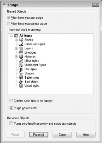
At the top of the dialog box, you can choose to view objects that you can purge or objects that you cannot purge. Why would you want to view objects that you cannot purge? Sometimes it's hard to figure out why you can't purge a certain object, and the dialog box has a handy feature that lets you select an object and view possible reasons why it cannot be purged.
To start purging, choose View Items You Can Purge. A plus sign (+) next to each type of object indicates that it contains purgeable objects. Click the plus sign to display the specific items.
To purge an individual item, select it and click Purge. Check the Confirm Each Item to Be Purged option if you want to see a dialog box asking you to confirm each purge. Click Purge All to purge all possible items. Check the Purge Nested Items option to purge items within other named objects. Usually, these are layers, linetypes, and so on inside blocks.
Tip
You can select more than one item at a time to purge. To select an additional item, press Ctrl as you click. To select a contiguous group of items, click the first item in the group, press and hold Shift, and then select the last item in the group.
After you're done purging, click Close to close the Purge dialog box.
Note
The drawing used in the following exercise on modifying layers, ab11-c.dwg, is in the Drawings folder on the DVD. (Thanks to Michael J. Lemmons of Winston Products Company in Louisville, Kentucky, for this drawing.)
STEPS: Modifying Layers
Open
ab11-c.dwgfrom the DVD.Save the file as
ab11-03.dwgin yourAutoCAD Biblefolder.

In the Layer Properties Manager, click the top layer. Press Shift and click the next-to-last layer. All the layers except for Mydims are selected. Click anywhere in the Linetype column to open the Select Linetype dialog box and choose Dashed. Click OK. Notice that all the selected layers now have a dashed linetype. Close or collapse the Layer Properties Manager. You can now see that the layers that you selected have the dashed linetype.
Open or expand the Layer Properties Manager. Choose Mydims. Click it a second time so that the name of the layer is highlighted. Type Titles
Start the ERASE command and pick anywhere on the titleblock (it is all one object) and the three labels FRONT, TOP, and RIGHT SIDE. Press Enter to end the command.
Again display the Layer Properties Manager. In the Filter Tree panel, click All to display all the layers.
Click the Settings. In the Layer Settings dialog box, check the Indicate Layers in Use check box at the bottom of the dialog box. Click the OK button.
Scroll down the list of layers and choose Titles. You can see that its Status icon is off, indicating that the layer contains no objects. Click the Delete button.
Save your drawing.
The properties of layers — color, linetype, lineweight — can also apply directly to objects. You can assign a color, linetype, and lineweight to an object. You can also set a current color, linetype, and lineweight so that all the future objects that you draw have those properties, regardless of the properties assigned to their layer. In most cases, you should avoid assigning properties directly to objects because you lose the organizational value of layers. When you create a layer, and assign it a color, linetype, and lineweight, those properties of the object are ByLayer. This means that the object picks up those properties from the properties of its layer.
Note
You can also assign plot styles to objects. See Chapter 17 for more information. When you create a block with objects whose properties are ByBlock and you insert the block, it takes on the current color (or the color of the current layer). (For more information about blocks and layers, see Chapter 18.)
If you choose the Settings option at the first prompt, the SetByLayer Settings dialog box opens, where you can choose which properties you want to set to ByLayer. For example, if you had an object whose color was set to green and whose linetype was set to Dashed, you could uncheck the Linetype check box to change the color to ByLayer, but leave the linetype set to Dashed.
You can control an object's color by using the Color Control drop-down list, which you can find by choosing Home tab
The ByBlock color creates objects by using color 7 (white or black, depending on the screen color), but if the objects are placed in a block, the block takes on the current color when inserted. (For information about blocks, see Chapter 18.)
The best way to organize a drawing is to assign colors by layer. It can be confusing if related elements, such as centerlines in a mechanical drawing, appear in different colors. Also, if you see another line with the same color and linetype as most centerlines, you may assume that it's a centerline in the wrong place. It is standard practice to organize colors by layer.
Colors have a special significance because when you plot, you can assign colors to pens — although you can also use plot styles (see Chapter 17). If you use a color-based system, color is the basis that you use for plotting with various width pens or colors. You may want to temporarily change the color of an object to emphasize it in a plot or for some other reason. However, you should generally refrain from directly changing the color of objects.
If you need to change the color of an object, here are two ways to do it:
To change just an object's color, select the object. Click the Color Control drop-down list by choosing Home tab
If you want to change other properties at the same time, select the object and open the Properties palette (press Ctrl+1). There you can change all the properties of the object. To change the color, choose Color and click the drop-down arrow that appears. Choose the color that you want.
You can always change an object's color back to ByLayer, using the same technique, or by using the SETBYLAYER command, described in the preceding section.
When you change the current color, all future objects are drawn using that color, regardless of their layer. In general, you should do this only when you have a special need for two objects to be on one layer but have different colors. An example might be text in a titleblock. You might want the text to have the same layer so that you can freeze it and thaw it (or turn it on and off) easily without having to remember that the text and titleblock are on two separate layers. If you also want part of the text to have a different color, change the current color before typing in that part of the text. Remember to change the current color back to ByLayer before drawing anything else.
To change the current color, make sure that no object is selected. Then click the Color drop-down list on the Properties panel on the Home tab. You can also open the Properties palette and choose the color that you want. To use a color not on the list, choose Select Color to open the Select Color dialog box. (See the section "Assigning a color" earlier in this chapter for more information on assigning colors.) To change the current color back to ByLayer, use the same techniques and choose ByLayer or use the SETBYLAYER command. You have an opportunity to do an exercise on changing colors after the "Changing the current lineweight" section.
Linetypes work according to the same principles as colors. You can change the linetype of an existing object or objects. You can control an object's linetype by using the Linetype Control drop-down list in the Properties panel of the Home tab, or in the Quick Properties panel. The Linetype Control drop-down list shows the linetype of any selected object. When you create a layer, assign it a linetype, and draw with that layer, the linetype is displayed as ByLayer.
The ByLayer linetype simply means that the linetype of the object is taken from the linetype of the object's layer.
The best way to organize a drawing is to assign linetypes by layer. It can be confusing if similar elements, such as plat borders in a surveyor's drawing, appear in different linetypes. Also, if you see another line with the same color and linetype as most plat borders, you may assume that it's a plat border in the wrong place.
If you need to change the linetype of an object, you have two options:
To change an object's linetype, select the object. Click the Linetype Control drop-down list in the Properties panel of the Home tab, or in the Quick Properties panel, and then choose the linetype that you want.
Select the object and open the Properties palette. Click the Linetype item, and then click the drop-down arrow that appears. Choose from one of the linetypes.
You can always change an object's linetype back to ByLayer, using the same methods or with the SETBYLAYER command, discussed earlier in this chapter.
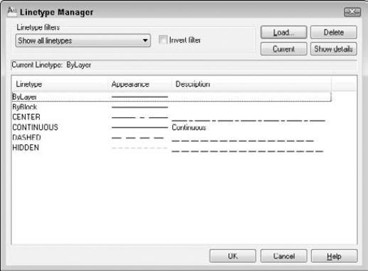
As discussed in the "Assigning a linetype" section earlier in this chapter, you need to load a linetype before you can use it for the first time. To load a linetype, choose Home tab
To filter the list of linetypes, choose from the Linetype Filters drop-down list box in the Linetype Manager.
You can also change the current linetype. When you change the current linetype, all future objects that you draw have that linetype and are not drawn according to their layer's assigned linetype. In general, you should do this only when you have a special need for two objects to be on one layer but have different linetypes. An example might be a table containing notes in one corner of a drawing. You might want the lines that make up the table to have the same layer so that you can freeze it and thaw it (or turn it on and off) easily without having to remember that the table is on two separate layers. If you also want some of the lines to have a different linetype, change the current linetype before adding those lines. Remember to change the current linetype back to ByLayer before drawing anything else.
To change the current linetype, click the Linetype Control drop-down list and choose the linetype that you want, first making sure that no objects are currently selected. You can also use the Properties palette. To change the current linetype back to ByLayer, choose ByLayer for the linetype or use the SETBYLAYER command, discussed earlier in this chapter.
Lineweights let you represent objects with varying line widths. The widths can represent the width of a pen in a pen plotter that will be used to plot that object. Lineweights can also be used as an organizational tool, to distinguish certain types of objects just as colors and linetypes do. Finally, you can use lineweights to represent the actual properties of objects, such as the width of wires in an electrical schematic.
Lineweights work according to the same principles as colors and linetypes. You can control an object's lineweight by using the Lineweight Control drop-down list in the Properties panel of the Home tab. The Lineweight Control drop-down list shows the lineweight of any selected object. When you create a layer, assign it a lineweight, and draw with that layer, the lineweight is displayed as ByLayer.
As with colors and linetypes, the best way to organize a drawing is to assign lineweights by layer. If you need to change the lineweight of an object, do one of the following:
Select the object. Click the Lineweight Control drop-down list and choose the lineweight that you want.
Select the object and open the Properties palette. To change an object's lineweight, click Lineweight, and then click the drop-down arrow that appears. Choose from one of the lineweights.
You can also change the current lineweight. When you change the current lineweight, all future objects that you draw have that lineweight and are not drawn according to their layer's assigned lineweight.
To change the current lineweight, click the Lineweight Control drop-down list and choose the lineweight that you want, first making sure that no objects are currently selected. You can also use the Properties palette. To change the current lineweight back to ByLayer, choose ByLayer as the lineweight or use the SETBYLAYER command, discussed earlier in this chapter.
Note
The drawing used in the following exercise on changing colors, linetypes, and lineweights, ab11-d.dwg, is in the Drawings folder on the DVD.
STEPS: Changing Colors, Linetypes, and Lineweights
Open
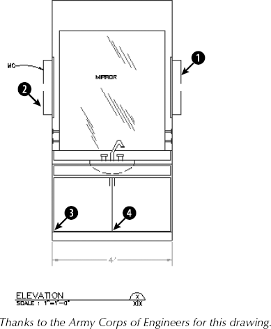
ab11-d.dwgfrom the DVD.Save the file as
ab11-04.dwgin yourAutoCAD Biblefolder. This is an elevation view of a lavatory cabinet, as shown in Figure 11.15.Pick one of the reflection lines in the mirror. Notice that the color is red but the layer's color, as shown in the Layer Control drop-down list, is Magenta. Select all the reflection lines. Choose Home tab
Select the green dimension at the bottom of the cabinet. (The dimension is all one object.) To make it more visible, click the Color Control drop-down list and choose Red. Press Esc to see the result.
Pick the lines at
Select the dashed arc that represents the bottom curvature of the sink. Click the Lineweight Control drop-down list and choose 0.30 mm. Press Esc. Click the Show/Hide Lineweight button on the status bar to turn on the display of lineweights and see the result.
Click the Color Control drop-down list box and choose Cyan to make it the current color.
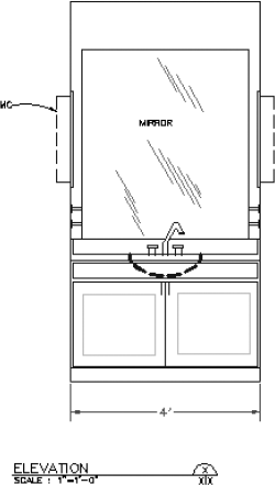
Start the RECTANG command. Draw a rectangle inside the left cabinet. Use the COPY command to copy the rectangle to the right cabinet. To copy, use an intersection object snap at point
Save your drawing. It should look like Figure 11.16.
A noncontinuous linetype is a repeating pattern of dots, dashes, and spaces. Linetypes can also include repeating text or shapes. You may find that the linetype patterns in your drawing are too long or short for clarity. The linetype scale may even be so big or so small that the line looks continuous. How often the pattern is repeated is affected by three factors:
One choice is to change the linetype. A number of linetypes come in short, medium, and long variations, such as Dashedx2, Dashed, and Dashed2, as shown in Figure 11.17.
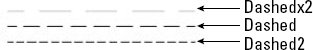
Figure 11.17. A number of the standard linetypes come in three variations, such as Dashedx2, Dashed, and Dashed2.
AutoCAD's acad.lin and AutoCAD LT's acadlt.lin contain a number of ISO linetypes that meet the specifications of the International Standards Organization. Your organization or field of specialty may require the use of these linetypes. The ISO linetype pattern definitions are much longer than the other linetype definitions. You may need to make adjustments to the linetype scale as a result.
Another choice is to change the global linetype scale, which affects all noncontinuous linetypes in your drawing. AutoCAD and AutoCAD LT multiply the linetype definition by the global linetype scale to calculate the length of each repetition of the linetype:
Linetype scales larger than 1 result in longer sections — and fewer repetitions of the linetype definition per unit.
Linetype scales smaller than 1 result in shorter sections — and more repetitions of the linetype definition per unit.
Note
You can also change the scale of a linetype that appears in a viewport on a layout. For more information, see Chapter 17.
When you change the linetype scale, the drawing regenerates to change all the linetypes. Figure 11.18 shows three versions of a drawing with linetypes at linetype scales of 0.5, 1, and 2. As you can see, a scale of 2 is too large and a scale of 0.5 is too small. A scale of 1 is just right. (Goldilocks would have been happy with it.)
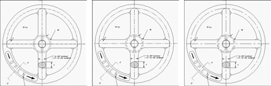
For purposes of drawing, you simply want to make sure that you can distinguish the linetype both when you can see the entire drawing on the screen and when you zoom in close. The main reason to scale linetypes is for plotting. A linetype scale that works for a drawing of a house on-screen may appear continuous when you plot it at a scale factor of 1 = 96.
If you want the linetype to appear exactly according to its definition, use the scale factor for the linetype scale. Chapter 5 covers scale factors. If the scale factor doesn't give you the results that you want, try a linetype scale of one quarter to one half of the scale factor — in the 1 = 96 example, you might use a linetype scale of 24 or 48.
To change the linetype scale, choose Home tab
In the Global Scale Factor text box, type the scale factor that you want. Click OK. The drawing regenerates, changing the scale of every noncontinuous linetype in the drawing.
Tip
The global linetype scale is held in the LTSCALE system variable. You can change the linetype scale by typing ltscale
On occasion, you may want the linetype spacing to be different for one object — or a small group of objects — only. Perhaps the object is too small to show the linetype pattern or you want to set it off visually. The current object linetype scale works like setting a current color or linetype — all objects drawn after you set the object linetype scale are drawn with the new linetype scale. In most cases, you want to make sure that you change the current object linetype scale back to its default of 1 after using it for that one object or group of objects.
To change the linetype scale, Home tab
The current object linetype scale is held in the CELTSCALE system variable. You can also change the current object linetype scale by typing celtscale at the command line and typing in a scale.
If you have also set the global linetype scale to a value other than 1, AutoCAD and AutoCAD LT multiply the two linetype scales to calculate the final result. For example, if you have a global linetype scale of 12 and a current object linetype scale of 0.5, objects you draw will have a resulting linetype scale of 6.
You will often draw an object without setting a special object linetype scale and then decide that you want to change its linetype scale. To change an object's linetype scale, select the object and open the Properties palette. Click Linetype Scale and then type the new linetype scale. This linetype scale affects only the selected object. It does not affect the global linetype scale.
Note
The drawing used in the following exercise on changing linetype scales, ab11-e.dwg, is in the Drawings folder on the DVD.
STEPS: Changing Linetype Scales
Open
ab11-e.dwgfrom the DVD.Save the file as
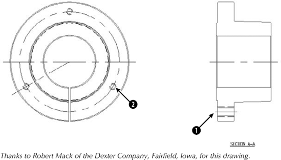
ab11-05.dwgin yourAutoCAD Biblefolder. This drawing is of a bushing, as shown in Figure 11.20. Notice that the linetype doesn't show clearly on the short line atChoose Home tab
Choose the line at
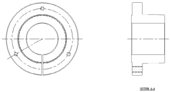
Save your drawing. It should look like Figure 11.21.
Note
Rtltscal gives you real time control over linetype scales. This is a VBA application. Look in SoftwareChapter11
tltscal.dvb.
The DesignCenter gives you access to drawing content and definitions, such as layers, linetypes, blocks (see Chapter 18), plot layouts (see Chapter 17), and so on that exist in other drawings. I cover the DesignCenter in more detail in Chapter 26, but here I explain how to import layers and linetypes from another drawing.
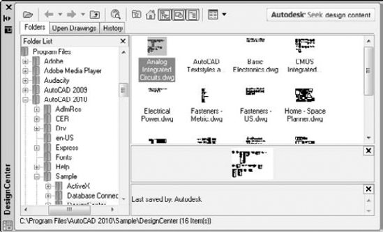
Figure 11.22. The DesignCenter lets you locate definitions that are contained in other drawings and import them into your current drawing.
Note
AutoCAD enables you to translate layers. For example, you can specify that all objects on layer dashed be changed to the layer hidden. Use this feature to maintain layer standards that you have set up. Chapter 26 fully covers layer translating. This feature is not available in AutoCAD LT.
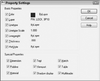
You may be familiar with the Format Painter button available on the toolbars of many Windows applications. AutoCAD and AutoCAD LT offer something similar that at the same time enables you to specify which properties you want to match. AutoCAD calls this process matching properties.
An object can have so many properties that this can be a useful tool. To match properties, you need two objects, a source object and a destination object (or objects). Follow these steps to match properties:

Choose the object whose properties you want to match (the source object).
Note
You can choose the source object first and then start the command.
Then you see the
Select destination object(s) or [Settings]:prompt. If you want to match all the object's properties, select the object(s) that you want to receive the matching properties, that is, the destination object(s).If you want to match only some of the object's properties, right-click and choose Settings to open the Property Settings dialog box, as shown in Figure 11.23. Uncheck all the properties that you don't want to match and click OK. The previous prompt returns. Select the object(s) that you want to receive the matching properties, that is, the destination objects(s).
Press Enter to end object selection and match the properties.
In this chapter, you read all about layers, colors, linetypes, and lineweights. You learned about:
Using layers to help you organize your drawings by assigning the same properties to related objects
Creating a layer by giving it a name, color, linetype, and lineweight in the Layer Properties Manager
Changing the layer of existing objects
Setting layer states — On/Off, Thawed/Frozen, Unlocked/Locked, and Plottable/Not Plottable
Changing the properties of existing layers
Saving sets of layer states and properties and later restoring them
Filtering the layer listing
Purging unused layers and linetypes
Altering the color, linetype, and lineweight of any object
Globally changing the linetype scale, changing the current linetype scale, and changing the object linetype scale of existing objects
Using the DesignCenter to import layers and linetypes from other drawings
Utilizing the Match Properties feature to copy properties from one object to one or more destination objects
The next chapter explains how to get detailed information from your drawing.