
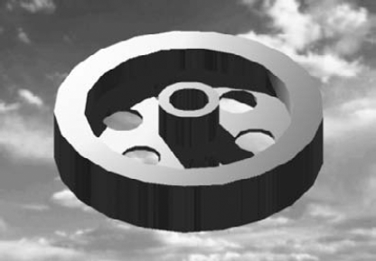
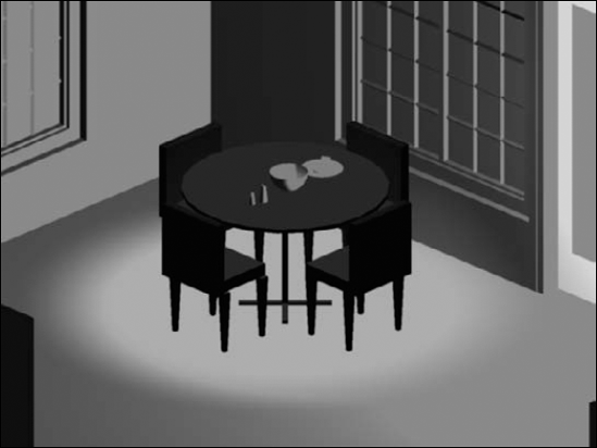
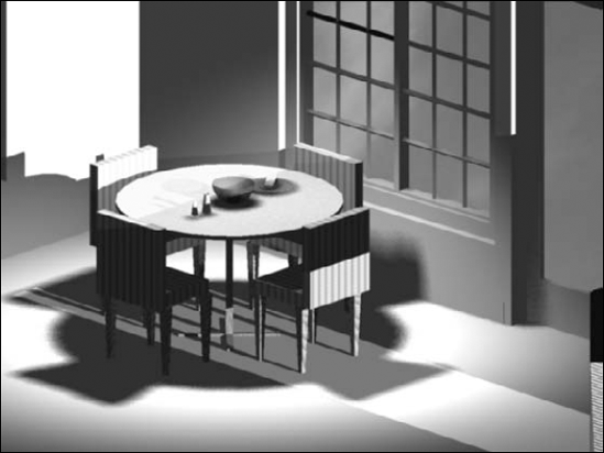
Although 3D drawings are more realistic than those that you create in 2D, they look very artificial — they lack realistic color, shading, and lighting, for example. Rendering enables you to display a 3D drawing more realistically. Some of the more advanced features let you create shadows, make objects transparent, add backgrounds, and map 2D images onto the surface of 3D models. You can shade and render 3D surfaces and solid models. Figure 25.1 shows a whimsical rendering that uses shadows and a background.
Note
AutoCAD LT does not offer any rendering features. This entire chapter applies only to AutoCAD.
This entire chapter assumes that you're in the 3D Modeling workspace. Change the workspace by clicking the Workspace Switching button on the right side of the status bar.
Rendering is a much more sophisticated means of visualizing a drawing than using visual styles is. AutoCAD offers many settings that allow you to fine-tune the results.
Rendering is a multistep process. It generally requires a good deal of trial and error to get the exact results that you want. Here are the steps to render a drawing:
Start with trial rendering by using the default settings. The results let you know what settings need to be changed.
Create lights. AutoCAD has seven types of lights. I explain lights in the "Working with Materials" section later in this chapter.
Create materials. Materials are surface characteristics and include color and/or texture, reflection (shininess), transparency, refraction, and bump maps. These characteristics are explained later in this chapter in the "Working with Materials" section.
Attach materials to the objects in your drawing. You can attach materials by object or layer.
Note
See Chapter 24 for information on how to attach a material to the face of a solid by using the SOLIDEDIT command.
Add a background or fog effect. I discuss these effects in the "Using backgrounds" section later in this chapter.
Fine-tune your rendering preferences, if desired. For example, you can render with a variety of output qualities.
Render the drawing.
The order of the steps is flexible. For example, you can create and attach materials before you add lights. Also, after you render, you'll probably see some room for improvement, so you may go back and make changes.
Tip
Note
The drawing used in the following exercise on creating a default rendering, ab25-a.dwg, is in the Drawings folder on the DVD.
STEPS: Creating a Default Rendering
Open
ab25-a.dwgfrom the DVD.Save the file as
ab25-01.dwgin yourAutoCAD Biblefolder.
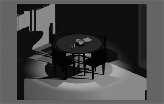
Save your drawing. It should look like Figure 25.2. As you can see, the rendering is too dark and the objects need realistic materials.
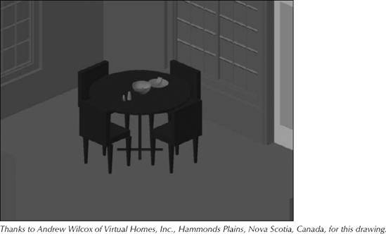
When you render by using the default options, AutoCAD uses default lighting that includes two light sources that fall on the objects in the view. However, the default lighting is rarely enough, nor is it realistic. AutoCAD offers seven types of lights to give you a great deal of flexibility in creating a realistic scene. If you plan to cast shadows in your rendering, the proper placement of lights is most important.
Note
To create lights, choose one of the buttons from the Render tab
Note
AutoCAD offers precise photometry settings for lighting, including the ability to set light intensity using real-world values, such as candela, lumen, or lux. You can also choose the type of lighting (lamp color), such as fluorescent, halogen, or incandescent. To use the photometry feature, you need to set the LIGHTINGUNITS system variable to 1 or 2. A value of 1 enables photometric lighting with American lighting units, and a value of 2 enables it with International lighting units. Set the value of the LIGHTINGUNITS system variable in the Lighting section of the Units dialog box (the UNITS command), or choose Render tab
The default lighting consists of two lights that uniformly light up the model from all directions. You can control brightness and contrast by using the sliders in the Render tab
Tip
Choose Render tab
A point light is equivalent to a typical light bulb or a candle. It comes from a specific location and radiates in all directions. A point light attenuates, meaning that the intensity lessens as the distance away from the light's source increases.
Use object snaps to specify the position of your lights. If there are no objects available, work out the position in advance and place an easily visible point object there; you can then snap to the point object by using the Node object snap. Other options are to type the absolute coordinates or use the From object snap to specify a coordinate, based on an existing geometric point on the model.
If you set the XY coordinates in plan view, be sure to set the proper Z coordinate as well. In an architectural drawing, you rarely want your lights to be coming from the floor! However, in a mechanical drawing, it might be appropriate to light your model from any angle.
Note
If you create an opaque lampshade and place a light inside it, light will get out only through the top and bottom. If you want light to filter through the lampshade, make it partially transparent. For more information, see "Working with Materials" later in this chapter.
The next prompt depends on the value of the LIGHTINGUNITS system variable, as follows:
These options are discussed in the next several sections. After you create the light, you can edit these settings in the Properties palette. When you finish specifying the light's properties, press Enter to exit the command and place the point light.
When you create a light, a default name is automatically created — for example, Pointlight1. Use the Name option to change the name. At the Enter light name <Pointlight1>: prompt, enter a name. You then return to the options prompt. Press Enter to exit the command.
If you change the name, use a name that makes it clear that the light is a point light. Keep the name short; a simple sequence of P1, P2 is often sufficient. However, you could also use P-overhd and P-door or something similar.
Use the Intensity or Intensity factor option to set the intensity, or brightness, of the light. At the Enter intensity (0.00 - max float) <current>: prompt, enter a number. The default is 1; higher numbers make the light brighter. Note that you can also set the brightness by using the Photometry option if you are not using Generic lighting units.
The Status option turns the light on and off. Choose On or Off. You can turn lights on and off to create day and night scenes or to experiment with different lighting arrangements without having to delete or move lights.
If photometry is enabled, use this option to specify the intensity and color of the light. There are two suboptions:
Intensity. You can enter an intensity in candela (abbreviated as cd) units, or you can specify flux, the perceived power of the light, or illuminance, the total flux on a surface area. You can specify illuminance in lux (abbreviated as lx) or footcandle (fc) units.
Color. You can enter a color name or a Kelvin temperature value. Use the
?option and then press Enter to see a list of names, such as Fluorescent, Coolwhite, Halogen, and others. (Press F2 to open the AutoCAD Text window, because the names scroll by too fast to see on the command line.)
Shadows add greatly to the realism of your rendered image. They also add significantly to the rendering time. The Shadow option turns shadows on and off for that light and specifies the type of shadow. If you choose to create shadows, you can choose three types of shadows:
Sharp. These are sometimes called ray-traced shadows. Use these shadows to reduce rendering time.
Soft Mapped. Enter a map size from 64 to 4,096. Larger map sizes are more accurate but take longer to render. At the
Enter softness (1–10) <1>:prompt, enter a number from 1 to 10. The shadow softness determines the number of pixels at the edge of the shadow that are blended into the rest of the image, thus creating the soft effect.Soft Sampled. Creates a penumbra (partial shadow) effect. You can specify values for three suboptions:
Shape. Specify the shape of the shadow and its dimensions. You can choose from Linear, Disk, Rect (rectangle), Sphere, and Cylinder. Then enter a radius at the prompt to specify the size of the shadow.
sAmples. Specify a shadow sample size. The default is 16. A larger sampling size produces a more accurate shadow.
Visibility. You can choose whether or not to make the shape you used for the shadow visible in the drawing. Choose Yes or No (the default). If you choose Yes, you see the shape around the light in the rendering.
Tip
Because shadows add to rendering time, for your practice renderings while you're creating lights and materials, turn shadows off in the Advanced Render Settings palette (RPREF command). Scroll down to the Shadows section and click the Lightbulb icon to toggle shadows on and off. When you're satisfied with the other settings, turn shadows on.
Note
The 3DCONFIG command includes a Hardware Shadows suboption that allows you to turn shadows off. Also, the automatic adaptive degradation may affect shadows if your system is not powerful enough. For more information, see Appendix A.
The Attenuation option sets the attenuation, which is the manner in which the light loses intensity as the distance from its source increases. The Attenuation Type suboption offers three choices:
None. The light doesn't lose intensity.
Inverse Linear. The light loses intensity in a linear manner, so that at 2 units from its source the light is half as intense, and at 4 units away the light is one quarter as intense.
Inverse Squared. The light loses intensity at the square of the distance, so that at 2 units from its source the light is one quarter as intense and at 4 units away the light is one sixteenth as intense. Setting the attenuation to inverse square means that the intensity of the light drops off very quickly.
You can set a limit beyond which there is no light. The reason to do this is to improve rendering time. After a certain distance, it may make no difference if there is a little bit of light or no light, and limiting the light to that difference reduces the required calculations. Set the Use Limits suboption to On if you want to use limits. Then set the Attenuation Start Limit and Attenuation End Limit values. The default start limit is 0 (zero). The end limit is a distance from the center of the light.
Note
The software acceleration driver does not support the use of attenuation start and end limits in the drawing window, but the AutoCAD Device Manager (AcadDM10.hdi) and Direct 3D (direct3d10.hdi) drivers do support attenuation end limits. To find your driver, start the 3DCONFIG command on the command line, and click the View Tune Log button. You should find your driver under the Application Driver item.
You can give your light any color you want. Light colors are somewhat different from pigment colors, which are more familiar. The three primary light colors are red, green, and blue (RGB). Their mixtures are different, as well; for example, red and green make yellow. White light is the sum of all colors of light together. Black is the absence of any colors of light.
Rather than the RGB light color system, you can use the HLS (hue, lightness, saturation) system. Instead of mixing primary colors, you choose the color from a range of hues and then vary its lightness (brightness) and saturation (intensity).
When you use the Color option, you get the Enter true color (R,G,B) or enter an option [Index color/Hsl/colorBook] <255,255,255>: prompt.
To enter RGB numbers, enter numbers from 0 to 255 for red, green, and blue. The default, 255,255,255, is white.
To enter an ACI (AutoCAD Color Index) number, use the Index color suboption and enter a number from 1 to 255. These are the same numbers that you find on the Index Color tab of the Select Color dialog box.
To use the HSL system, use the Hsl option and then enter an HSL color, which is also three numbers from 0 to 255.
To specify a color-book color, use the colorBook option.
Tip
An easier way to assign a light color is to place the light without changing the color, select the light, and change the color in the Properties palette. When you choose Select Color from the Color drop-down list of the Properties palette, the Select Color dialog box opens, where you can see the color swatches for each color. (See Chapter 11 for a discussion of specifying colors and using color books.)
A target point light is like a point light, but you specify a target. This helps you control the direction of the light.
To create a target point light, enter targetpoint on the command line. At the Specify source location <0,0,0>: prompt, enter the source of the light. At the Specify target location <0,0,-10>: prompt, specify the target. By default, the target is 10 units less in the Z direction than the source. The rest of the prompts are the same as for a point light.
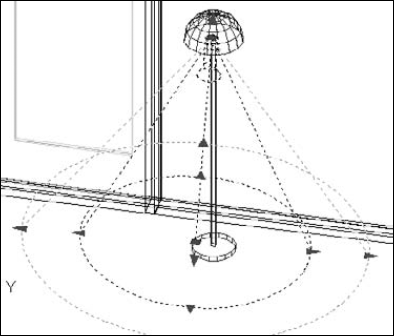
A spotlight differs from a point light in that it has a direction. As a result, you not only specify its location but also its target — two coordinates rather than one. In addition, a spotlight has a brighter center called the hotspot. Outside the center is a ring of lesser brightness called the falloff. Figure 25.3 shows the same scene used previously in this chapter, but with one overhead spotlight.
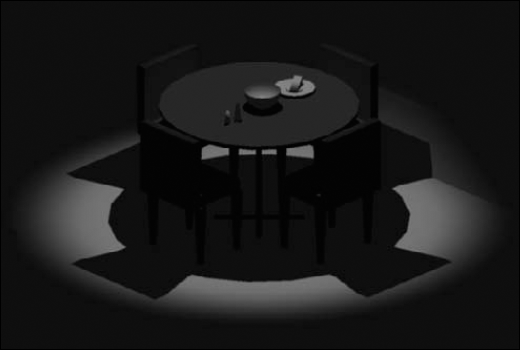
Figure 25.3. A rendering with one spotlight overhead. Here the hotspot angle is 45° and the falloff angle is 70°.
The prompt that you now see depends on the value of the LIGHTINGUNITS system variable (discussed earlier in this chapter), which turns the photometry feature on and off:
If the value is 0, you see the
Enter an option to change [Name/Intensity/Status/Hotspot/Falloff/shadoW/Attenuation/Color/eXit] <eXit>:prompt.If the value is 1 or 2, you see the
Enter an option to change [Name/Intensity factor/Status/Photometry/Hotspot/Falloff/shadoW/Attenuation/filterColor/eXit] <eXit>:prompt.
All these options are the same as for a point light, except the Hotspot and Falloff options. (See the earlier section, "Creating a point light,", for details.)
Set the hotspot and falloff angles for the spotlight. These angles emanate from the spotlight in the direction of the light's target. The maximum angle for both is 160 degrees. If the hotspot and falloff angles are the same, there is no falloff — the entire spotlight is bright. The defaults are 44 degrees for the hotspot and 50 degrees for the falloff. This does not leave very much falloff area. You may need to experiment to get the desired result. When you're done creating the spotlight, press Enter to exit the command.
A free spotlight is like a spotlight, but it has no target. From this perspective, it's like a point light, but it has a hotspot and falloff, like a spotlight.
To create a free spotlight, enter freespot on the command line. At the Specify source location <0,0,0>: prompt, enter the location for the light. The rest of the prompts are the same as for a spotlight.
Using Web lights
Photometric web lights provide a representation of the way a light's intensity varies in 3D space. You would use a web light when you have data about the way a real light's intensity is distributed. The result is a very precise rendering of the effect of the light. However, this result is only approximate in the viewport.
In order to use web lights, you need to turn on the photometry feature by setting the value of the LIGHTINGUNITS system variable to 1 or 2.
You can insert web lights into your drawing by using the following commands:
Weblight: Enter weblight

Freeweb: Enter freeweb
The Web option lets you specify a file that contains light distribution information at various directions from the light in the IES (Illuminating Engineering Society) LM-63-1991 format. IES is a text-file format for describing this type of information. Light manufacturers provide these IES files (sometimes called photometric data) for their lights. You can also specify individual X, Y, and Z data for the light.
After you place a web light, you can select it and use the Web File item in the Properties palette to load an IES file. By default, these web files are in the WebFiles folder. To find the exact location, choose Application Button
A distant light is similar to the sun. Its rays come from so far away that, for all practical purposes, they're parallel. A distant light does not attenuate (unless you're drawing a model on Pluto). Before inserting a distant light, it is recommended that you set the LIGHTINGUNITS system variable to 0 to turn off the photometric units, or lower the distant light's intensity.
You can simulate the sun by specifying a geographic location for your model and setting specific properties for the sun. In this way, you can get very realistic lighting. When you use the sun tools, you are creating a special type of distant light.
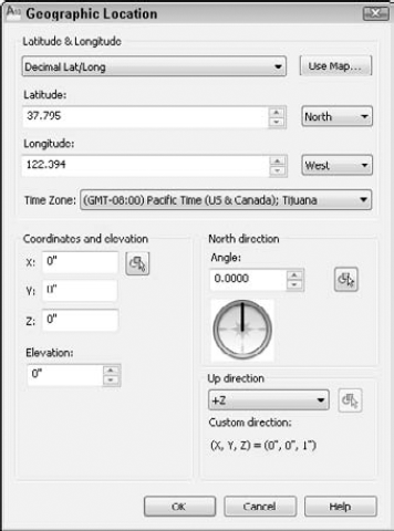
Figure 25.4. Use the Geographic Location dialog box to specify the latitude and longitude for a specific location.
To specify the location, follow these steps in the Geographic Location dialog box:
If you know the latitude and longitude, choose the format, decimal or degrees, in the uppermost drop-down list. Then enter them in the Latitude and Longitude sections, including the hemisphere (North or South and East or West). Then skip to Step 3. Alternatively, click Use Map to display the Location Picker dialog box, and choose the continent from the Region drop-down list. (India and Canada are separately listed among the continents.)
If your model is in a large city, select the Nearest Big City check box. The marker will then jump to the city nearest to the point you click. You can also choose a city from the Nearest City drop-down list. If you're not in a city, just click on the map.
Note
The time zone automatically adjusts to the location you chose. However, you can separately set the time zone by using the Time Zone drop-down list or the TIMEZONE system variable.
In the North Direction section, specify the angle that represents north in your drawing. Setting the north location is important to get accurate sun results. By default, north is the positive Y direction in the World Coordinate System (WCS). To change the default, type a new angle in the Angle box, or click the compass face to specify the new angle. The positive Y axis is at 0 degrees, the positive X axis is at 90 degrees, and so on, clockwise.
Click OK. You may see a notice about the time zone, which is automatically calculated. Check the time zone and click Accept Updated Time Zone to close the notice.
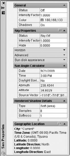
The first set of properties is the same as the options for the POINTLIGHT command. See the section "Creating a point light" earlier in this chapter for more details.
The next four sections only appear if you are using photometric lighting (which means that the LIGHTINGUNITS system variable is 1 or 2).
The Sky Properties section allows you to add a background and illumination effect for the sky when you render the drawing. You don't see any effect in the regular viewport. You can turn the sky off, choose just a sky background effect, or choose both the sky background and the illumination effect. You can add an intensity factor for the sky. The default value is 1. Changing the intensity to 2 will significantly brighten your sky.
Note
To specify these sky properties for a background, turn on photometric lighting and create a new named view. At the bottom of the New View / Shot Properties dialog box, choose the Sun & Sky option. See Chapter 22 for more details on creating a new view with a background.
The Haze setting creates a scattering effect. The default is 0.0 and the maximum is 15.0. A setting of 15.0 will create an effect of looking through haze.
The Horizon section controls the horizon, which is where the ground meets the sky. In order to see the horizon, you need a viewpoint that shows the horizon. If your viewport is too close to plan view, you won't see the horizon, because you'll be looking down instead of outward. You can set the following properties:
Height. Sets the position of the ground plane relative to the zero value of the Z axis. Set this in real-world units. For example, 24 would be 2 feet high.
Blur. Creates a blur at the junction between the ground and the sky. You can see this effect in your drawing (not only when you render), especially if the ground color contrasts with the sky color.
Ground Color. Choose a color for the ground.
The Advanced section includes three "artistic" effects. First, you can choose a night color. You can also turn aerial perspective on. (It's off by default.) Aerial perspective is a bluing and slight blurring effect that creates the impression of distance. Finally, you can set the visibility distance, which is the distance at which 10% haze kicks in, reducing clarity. This setting also gives an impression of distance.
The Sun Disk Appearance section affects only the appearance of the sun, not the overall light. You can see the results of the changes you make here more clearly in the New View / Shot Properties dialog box. The Disk Scale item specifies a scale for the sun disk itself; a value of 1 is normal size. The Glow Intensity item changes the glow around the disk; 1 is the default value. The Disk Intensity value changes the intensity of the sun disk itself; again 1 is the default value.
The Sun Angle Calculator section allows you to enter a date and time and to specify whether or not you're using Daylight Savings Time. To change the date, click the Date item, and then click the Ellipsis button. A little calendar opens. Navigate to the desired date and double-click it. The calendar closes. Choose a time from the drop-down list. Choose Yes or No from the Daylight Saving drop-down list.
The next three settings are not changeable; they're based on the location you specified in the Geographic Location dialog box (or the values you previously choose for Date, Time, and Daylight Savings):
The azimuth is the angle in the XY plane — North is located at 0 degrees. Use a positive angle to move clockwise from North, and a negative angle to move counterclockwise from North. Values can range from −180 to 180. (Both −180 and 180 would represent South.)
The altitude is the angle from the XY plane. You can type in angles from −90 to 90. (An altitude of −90 would mean that the light was coming from beneath the model.)
The source vector is the coordinates that represent the sun's direction. For more information on the vector system, see "Using the VPOINT command" in Chapter 22.
The Rendered Shadow Details section offers the same settings I discussed earlier in the "Creating a point light" section. However, when photometric lighting is on, the only shadow choice is Soft (Area), which creates sampled shadows. Shadows need to be on in the General section for these settings to be available.
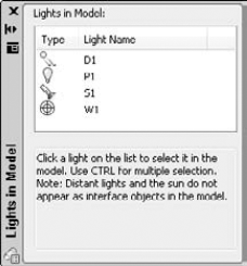
Lights can be difficult to select; they may be inside a lamp or high up, out of your current display. Distant lights don't have a glyph that you can click on to select them. The Lights in Model palette helps you select, modify, and delete lights. To select a light, choose it in the palette.
You can now edit the light either with grips or in the Properties palette. Figure 25.7 shows a selected spotlight. You can easily change the spotlight's location, target, hotspot, and falloff by using grips. To change its status (on or off), color, and other properties, use the Properties palette.
To delete a light, choose it in the Lights in Model palette and press Del. You don't delete the sun, you just turn it off. (Good night!)
Note
You may have lights that you created in AutoCAD versions prior to 2007 that you want to use in 2010 drawings. Use the CONVERTOLDLIGHTS command to convert your lights. You may have to adjust their intensity. To do so, select them and change the intensity in the Properties palette. In addition, the 3DCONVERSIONMODE system variable converts material and light definitions to the latest release. This system variable allows you to keep your definitions up-to-date with each new release.
Note
The drawing used in the following exercise on creating lights and shadows, ab25-a.dwg, is in the Drawings folder on the DVD.
STEPS: Creating Lights and Shadows
Open
ab25-a.dwgfrom the DVD. Object Snap should be on. Set running object snaps for Endpoint and Center. This exercise does not use the photometric feature; make sure that the value of the LIGHTINGUNITS system variable is set to 0.Save the file as
ab25-02.dwgin yourAutoCAD Biblefolder.
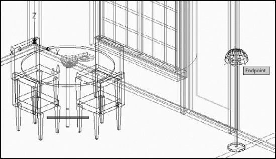
Pan to the right until you see the floor lamp, as shown in Figure 25.8.
Follow the prompts: Specify source location <0,0,0>:
Pick the endpoint shown in Figure 25.8. Enter an option to change [Name/Intensity/Status/shadoW/Attenuation/Color/eXit] <eXit>:nEnter light name <Pointlight1>:p1Enter an option to change [Name/Intensity/Status/shadoW/Attenuation/Color/eXit] <eXit>:iEnter intensity (0.00 - max float) <1.0000>:3Enter an option to change [Name/Intensity/Status/shadoW/Attenuation/Color/eXit] <eXit>:xChoose Render tab

Open the Properties palette (Ctrl+1). Click the Filter Color item and choose Yellow from the drop-down list. Click the Shadows item and choose On from the drop-down list (if it's not already on).
Choose Views tab

Specify source location <0,0,0>: _
Shift+right-click and choose From from the OSNAP list. from Base point:Use the Center object snap of the top edge of the round table. <Offset>:@0,0,5'(This places the light 5 feet directly over the table, like a light hanging from the ceiling.)Specify target location <0,0,−10>:Use the Center object snap of the top of the table.Point to the edge of the round table. Enter an option to change [Name/Intensity/Status/Hotspot/Falloff/shadoW/Attenuation/Color/eXit] <eXit>:nEnter light name <Spotlight1>:s1Enter an option to change [Name/Intensity/Status/Hotspot/Falloff/shadoW/Attenuation/Color/eXit] <eXit>:fEnter falloff angle (0.00-160.00) <50>:70Enter an option to change [Name/Intensity/Status/Hotspot/Falloff/shadoW/Attenuation/Color/eXit] <eXit>:hEnter hotspot angle (0.00-160.00) <3'-9">:40Enter an option to change [Name/Intensity/Status/Hotspot/Falloff/shadoW/Attenuation/Color/eXit] <eXit>:wEnter shadow settings [Off/Sharp/soFtmapped/softsAmpled] <Sharp>:fEnter map size [64/128/256/512/1024/2048/4096] <256>:Enter softness (1-10) <1>:5Enter an option to change [Name/Intensity/Status/Hotspot/Falloff/shadoW/Attenuation/Color/eXit] <eXit>:x
Choose Render tab
Close the Sun Properties and Lights in Model palettes (or auto-hide them).
Choose Render tab

Display the Advanced Render Settings palette again. Click the Specifies If Shadows Are Computed lightbulb icon in the Shadows section. Click Render. Notice that the rendering takes much longer. Lots of shadows this time! This rendering also makes it clear that no light is coming through the windows. (See the "Working with Materials" section to learn how to make materials transparent.) The rendering should look like Figure 25.10.
Save your drawing. If you're continuing on to the next exercise, keep this drawing open.
Materials in AutoCAD are representations of actual materials on objects, such as glass, metal, fabric, wood, and others. Using materials is an important part of the rendering process and greatly affects the results. Materials interact with lights. For example, shiny materials reflect light differently than dull materials because shiny materials create highlights.
Note
The Adaptive Degradation process may turn off materials automatically if your graphics card is not certified. You can turn the display of materials on manually by using the 3DCONFIG command. For more information, see Appendix A.
The easiest way to attach a material to an object is to use the collection of materials on the Tool Palettes window. To get an idea of the available materials, open the Tool Palettes window (Ctrl+3) and click the overlapping tabs at the bottom of the window to display the full list of tabs. Notice that there are tabs that contain material samples and others that contain a materials library.
Tip
Right-click the Tool Palettes window's title bar and choose Materials to display the tool palettes related to materials.
To apply a material to an object, choose a palette (tab) and click a material swatch on the tool palette. At the Select objects: prompt, select the objects for the material. You should see the change immediately if you have materials and textures set to display.
Note
The drawing used in the following exercise on attaching materials from the Tool Palettes window, ab25-02.dwg, is in the Results folder on the DVD.
STEPS: Attaching Materials from the Tool Palettes Window
If you have
ab25-02.dwgopen, use this file. Otherwise, open it from yourAutoCAD Biblefolder or theResultsfolder on the DVD.Save the file as
ab25-03.dwgin yourAutoCAD Biblefolder.
Choose Render tab
Display the Tool Palettes window (Ctrl+3). Click the overlapping tabs at the bottom and choose Woods and Plastics - Materials Sample.
Click the
Woods - Plastics.Finish Carpentry.Wood.Mapletool. (If you get a dialog box saying that the material exists, choose to overwrite it.) At theSelect objects:prompt, select the tabletop. The tabletop changes color, but still doesn't look very much like wood. In the next exercise, you'll fix that. Press Enter to end object selection.
Tip
You can also access the properties of a material by right-clicking the material in the Tool Palettes window and choosing Properties to open a dialog box for that material.
The top section of the Materials palette displays all the materials currently in the drawing. You can use the Toggle Display Mode button to switch between showing one material and rows of materials. You can select any material to see and change its properties.
You can right-click any material in the preview area and do the following from the shortcut menu:
Create a new material.
Apply the material to selected objects.
Select objects that use the material.
Edit the material's name and description.
Purge the material if it's not in use.
Export the material to the active tool palette so that you can attach the material from there.
Copy the material (so that you can create a new material based on the old one).
Change the size of the material swatches. If you have a lot of materials, use the small size.
To edit an existing material, select the material and adjust its properties. I explain the properties in the next section. When you have the materials you need, you attach them to objects. See the section "Attaching materials" for details.
To create your own material, click the Create New Material button in the Materials palette. In the Create New Material dialog box, enter a name and description for the material and click OK. A new swatch appears in the Materials palette. You can now specify the properties for that material.
Note that you can also modify an existing material or copy an existing material and modify that copy. In fact, to get the results that you want, you often need to modify an existing material in some way. To copy a material, select it, right-click, and choose Copy. Then right-click and choose Paste.
The first step is to choose a material type. A material type provides you with the basic properties that are common to that class of materials. Choose the type you want from the Type drop-down list. AutoCAD has the following basic material types:
Realistic. The main type for most materials. It has moderate shininess, and zero refraction, translucency, and self-illumination. I explain these terms in the next section.
Realistic Metal. The main type for metals. It has moderate shininess and no self-illumination. Translucency and refraction are not available.
Advanced. Like realistic, but offers the ability to separately specify ambient, diffuse, and specular colors. I explain these terms in the next section.
Advanced Metal. Like Realistic Metal, but offers the ability to separately specify ambient and diffuse colors.
In addition, there are over 15 templates that are more specific (wood, water, and so on) and that assist you in creating your own materials by providing many settings for you. Choose these from the Template drop-down list, or choose User-Defined to specify properties from scratch. The type that you choose from the Type drop-down list determines the available templates.
Note
You can force materials to be two-sided. This option is available in the Advanced Render Settings palette, which I cover later in this chapter. By default, this setting is on. If you turn it off, when you create a material, you can check or uncheck the Two Sided Material check box in the Materials palette. One-sided materials take less time to render.
The next step is to specify the properties for your new material. The section of the Materials palette just below the Type drop-down list varies, depending on the type you chose. Figure 25.12 shows the section for the Advanced type. This section offers one, two, or three kinds of colors that you can apply to the material.
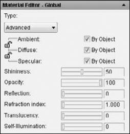
The first set of properties includes basic colors that apply to the material. These colors are as follows:
Ambient. This is the color that appears on objects lighted by ambient light alone. Ambient light is turned off when you turn on lights that you create for the drawing; when you turn off all lights (or if you don't add any), the ambient light applies. This property is available for the Advanced and Advanced Metal types.
Diffuse. This is the main color of the object. All material types allow you to set the diffuse color. Note that colored lights have a significant effect on the apparent color of a material.
Specular. This is the color of a highlight on a shiny material. For example, a shiny metal may have a white highlight. The higher the shininess of the material, the bigger the highlight gets. Only the Advanced template has the specular property.
For all three settings, you can specify a color or use the object's color. The object's color is usually the color of the object's layer. Clear the By Object check box to assign a different color to the property. Then click the gray box next to that property to open the Select Color dialog box where you can choose a color.
When you use either the Advanced or Advanced Metal type, you can lock the Ambient color to the Diffuse color by clicking the lock between the two. The Advanced type also lets you lock the Specular color to the Diffuse color.
The next set of properties includes the overall properties that affect how the material looks and reflects light. When you create materials, try varying these settings until you get the results you want. These properties vary according to the material type, so you may not see some of these options. They are the following:
Shininess. This affects the highlight on an object. Higher shininess creates a brighter, but smaller, highlight. Lower shininess creates a larger, softer highlight.
Opacity. Sets the opacity (or transparency) of the object. Zero opacity creates a transparent material.
Reflection. Specifies the reflectivity of the material. A material with a reflection of 100 is like a mirror.
Refraction Index. Refraction specifies how light bends when it passes through a translucent material, creating a distorted effect. Glass refracts very little, but a crystal ball refracts quite a bit. If you don't want any refraction, use a 1.0 setting, the refraction of air.
Translucency. This is the amount of light that passes through an object. The value is a percentage. A value of 0.0 means that the object is opaque. A value of 100.0 means that the object is as transparent as possible.
Self-illumination. This makes the object appear to have its own light, regardless of the lights that you add. You could represent a glowing log in a fireplace in this way.
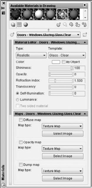
The bottom section of the Materials palette allows you to add three types of 2D image files that map an image onto a 3D model to add interest to your materials. You choose these from the drop-down lists:
Diffuse map. There are nine kinds of diffuse maps. Texture maps allow you to add any type of pattern to a plain color. For example, you can add a bitmap image of a plaid to a fabric material. The other seven types of maps are procedural maps, which allow you to specify a variety of settings to define the map. Procedural maps use mathematical algorithmsinstead of bitmaps to define a material, thus giving you many more options. You can choose from Checker, Gradient Ramp, Marble, Noise, Speckle, Tiles, Waves, and Wood.
Reflection map. This is available if you choose the Advanced or Advanced Metal material type. You have the same options as for diffuse maps. Reflection maps simulate outside objects reflected on the surface of a shiny object, such as a room seen on a shiny doorknob.
Opacity map. Mimics areas of opacity and transparency when a material needs to vary in opacity. Anywhere that the opacity map is applied is transparent, while other areas are opaque. You can choose from the same types listed for diffuse maps.
Bump map. Creates the effect of varying heights, that is, bumps. An image used for a bump map is usually black and white, and meshes with a texture map to simulate changes in height. You have the same types as for diffuse maps.
For each type, choose the Click for [map type] Settings button, shown in Figure 25.13, to display the settings dialog box for the selected map type. Then choose the button that is to the right of the Current Material tree, just below the material swatches, labeled Up One Level to Parent Map, to return to the top level of the current material. There, you can use the slider to specify the percent of the map that shows. If you drag the slider to the left, you see no effect; drag the slider to the right for the full effect. Click the Select button to choose the image that you want to map onto the material.
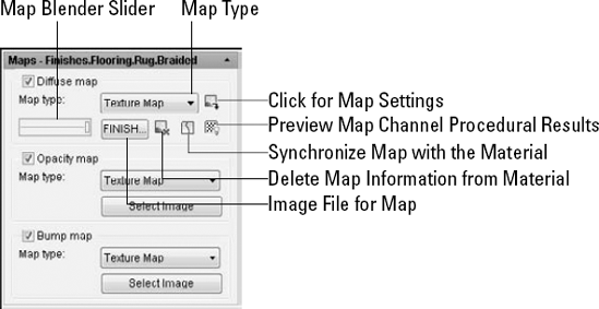
Click the Delete Map Information from Material button to delete the image and clear any settings made for the selected map type.
You can use JPEG, BMP, RLE, DIB, TIF, GIF, PNG, TGA, or PCX image files for textures maps. AutoCAD comes with a large selection of map files. To find them, choose Application Button
Tip
You can use your own photographs for texture maps. For example, you could take a photo of some wood, stone, or pebbles and use it to create a material.
You can adjust these effects in the Material Scaling & Tiling and the Material Offset & Preview sections of the Materials palette, as shown in Figure 25.14.
If you choose a texture map, the Material Scaling & Tiling section appears, where you can scale and tile the image. You can choose a unit from the Scale Units drop-down list to scale in real units or leave it unitless. If you choose a unit, you can set the width and height to Tile, Mirror, or None (no tiling or mirroring). Then enter values in the Width and Height text boxes. Click the lock to make sure that the scaling is the same in both directions. Select Fit to Gizmo from the Scale Units drop-down list to avoid scaling the pattern and instead fit it to the object. (Fitting to an object is always unitless.)
Note
U and V are directions, like X and Y, but they follow the image. For example, if you rotate the object that contains the material, the U and V directions follow along; they are not tied to the User Coordinate System.
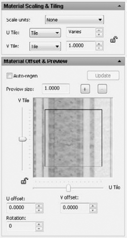
Figure 25.14. You can adjust the scale, tiling, offset, and rotation of any map that you use for a material.
In the Material Offset & Preview section, you can change the offset of the pattern (move it) by dragging the preview directly or using the U Offset and V Offset text boxes or arrows. Finally, you can rotate the pattern by using the Rotation text box or arrows. You can also right-click in the preview area and drag to rotate the pattern.
The way in which a material, especially one with a texture, maps onto an object may not be suitable for that object's shape. For example, mapping a floral pattern onto a flat surface is different from mapping it onto the wall of a cylindrical shape. If the pattern has a direction, you may want to rotate it.
Use the MATERIALMAP command to fine-tune the mapping of a material. Choose Render tab
Note
You may have materials that you created in AutoCAD 2007 and previous releases that you would like to use. You must convert such materials to work with AutoCAD 2010. Use the CONVERTOLDMATERIALS command for this purpose. You may need to adjust the mapping for the materials by using the Material Scaling & Tiling and the Material Offset & Preview sections of the Materials palette, as described in the previous section. In addition, the 3DCONVERSIONMODE system variable can convert material and light definitions to the latest release. This system variable allows you to keep your definitions up-to-date with each new release.
The Advanced Lighting Override section of the Materials palette lets you change properties of a material for Realistic and Realistic Metal material types. (For other types, this section doesn't display.) These properties specify the effects of reflected and indirect light. You can set the following properties:
Color Bleed Scale. Color bleeding is the effect of light on nearby surfaces. For example, a blue carpet may make the white wall appear blue. Drag the slider to increase or decrease color bleeding.
Indirect Bump Scale. If you added a bump map, you can use this slider to adjust the effect in areas lit by indirect light.
Reflectance Scale. Reflectance is the amount of diffuse light that a material reflects. Use the slider to adjust the value.
Transmittance Scale. Transmittance is the amount of light transmitted through a material and is related to transparency. An opaque material has 0% transmittance. Use the slider to adjust this value.
Note
The drawing used in the following exercise on modifying and creating materials, ab25-03.dwg, is in the Results folder on the DVD.
STEPS: Modifying and Creating Materials
If you have
ab25-03.dwgopen from the previous exercise, use this file. Otherwise, open it from yourAutoCAD Biblefolder (if you did the exercise) or theResultsfolder of the DVD.Save the file as
ab25-04.dwgin yourAutoCAD Biblefolder.If you can't see the beige color on the table top, choose Render tab
Choose Render tab

To create a material for the wedge of cheese on the plate, in the Materials palette, click Create New Material. In the Create New Material dialog box, name the material Yellow Cheese. For the description, enter yellow plastic plus bumps. Click OK. A new preview swatch appears for Yellow Cheese. From the Swatch Geometry drop-down list, choose the cube.
Use the following settings for Yellow Cheese:
Type. Realistic.
Template. User-Defined.
Diffuse. If the By Object check box is checked, uncheck it. Click the color swatch. From the Index Color tab of the Select Color dialog box, choose Index Color 51, a light yellow. Click OK.
Shininess. Drag the Shininess slider down to about 20. Cheese isn't very shiny.
Bump Map. In the Maps section, click the Select Image button below the Bump Map check box. From the
TexturesBumpfolder, chooseFinishes.Painting.Paint.bump.jpg. Click Open. Then drag the bump map slider all the way to the right.Note
If the Select Image File dialog box doesn't open to the right folder, you may need to navigate to it. To check the location of the folder, close the dialog box and choose Application Button
Click the expand arrow of the Material Scaling & Tiling section. Set the Scale Units to Inches, and the height and width to 0.5. The Width and Height drop-down lists should be set to Tile.
Right-click the Yellow Cheese material swatch and choose Apply Material. At the
Select objects:prompt, select the wedge on the plate to attach the Yellow Cheese material. Press Enter to end object selection.Note
You may not be able to see the bump map in your drawing. To see it, choose Render tab
Save your drawing.
After you import, create, and modify the materials that you need, you can attach them to objects. AutoCAD lets you attach materials by object or layer. In fact, these two options allow you to attach a material to the following:
An entire object by selecting the object
Any objects on a specified layer, including layers of objects within a block
A face on an object (by subselecting the face)
I've already discussed how to attach materials from the Tool Palettes window in the "Attaching a material from the Tool Palettes window" section earlier in this chapter. To attach any material to an object from the Materials palette, follow these steps:
Choose Render tab
Choose the material from the swatches.
Click the Apply Material to Objects button.
At the
Select objects:prompt, select the objects. You can use subselection (press Ctrl) to select a face of a solid.
Tip
An easy way to attach a material is to select an object and choose the material you want from the Material property in the Properties palette.
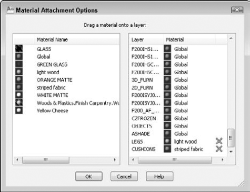
Figure 25.15. Use the Material Attachment Options dialog box to attach a material to all objects on a layer.
Drag any material on the left to a layer on the right to attach the material. To detach a material from a layer, click the Detach button (the X) that appears in the right-hand column.
Tip
Attaching materials by layer can be a very efficient method, but it requires some planning in advance. For example, if you have a block that is a chair, you can create it so that the legs are on one layer and the seat and back are on a different layer; then you can easily attach a wood-like material to the legs and a decorative pattern to the seat and back.
You can add a background to a rendering by saving a view that includes a background. In Chapter 22, I explain how to add a background by using the VIEW command. For example, you can place a picture of the sky in the background (see Figure 25.1 in this chapter).
Note
Releases of AutoCAD prior to 2007 included a scenes feature that allowed you to save views and light settings. Scenes are no longer available. The same is true of landscape objects, which included trees and other objects.
Note
The files used in the following exercise on attaching materials and adding a background, ab25-b.dwg and bluesky.jpg, are in the Drawings folder on the DVD.
STEPS: Attaching Materials and Adding a Background
Open
ab25-b.dwgfrom the DVD. Use Windows Explorer to copybluesky.jpgfrom theDrawingsfolder of the DVD to yourAutoCAD Biblefolder.Save the file as
ab25-05.dwgin yourAutoCAD Biblefolder. This is the same drawing used earlier in the chapter, but all the materials have been imported and modified, and some materials have been attached to objects. Also, the table and chairs have been separated into appropriate layers.If you're not in the Realistic visual style, choose Render tab

In the Materials palette, choose
GREEN GLASSand click the Apply Material to Objects button. At theSelect objects:prompt, select the plate on the table and press Enter to end selection.Choose Home tab
Click the Browse button. In the Select File dialog box, you may need to change the Files of Type drop-down list to All Image Files. Select
bluesky.jpg(which you copied to yourAutoCAD Biblefolder in Step 1) and click Open.In the Background dialog box, click Adjust Image. From the Image Position drop-down list, choose Stretch. You can see how the image improves. Click OK three times to return to the View Manager. Click Set Current and click OK to return to your drawing. You should see the image appear through the windows. (If not, you may need to render the drawing.)
Save your drawing. Keep it open if you're continuing to the next exercise.
You're finally ready for your final rendering. Preparing to render can be a long process. At this time, you may want to look at some of the more specialized settings for rendering in the Advanced Render Settings palette, as shown in Figure 25.16. To open the Advanced Render Settings palette (the RPREF command), choose Render tab
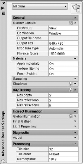
Figure 25.16. The Advanced Render Settings palette lets you set many rendering options. This figure shows about half of the available settings.
At the top of the Advanced Render Settings palette is the drop-down list of the render presets. Render presets are groups of settings that you can use when you don't want to customize the settings. You can choose from Draft, Low, Medium (the default), High, and Presentation. (You can customize the presets themselves, by choosing Render tab
The Render Context section contains settings that relate to the rendering as a whole. This section allows you to choose how your model gets rendered. Here are your options:
Save File. Click the Determines If File Is Written button if you want to save the resulting rendering to a file. Click the same button to cancel saving to a file.
Procedure. You can render the current view, crop to a window, or render selected objects.
Destination. You can render to the current viewport or to a separate window.
Output File Name. If you chose to save a file, click this item, then click the Ellipsis button to navigate to a location, and enter a filename. You can save renderings as BMP, TIF, JPEG, PNG, TGA, or PCX files.
Output Size. Choose an output size (in pixels) from the drop-down list or choose Specify Output Size to customize your size settings.
Exposure Type. Choose Automatic or Logarithmic. Automatic exposure is the default output setting, and is the setting used with releases prior to AutoCAD 2009. The Logarithmic setting is useful when you want more control over exposure, but are not using photometric lighting.
Physical Scale. This setting helps to reduce artifacts (imperfections) caused by changes in exposure. The default value is 1500. If you see artifacts, you need to experiment to find a value that works for you; the best value in a drawing with a sun will be different than in a drawing with just point lights.
The Materials section has settings relating to materials. You can specify the following:
Apply Materials. Turns materials on and off.
Texture Filtering. Samples textures by area to avoid aliasing, which results in artifacts, such as a jagged or moiré effect.
Force 2-Sided. Renders both sides of faces, even those facing away from the view. You can turn this off to speed up rendering.
The Sampling section offers settings to control sampling, which is the precision with which the rendering deals with each pixel. A lower minimum sampling rate is quicker but less accurate. A 1/4 sampling rate (the default) makes one calculation for every four pixels. The maximum sampling rate applies when the neighboring pixels are different enough (have enough contrast) to require more precise sampling. The default is 1, which is one calculation per pixel. The contrast colors control the contrast values used to determine how much sampling to do, based on the minimum and maximum rates.
The Shadows section has a Lightbulb button that turns shadows on and off. You can turn shadows off to speed up rendering. The Mode determines the order in which shadows are computed — Simple (randomly), Sorted (from an object to the light), and Segment (along the light ray). Shadow Map turns on shadow mapping. When this is off, shadows are ray-traced, which results in sharper and more accurate outlines. Shadow maps allow for soft shadows.
The Sampling Multiplier limits sampling for shadows throughout the drawing. Use this feature to create draft renders. Lower values mean less sampling; higher values produce more accurate results. Values range from 0 to 2.
The Ray Tracing section affects how the renderer calculates ray-traced shadows. The Lightbulb button turns ray tracing on and off. The Max Depth setting controls how many reflections and refractions can be calculated. You can also individually set the maximum reflections and refractions that are calculated.
The Indirect Illumination section has three subsections — all relate to subtle light effects in addition to direct lights that you create. These settings control radiosity, the simulation of multiple reflections of light as they interact with each other, to create more natural lighting. For example, Global Illumination creates color bleeding, which occurs when the color of one surface affects the color of a nearby surface. Final Gather adds an additional calculation to eliminate dark corners and other artifacts, but adds greatly to rendering time. The Light Properties section has controls that affect lights that you create when you use indirect illumination. You can increase the accuracy and brightness of lights with these settings, but doing so increases rendering time.
The Diagnostic section helps troubleshoot the rendering results. You can turn on the display of a grid to help understand how the renderer is placing an object. You may have noticed that when you render, the rendering appears tile by tile. You can change the size of this tile, the order of the tiling, and the maximum memory used during the rendering process.
To render, choose Render tab
Note
The drawing used in the following exercise on creating a final rendering, ab25-05.dwg, is in the Results folder on the DVD.
STEPS: Creating a Final Rendering
If you have
ab25-05.dwgopen, use this file. Otherwise, open it from yourAutoCAD Biblefolder if you did the previous exercise, or from theResultsfolder of the DVD.Save the file as
ab25-06.dwgin yourAutoCAD Biblefolder.Choose Render tab
Choose Render tab
Choose Render tab
The Rendering window should open. Wait until AutoCAD finishes the rendering. Look at those shadows! Can you see the orange in the transparent green bowl? Note the sky image outside the window.
The rendering should look like Figure 25.17, only a lot better because you see it in color on your screen. Save your drawing.
Remember that rendering is a trial-and-error process. Don't expect to get it right the first time. You can probably see several areas that require improvement. At this point, you would go back and tweak the lights, materials, and so on until you were satisfied.
Note
AccuRender is a rendering program that offers additional rendering capabilities. Look for it in SoftwareChapter 25.
When you render to the render window, the right pane lists a number of statistics relating to your rendering. You can use these statistics to troubleshoot or compare results among renderings. The bottom pane shows your rendering history.
You can save your rendered images and re-display them at another time. You can also use saved rendered images in other applications and print them from those applications. Here are the steps to saving a rendering to an image file:
Render the image.
After rendering to a viewport, on the command line, type saveimg
After rendering to the render window, choose File
In the Render Output File dialog box, choose a file type, enter a filename, and click Save. In the Render Output File dialog box, choose a file type from the File of Type drop-down list. Choose a location and enter a name for the file.
Depending on the image type that you choose, you'll see a dialog box offering options such as the number of colors and the quality. Choose the options you want and click OK to save the image.
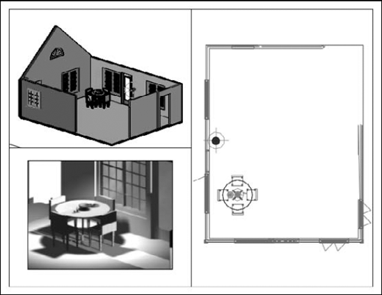
You can import these saved rendered images back into your drawing. Figure 25.18 shows three floating viewports. One of the views shows the rendered image.
Note
See Chapter 27 for detailed instructions on importing images. You can plot rendered viewports, as I explain in Chapter 17.
In this chapter, I covered the process of rendering. You read about the following:
Creating lights
Importing and creating materials
Attaching materials
Using backgrounds
Rendering a drawing
This chapter ends Part IV, "Drawing in Three Dimensions." Part V, "Organizing and Managing Drawings," explains how to manage drawings, work with other applications and file types, and use AutoCAD on the Internet.