
Although you can create great-looking models with surfaces, if you want truly realistic models, you need to create solids. After all, in real life, objects have solidity. Even a thin object such as a wastepaper basket or a drape has some thickness. Solids enable you to create more realistic models than surfaces. You can also combine or subtract solids and get information about their physical properties.
Note
AutoCAD LT doesn't draw solids. For the 3D capabilities of AutoCAD LT, see Chapters 21 and 22.
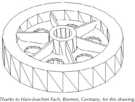
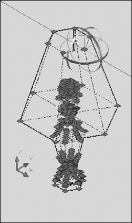
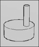
Figure 24.1 shows a complex model created using solids.
As I explain in Chapter 21, when working in 3D, you should use a 3D environment. This includes the following items:
The 3D Modeling workspace, which you choose from the Workspace Switching button on the status bar. (I explain how to customize workspaces in Appendix A.)
The
acad3d.dwttemplate (oracadiso3d.dwtor similar template) that turns on perspective view, the grid, and the Realistic or other 3D visual style. (I cover visual styles in Chapter 22.)The ribbon, which combines many modeling commands and settings in one place.
To work with solids, you can use the Modeling panel on the Home tab of the ribbon. This entire chapter assumes that you're using the 3D Modeling workspace.
As with surfaces, AutoCAD makes it easy to create most basic geometrical shapes. These shapes are easy to draw, because you can dynamically see the result as you draw.
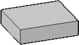
The box is one of the most commonly used 3D objects and is often the basis for more complex models. Figure 24.2 shows a solid box shown with the 3D Hidden visual style. Visually, it looks the same as a surface box.
To draw a box, follow these steps:

At the
Specify first corner or [Center]:prompt, specify any corner of the box, or right-click and choose Center to specify the 3D center of the box (not the center of the base).If you specify the corner (the default), you then see the
Specify other corner or [Cube/Length]:prompt.The default is to pick the opposite corner in the XY plane. This defines the base of the box. You can define the base just like you define any rectangle, by dragging and picking the opposite corner or by entering coordinates. At the
Specify height or [2Point]:prompt, drag in the Z direction and pick a height or enter a height value. You can also pick two points to specify the height. This completes the box.If you use the Length option, AutoCAD asks you for a width and a height. If you use the Cube option, AutoCAD asks for one length and completes the box.
If you specify the center at the first prompt, you see the
Specify center:prompt. Specify the center of the box. TheSpecify corner or [Cube/Length]:prompt appears.If you pick the corner of the box, AutoCAD then asks you for the height to complete the box.
If you specify the length, AutoCAD then asks for a width and a height. If you use the Cube option, AutoCAD asks for a length and completes the box.
You can specify a negative length, width, or height to build the box in the negative direction. If you specify the center of the cube, don't forget that the center's Z coordinate is different from the corner's Z coordinate. AutoCAD always creates the box parallel to the XY plane.
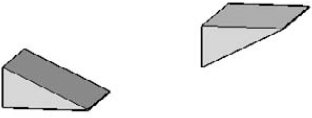
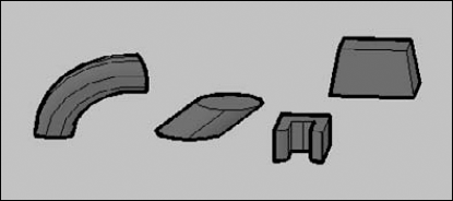
A wedge is a box sliced diagonally in half. The prompts are virtually the same as for the Box command. Figure 24.3 shows two wedges.
To create a wedge, follow these steps:

At the
Specify first corner or [Center]:prompt, specify any corner of the wedge or use the Center option to specify the 3D center of the wedge.If you specify the corner (the default), you then see the
Specify other corner or [Cube/Length]: prompt.The default is to pick the opposite corner in the XY plane — you can also define itby using coordinates. The command then asks you for the height in the Z direction. This completes the wedge.
If you use the Length option, AutoCAD asks you for a width and a height.
If you use the Cube option, AutoCAD asks for one length and completes the wedge. For positive lengths, the wedge slopes downward in the positive X direction. (However, if you have Dynamic Input on, the slope will follow the direction of the cursor.)
If you specify the center, you see the
Specify center:prompt. Specify the center point. TheSpecify corner or [Cube/Length]:prompt displays.If you pick the corner of the wedge, the command asks for a height.
If you specify the length, AutoCAD then asks for a width and a height. If you use the Cube option, AutoCAD asks for a length and completes the wedge.
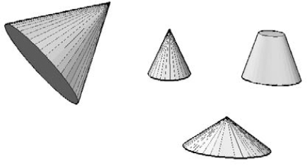
You can draw cones with circular or elliptical bases. By specifying a negative height, you can create an inverted cone (like an ice-cream cone). By specifying the Axis endpoint (the apex), you can draw cones on an angle from the XY plane. You can also specify a top radius to create a truncated cone (sometimes called a frustum cone). Figure 24.4 shows some cones.
Follow these steps to draw a cone:

At the
Specify center point of base or [3P/2P/Ttr/Elliptical]:prompt, specify the center of the base if you want a circular cone. Otherwise, use the 3P, 2P, or Ttr options to define a circular base. Use the Elliptical option to define an elliptical base.If you specified a center point, at the
Specify base radius or [Diameter]:prompt, specify a radius or use the Diameter option to specify the diameter.If you chose the Elliptical option, use the prompts to define the elliptical base. These prompts are like the prompts for the ELLIPSE command.
At the
Specify height or [2Point/Axis endpoint/Top radius]:prompt, specify the height by dragging or entering a value. Use the 2Point option to specify the height by picking two points. The Axis endpoint option is another way to specify the height, and enables you to create an angled cone. (By default, the Axis endpoint is a relative coordinate, based on the center of the base.) The Top radius option creates a truncated cone.
Spheres are not used very often alone, but they can be the basis for more complex models — they certainly look pretty! Figure 24.5 shows two solid spheres. The left sphere uses the default ISOLINE value of 4. The right sphere uses an ISOLINE value of 8.
To draw a sphere, follow these steps:

At the
Specify center point or [3P/2P/Ttr]:prompt, specify the center of the sphere. If you want the sphere to lie on the XY plane, the Z coordinate of the center should be equal to the radius of the sphere. Use the 3P, 2P, or Ttr option to define a circle at the center of the sphere.At the
Specify radius or [Diameter]:prompt, drag and pick a point on the surface of the sphere or enter a value for the radius. You can use the Diameter option to specify the diameter instead.
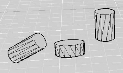
Cylinders are very common in 3D drawing, both for building models and creating holes. Figure 24.6 shows three solid cylinders. The grid helps you to visualize the XY plane. You can draw cylinders with circular or elliptical bases. By specifying the center of the top of the cylinder separately, you can draw it at an angle.
Follow these steps to draw a cylinder:

At the
Specify center point of base or [3P/2P/Ttr/Elliptical]:prompt, specify the center point for a circular cylinder or define the circle by using the 3P, 2P, or Ttr option. You can also choose the Elliptical option to define an ellipse as a base.If you specified a center point, then at the
Specify base radius or [Diameter]:prompt, specify a radius or use the Diameter option to specify the diameter.If you chose the Elliptical option, use the prompts to define the elliptical base.
At the
Specify height or [2Point/Axis endpoint]:prompt, specify the height by dragging, entering a value, or using the 2Point option. You can create a tilted cylinder by using the Axis endpoint option to specify the center of the other end of the cylinder. (By default, the Axis endpoint is a relative coordinate, based on the center of the base.)
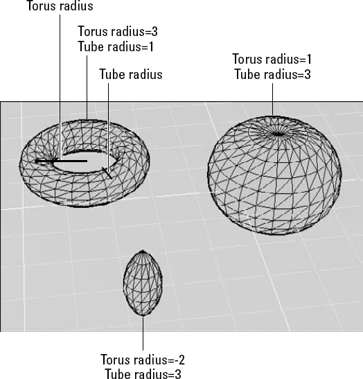
A torus is a solid 3D donut. Figure 24.7 shows some examples with the parts of the torus labeled. You can make some unusual shapes by varying the torus and tube radii. If the torus radius is negative and the tube radius is larger than the absolute value of the torus radius (for example, −2 and 3), you create a lemon (or football) shape. If the tube radius is larger than the torus radius, you create a puckered ball (or apple) shape. (You cannot get such unusual shapes by using the Torus shape on the Surfaces toolbar.)
To create a torus, follow these steps:

At the
Specify center point or [3P/2P/Ttr]:prompt, specify the center of the torus (the center of the hole). You can also use the 3P, 2P, or Ttr option to define a circle as the basis for the torus.At the
Specify radius or [Diameter]:prompt, specify the radius of the entire torus or use the Diameter option to specify the diameter.At the
Specify tube radius or [2Point/Diameter]:prompt, specify the radius of just the tube or use the Diameter option to specify the tube's diameter. You can use the 2Point option to pick two points that define the tube radius.
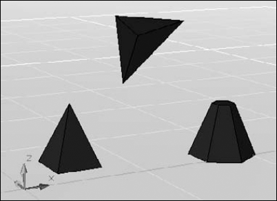
You can draw pyramids with a base of 3 to 32 sides. The prompts for the base are similar to the prompts for the POLYGON command. (For more information on the POLYGON command, see Chapter 6.) A pyramid can come to a point, or you can truncate it. You can also tilt the pyramid. Figure 24.8 shows three variations on the pyramid.
Follow these steps to draw a pyramid:

At the
Specify center point of base or [Edge/Sides]:prompt, specify the center of the base. You can use the Edge option to define an edge, or the Sides option to specify the number of sides.At the
Specify base radius or [Inscribed]:prompt, drag to specify the radius or enter a value. You can use the Inscribed (or Circumscribed) option to change whether the radius is inscribed (based on the base points) or circumscribed (based on the base side midpoints).At the
Specify height or [2Point/Axis endpoint/Top radius]:prompt, drag to specify the height or enter a value. Use the 2Point option to specify the height by picking two points. Use the Axis endpoint to specify the tip. If it isn't directly over the base's center, you tilt the pyramid. Use the Top radius to truncate the pyramid; drag or enter a value for the top's radius and then enter the height of the pyramid.
Note
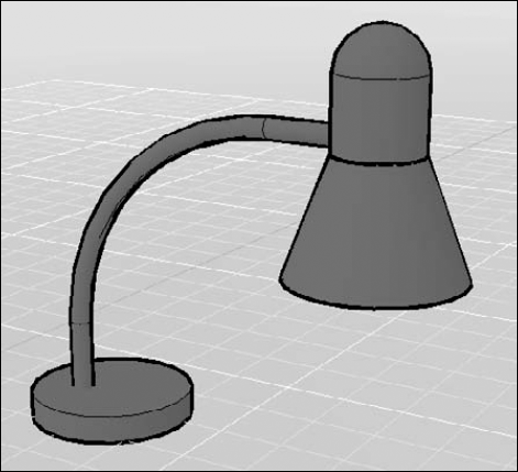
The drawing used in the following exercise on drawing basic solids, ab24-a.dwg, is in the Drawings folder on the DVD.
STEPS: Drawing Basic 3D Solids
Open
ab24-a.dwgfrom the DVD.Save the file as
ab24-01.dwgin yourAutoCAD Biblefolder. Turn on Object Snap. Set running object snaps for Quadrant and Center. In this exercise, I assume that you have dynamic input on, set to the default of relative coordinates.
Specify center point of base or [3P/2P/Ttr/Elliptical]:
7,6.5Specify base radius or [Diameter] <3.0000>:
3Specify height or [2Point/Axis endpoint] <1.0000>:1Repeat the CYLINDER command. Zoom closer to the top end of the lamp's arm and change the viewpoint so that you can see the end circle more clearly. Follow the prompts:
Specify center point of base or [3P/2P/Ttr/Elliptical]:
2pSpecify first end point of diameter:Choose the bottom quadrant of the top end of the lamp's arm. Specify second end point of diameter:3,0Specify height or [2Point/Axis endpoint] <17.2980>:Move the cursor upward and enter2.5.Specify center point or [3P/2P/Ttr]:
2pSpecify first end point of diameter:Pick the left quadrant of the top of the cylinder that you just drew. Specify second end point of diameter:Pick the right quadrant of the top of the cylinder that you just drew.
Specify center point of base or [3P/2P/Ttr/Elliptical]:
Pick the center of the bottom of the cylinder. Specify base radius or [Diameter] <1.5000>:Pick any quadrant on the edge of the cylinder's bottom edge. Specify height or [2Point/Axis endpoint/Top radius] <4.0000>:tSpecify top radius <3.0000>:3Specify height or [2Point/Axis endpoint] <4.0000>: Move the cursor downward and enter4.Choose View tab

Choose Home tab
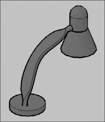
Save your drawing. It should look like Figure 24.9.
The EXTRUDE command creates solids from closed 2D objects, and surfaces from unclosed 2D objects. The result is similar to adding thickness to a 2D object (discussed in Chapter 21) or using the TABSURF command (see Chapter 23). You can also extrude the face of an existing solid, as I explain later in this chapter. You can extrude lines, arcs, elliptical arcs, 2D polylines, circles, ellipses, splines, 2D solids, planar surfaces, and regions. You can use the REGION command to create one object from several objects for this purpose. You can select several objects and extrude them at one time. Figure 24.10 shows several extruded solids.
When you extrude a circle to make a cylinder, for example, what should happen to the circle? Do you want to delete it because you want to turn it into a cylinder, or do you want to keep it in case your cylinder isn't just right and you need to use the circle again? The DELOBJ system variable determines whether objects used by the EXTRUDE command (as well as the REVOLVE, LOFT, SWEEP, and others) to make other objects are retained. By default, certain source objects are deleted. Therefore, when you use a 2D object to make a solid, the 2D object is deleted.
Tip
Put source objects on a separate layer. Set DELOBJ to 0 (zero) to keep objects used to create other objects. When you're done, turn off the layer containing your source objects.
The DELOBJ system variable has the following options:
Retains all source objects.
Deletes profile curves. For example, if you use a circle to create a cylinder, the circle is deleted. Cross-sections and guides used with the SWEEP command are also deleted. However, if you extrude along a path, the path is not deleted. This is the default option.
Deletes all defining objects, including paths.
Prompts to delete profile curves. This is like 1, but you get a prompt so you can choose.
Prompts to delete all defining objects. This is like 2, but you get a prompt.
When you extrude an object, by default you extrude it perpendicular to the object. However, you can also taper the extrusion, as in the extruded rectangle on the right in Figure 24.10. A positive angle tapers the object inward. A negative angle tapers the object outward so it gets wider in the direction of the extrusion.
Note
Don't taper the object too much. If the taper angle results in the object coming to a point before its full height, AutoCAD cannot create the solid.
You can extrude the object by specifying a height of extrude, a direction by specifying two points, or along a path. A path can be a line, circle, arc, ellipse, elliptical arc, polyline, spline, or even a helix. The path object must be in a different plane than the original object. Not all paths are suitable for extruding objects. In the following situations, the extrusion may not work. The path should not be:
Too close to the original object's plane
Too complex
Too tightly curved or bent for the size of the original object
Here are the steps for creating an extruded solid:
Draw the object that you want to extrude. If you want to extrude along a path, draw the path object in a different plane from the source object.

Select the object or objects to extrude.
At the
Specify height of extrusion or [Direction/Path/Taper angle] <3.5226>:prompt, specify the height of the extrusion (drag or enter a value). Use the Path option to extrude along a path object; just select the path object. The Direction option is similar to the Path option, except that you specify two points to indicate the path. Use the Taper angle option to enter a taper angle.
Note
The drawing used in the following exercise on creating extruded solids, ab24-b.dwg, is in the Drawings folder on the DVD.
STEPS: Creating Extruded Solids
Open
ab24-b.dwgfrom the DVD.Save the file as
ab24-02.dwgin yourAutoCAD Biblefolder. Make sure that Object Snap is on. Set running object snaps for Endpoint and Midpoint. This is a small mounting angle, shown in an edge view.The angle is made up of lines and arcs. To extrude it, you need to change it into a polyline or region. To change it into a polyline, choose Home tab
Select polyline or [Multiple]:
Select any object on the angle. Object selected is not a polyline Do you want to turn it into one? <Y>Enter an option [Close/Join/Width/Edit vertex/Fit/Spline/Decurve/Ltype gen/Undo]:Right-click and choose Join. Select objects:Use a window to select all the objects in the angle. Select objects:Enter an option [Open/Join/Width/Edit vertex/Fit/Spline/Decurve/Ltype gen/Undo]:Right-click and choose Enter.
Choose Home tab
Save your drawing. It should look like Figure 24.11.
The mounting angle should have two holes in it. You would create the holes by using the SUBTRACT command, which I cover later in this chapter.
The SWEEP command is similar to the EXTRUDE command, but it concentrates on using paths to define the direction of the extrusion.
The SWEEP command has some great tricks up its sleeve:
You can draw the source object on the same plane as the path. You don't even have to place the source object on the path. The SWEEP command figures out the center of the source object. (You can use the Base point option to specify the base point for the source object.)
You can twist the object along the path.
You can scale the source object.
If the source object is a closed object, like a circle, you get a solid; if it's open, you get a swept surface.
The DELOBJ system variable determines what happens to the original objects; for more information, see the explanation in the previous section. Figure 24.12 shows some swept solids.
To create a swept solid or surface, follow these steps:
Draw the path that you want to sweep along.
In the same plane as the path, draw the object or objects that you want to sweep.

At the
Select objects to sweep:prompt, select the object or objects that you drew.At the
Select sweep path or [Alignment/Base Point/Scale/Twist]:prompt, select the path.Use the Alignment option if you don't want to align the object perpendicular to the path. By default, the SWEEP does so; for this reason, you don't have to set up the path and the object in different planes.
Use the Base Point option to specify a base point on the objects to be swept, to determine the point on that object that actually lies along the path.
Use the Scale option to scale the object before sweeping it.
Use the Twist option to twist the object along the path. For example, if you specify 180°, the object twists that much from the beginning to the end of the path. This option has a suboption, Bank, that allows you to specify if you want the object to also rotate in the 3D direction when you use a 3D sweep path (a 3D polyline, 3D spline, or helix).
Note
The drawing used in the following exercise on creating swept solids, ab24-c.dwg, is in the Drawings folder on the DVD.
STEPS: Creating Swept Solids
Open
ab24-c.dwgfrom the DVD. This is the same drawing that was used for the exercise on drawing basic shapes; however, this time the desk lamp is missing its arm. A path is already drawn on theconstlayer.Save the file as
ab24-03.dwgin yourAutoCAD Biblefolder. If necessary, change the visual style to 3D Wireframe (choose Home tabMake the
constlayer current. Draw a circle anywhere with a radius of 0.375 (a diameter of 0.75).Switch to the
objectlayer.
Select objects to sweep:
Select the circle. Select objects to sweep:Select sweep path or [Alignment/Base point/Scale/Twist]:Select the arm (the polyline).Turn off the
constlayer.Save your drawing. Look back to Figure 24.9 to see what the lamp looks like.
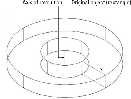
The REVOLVE command revolves a profile around an axis. If the profile is closed, the result is a solid; if it's open, the result is a revolved surface. (When the profile is open, the result is like the REVSURF command, which I explain in Chapter 23.) You can revolve lines, arcs, elliptical arcs, 2D polylines, circles, ellipses, splines, 2D solids, planar faces, and regions.
The DELOBJ system variable affects whether the original objects are deleted. See the discussion on this system variable earlier in this chapter in the section "Managing objects used to make other objects."
Figure 24.13 shows a solid created by revolving a rectangle around a line. (You can also create this solid by drawing two circles, extruding them into cylinders, and then subtracting the smaller cylinder from the larger one — it just depends on which technique you're more comfortable with.)
To create a revolved solid, follow these steps:

At the
Select objects to revolve:prompt, select one or more objects.At the
Specify axis start point or define axis by [Object/X/Y/Z] <Object>:prompt, you can pick two points to create an axis of revolution. You can also select an object as an axis. Use the X, Y, or Z option to revolve the object around the respective axis.At the
Specify angle of revolution or [STart angle] <360>:prompt, press Enter to revolve the object 360 degrees or type an angle, either positive or negative. You can use the STart angle option to specify a start and end angle; for example, you can start at 45 degrees and end at 90 degrees.
As with the REVSURF command, you need to determine the positive direction of rotation if you're revolving less than 360 degrees. (Of course, it may be quicker to try one way and just do it the other way if it doesn't turn out right.) Here's how to figure it out:
First determine the positive direction of the axis. If you specify start and endpoints, the positive axis direction goes from the start point to the endpoint. If you pick an object, the positive axis direction goes from the pick point to the other endpoint. If you choose the X, Y, or Z axis, the positive direction is obvious.
Point your right thumb in the positive direction of the axis.
Look at the curl of your fingers on that hand. That's the positive direction of rotation.
The LOFT command creates a solid or surface that is interpolated from a series of profiles, or cross-sections. Open profiles create a surface; closed profiles create a solid. Figure 24.14 shows some lofted solids.
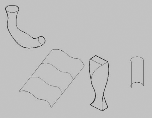
Figure 24.14. Two solid and two surface lofted objects. On one of the surfaces, you can see the source cross-sections (splines).
The difficult part of lofting is drawing and placing the source cross-sections to get the result that you want. To create a lofted surface or solid, follow these steps:
Draw a series of closed (for a solid) or open (for a surface) profiles. You can start with one and then copy it to nearby locations on the path that will run centrally along the lofted object. You can then modify the copies as necessary. These cross-sections become the basis for the lofted object. You need at least two cross-sections.
If you want to control the sides of the loft (generally for surfaces), draw guides on each side of your cross-sections. Guides must start at the first cross-section, end at the last cross-section, and intersect each cross-section.
If you want to specify a path through the middle of the loft, draw a path object. The path must intersect the plane of each cross-section. The resulting lofted model runs the length of the path.

At the
Select cross-sections in lofting order:prompt, choose each cross-section in order, and then end selection.At the
Enter an option [Guides/Path/Cross sections only] <Cross sections only>:prompt, press Enter to accept the default, which uses the cross-sections only to define the loft. Use the Guides option to select guides you have drawn. Use the Path option to select a path you have drawn.If you chose the
Cross sections onlyoption, the Loft Settings dialog box opens. You use this dialog box to fine-tune the definition of the loft and specifically to control how the loft is curved at its cross-sections.Ruled. Creates a straight (ruled) solid or surface between the cross-sections and sharp edges at the cross-sections.
Smooth Fit. Creates a smooth solid or surface between the cross-sections and sharp edges at the first and last cross-sections.
Normal to. Defines which cross-sections the solid or surface is perpendicular (normal) to — the start, end, both start and end, or all cross-sections.
Draft Angles. Controls the draft angle (the beginning and ending angles) at the first and last cross-sections. This is similar to specifying start and end tangents on a spline. A 0° angle is the default: normal to the cross-section's plane in the direction of the next cross-section. A 180° angle goes outward, away from the cross-section. You also define a magnitude, which is the relative distance that the solid or surface goes before bending to the next cross-section. In other words, if you use a 180° angle, a large magnitude creates a large bulge.
Close Surface or Solid. Closes the model.
With all these options, you may need to experiment a little. Keep the Preview Changes check box selected and watch what happens as you change the settings. After you create a loft, you can select it and make changes in the Properties palette; again, you can see the results of your changes immediately.
Note
The drawing used in the following exercise on creating lofted solids, ab24-d.dwg, is in the Drawings folder on the DVD.
STEPS: Creating Lofted Solids
Open
ab24-d.dwgfrom the DVD. This is the same drawing that was used for the exercise on drawing swept solids; again, the desk lamp's arm is missing, but it has some cross-sections (on theconstlayer) that you can use to create a lofted solid. Theobjectlayer should be current.Save the file as
ab24-04.dwgin yourAutoCAD Biblefolder. If necessary, change the visual style to 3D Wireframe (choose Home tab
Select cross sections in lofting order:
Select the bottom-most cross-section (a circle). Select cross sections in lofting order:Continue to select all the other cross-sections, one at a time, moving upward until you select the circle closest to the head of the lamp. Press Enter to end selection. Enter an option [Guides/Path/Cross sections only] <Cross sections only>:cThe Loft Settings dialog box opens. Click OK to accept all the defaults and create the lofted solid.
Turn off the
constlayer.Change the visual style to Conceptual (choose Home tab
Save your drawing. Use the 3D Orbit override (Shift+mouse wheel) to change to a view that shows the arm more clearly. It should look like Figure 24.15.
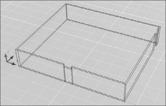
The POLYSOLID command is helpful to architects who want to draw walls in 3D. Using POLYSOLID is like drawing a polyline with a width, or a multiline. You simply draw in plan view from point to point, but the result is a swept solid, using the width and height you specify. You can also convert existing 2D objects — lines, arcs, 2D polylines, and circles — into polysolids. Figure 24.16 shows a simple layout, drawn by using polysolids.
Follow these steps to draw a polysolid:
If you want to convert a 2D object, draw the object or open a drawing containing an existing 2D object.

At the
Specify start point or [Object/Height/Width/Justify] <Object>:prompt, start by choosing the Height option.At the
Specify height <8'-0">:prompt, enter a height.The original prompt returns. Choose the Width option. At the
Specify width <0'-6">:prompt, enter a width.Again the original prompt returns.
If you want to convert an existing object, choose the Object option (you can just press Enter because it's the default option). At the
Select object:option, select the 2D object to complete the polysolid.If you want to draw a new polysolid, specify the start point and continue to specify segments as you would for a polyline. After you specify the first point, you can use the Arc option to create arcs. The prompts are like those for the PLINE command, but you have fewer options. The arc starts tangent to the previous segment. You can specify the direction or the second point for more control.
You can use the Close option to close the polysolid. You can also use the Justify option to determine whether the polysolid is centered around the points you specify (the default), left-justified (your points are to the left side if you're drawing upward), or right-justified.
Note
The drawing used in the following exercise on creating polysolids, ab24-e.dwg, is in the Drawings folder on the DVD.
STEPS: Creating Polysolids
Open
ab24-e.dwgfrom the DVD. This drawing contains two polylines — one to turn into a polysolid and one to create a door gap.Save the file as
ab24-05.dwgin yourAutoCAD Biblefolder. If necessary, change the visual style to 3D Wireframe (choose Home tabSet the value of the DELOBJ system variable to 0 (zero) so that you don't delete the source object.

Specify start point or [Object/Height/Width/Justify] <Object>:
hSpecify height <0'-4">:8'Specify start point or [Object/Height/Width/Justify] <Object>:wSpecify width <0'-0 1/4">:6Specify start point or [Object/Height/Width/Justify] <Object>:to choose the Object option. Select object: Select the larger polyline.Select the new polysolid and change its layer to
Walls.Zoom into the gap for the door. Repeat the POLYSOLID command. Follow the prompts:
Specify start point or [Object/Height/Width/Justify] <Object>:
jEnter justification [Left/Center/Right] <Right>:rSpecify start point or [Object/Height/Width/Justify] <Object>:hSpecify height <8'-0">:7'Specify start point or [Object/Height/Width/Justify] <Object>:Pick the front endpoint on the left side of the gap. Specify next point or [Arc/Undo]:Pick the front endpoint on the right side of the gap. Specify next point or [Arc/Undo]:To create a gap for a side door, you need to create a surface and slice the solid with the surface. (I discuss slicing later in this chapter.) Switch to the
2Dlayer. Choose Home tabChoose Home tab
Select objects to slice:
Select the first polysolid that you created. Select objects to slice:Specify start point of slicing plane or [planar Object/Surface/Zaxis/View/XY/YZ/ZX/3points] <3points>:sSelect a surface:Select the extruded surface. Select solid to keep or [keep Both sides] <Both>: Pick anywhere on the main portion of the polysolid wall.Note
If you find that this step doesn't work properly, undo it and redo the step, this time choosing the Both option. Then erase the smaller section of the polysolid in the door opening.
Make the
Wallslayer current. Turn off the2Dlayer.Save your drawing. It should look like Figure 24.17. If you want, add a polysolid over the front door and rotate the front door to open it. You should also change the DELOBJ system variable back to its original value.
You can directly manipulate solids and meshes (discussed later in this chapter) in several ways that don't involve executing a command. These methods are grip-editing, selecting sub-objects (faces, edges, and vertices), and using the move, rotate, and scale tools (called gizmos).
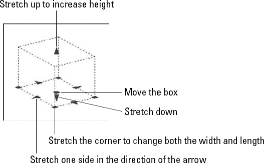
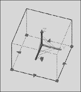
You can grip-edit solids in several ways. When you select them, they show grips that allow you to stretch them in all directions. Figure 24.18 shows the grips for a solid box. The triangular grips stretch objects in the direction of the arrow. The square grips also stretch objects, usually at a corner. One grip at the center just moves the object.
Note
You can also use grips to move, rotate, scale, and mirror solids. I cover grip-editing in Chapter 10 for 2D drawings; the same principles apply for 3D drawings.
You can select sub-objects and edit them. A sub-object is the face, edge, or vertex of a solid. A subcomponent of a composite solid — one that you used UNION, SUBTRACT on — is also a sub-object. You can select more than one sub-object, whether on one solid or several solids.
To grip-edit a sub-object, follow these steps:
You can press Ctrl and click to select a sub-object when you select objects for the MOVE, ROTATE, SCALE, or ERASE command. You can press Ctrl and drag a selection or crossing window to select multiple sub-objects.
If you want to select the back face of a solid, you can cycle through the faces by pressing and holding Ctrl and repeatedly pressing the Spacebar. Just as you can press Shift and pick to remove any object from a selection set, you can remove a sub-object from a selection set by pressing and holding Ctrl and pressing Shift while you pick a sub-object.
Note
To help make selecting sub-objects easier, you can create a filter that specifies which type of sub-object you want to select: face, edge, or vertex. Click Home tab
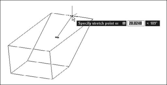
Figure 24.19 shows the process of grip-stretching an edge of a box.
Tip
The LEGACYCTRLPICK system variable lets you return to the older use of Ctrl+click, which was to cycle through overlapping objects for easier selection. By default, this system variable is set to 0, which allows you to select sub-objects on 3D solids. Change its value to 1 to use Ctrl+click to cycle through objects. When set to 1, you can't use Ctrl+click to select sub-objects.
When moving, rotating, and scaling in 3D, it's often hard to visualize the direction in which you want the object to go. Three tools (called gizmos) help with these tasks.
You can use the regular MOVE command to move objects in any direction, X, Y, or Z, but entering the coordinates can be awkward. Instead, you can use the Move gizmo, with or without executing the 3DMOVE command, to interactively move objects in 3D space. Figure 24.20 shows the Move gizmo.
To use the Move gizmo by itself, follow these steps:
Select an object, with no command active. If you have a 3D visual style active (anything except 2D Wireframe), the Move gizmo automatically appears. (By default, the Quick Properties palette appears nearby; close it if it interferes with your view.)
Note
If you don't want the Move gizmo to display automatically, set the GTAUTO system variable to 0 (zero).
Note
The DEFAULTGIZMO system variable determines which gizmo appears by default. You can set this system variable by choosing Home tab
Pass the cursor over any grip (but not an arrow); the Move gizmo jumps to that grip. This temporarily places the origin of the UCS at that point and sets the base point for the move operation.
Note
In any 3D visual style, the X axis of the UCS icon is red, the Y axis is green, and the Z axis is blue. The Move gizmo uses the same colors to indicate the same directions.
You can now choose one of three setups to move the selected object:
To move the selected object in any direction. Drag on the grip itself. This is no different from dragging without the Move gizmo.
To constrain the selected object along one axis. Pass the cursor over that axis until it turns yellow and you see a line extending to the edge of the screen on either side. Click that axis; now you can move the object only along that axis line. Drag the object in the positive or negative direction along the line. You can use direct distance entry to move the object a specific distance, or just click where you want the grip to be.
To constrain the selected object along one plane. Pass the cursor over the right-angle indicator at the intersection of any two axes, until it turns yellow. Click that right-angle indicator; now you can move the object only in that plane. Move the object in the desired direction. You can enter a relative coordinate or click where you want the grip to be.
Note
Once you constrain the move, you can press the Spacebar to cycle among the three gizmos, retaining the directional constraint you specified.
Choose Home tab
Note
If you're using the 2D Wireframe visual style, the command switches you temporarily to the 3D Wireframe visual style. When you're done, the 2D Wireframe visual style returns.
At the
Specify base point or [Displacement] <Displacement>:prompt, the Move gizmo appears.To use the base point/second point method, specify a base point. You can now constrain movement to an axis or plane as described just previously in this section. Then specify a second point to move the object.
To use the displacement method, enter a displacement as an X,Y or polar coordinate. At the
Specify second point or <use first point as displacement>:prompt, press Enter to move the object and end the command. In this situation, you don't use the Move gizmo because you are specifying the movement by entering coordinates.
You have a chance to use the 3DMOVE command later in this chapter in the exercise on Extending Objects in 3D.
The Rotate gizmo lets you interactively rotate in 3D. You can rotate freely or constrain rotation around one axis. You can use it with or without the 3DROTATE command. To use it alone, follow these steps:
Select an object, with no command active. If you have a 3D visual style active (anything except 2D Wireframe), the Rotate gizmo automatically appears. (By default, the Quick Properties palette appears nearby; close it if it interferes with your view.)
Note
If one of the other gizmos appears, right-click the gizmo and choose Rotate from the shortcut menu. In the previous explanation of the Move gizmo, I explain how to specify which gizmo appears by default.
Pass the cursor over any grip (but not an arrow); the Rotate gizmo jumps to that grip. This temporarily places the origin of the UCS at that point and sets the base point for the move operation.
To constrain the selected object along one axis, pass the cursor over that axis's handle (a circle) until it turns yellow and you see a line extending to the edge of the screen on either side, as shown in Figure 24.21. Click that axis; now you can rotate the object only along that axis. Drag the object along the circle. You can enter a value to rotate the object a specific angle, or just click when the object is at the desired angle.
Note
After you constrain the rotation, you can press the Spacebar to cycle among the three gizmos, retaining the directional constraint you specified.
You can also use the 3DROTATE command. Follow these steps:

Note
If you are in 2D Wireframe visual style, this command temporarily changes you to 3D Wireframe. You need to be in a nonorthogonal view to use 3DROTATE.
Select objects. The Rotate gizmo appears, as shown in Figure 24.21.
At the
Specify base point:prompt, specify the base point for the rotation. The Rotate gizmo jumps to the base point.At the
Pick a rotation axis:prompt, hover the cursor over the ribbon that matches the axis around which you want to rotate. It turns yellow and you see an axis line, as shown in Figure 24.21. Click the yellow ribbon.At the
Specify angle start point or type an angle:prompt, you can simply enter the rotation angle that you want, or pick two points to specify the angle.
I discuss another way to rotate, the ROTATE3D command, later in this chapter. There you'll find an exercise that uses the Rotate gizmo.
The Scale gizmo, shown in Figure 24.22, lets you interactively scale in 3D. Most 3D objects you can scale uniformly along all three axes; however, you can scale meshes along one axis or a plane that you choose. I discuss meshes later in this chapter.
You can use the Scale gizmo with or without the 3DSCALE command. To use it alone, follow these steps:
Select an object, with no command active. If you have a 3D visual style active (anything except 2D Wireframe), the Scale gizmo automatically appears. (By default, the Quick Properties palette appears nearby; close it if it interferes with your view.)
Note
If one of the other gizmos appears, right-click the gizmo and choose Scale from the shortcut menu. In the previous explanation of the Move gizmo, I explain how to specify which gizmo appears by default.
Pass the cursor over any grip (but not an arrow); the Scale gizmo jumps to that grip. This temporarily places the origin of the UCS at that point and sets the base point for the move operation. (Meshes only have one grip.)
Tip
To move the Scale gizmo to a location not on a grip, right-click and choose Relocate Gizmo. You can then use an object snap to specify any other location.
For meshes only, you can constrain the scale along an axis or plane. Do one of the following:
To constrain the selected object along one axis. Pass the cursor over that axis until it turns yellow and you see a line extending to the edge of the screen on either side. Click that axis; now you can scale the object only along that axis. Drag the object along the axis and click when the object is at the desired size or enter a scale factor.
To constrain the selected object along a plane. Pass the cursor over one of the lines that join the axes. For example, to scale along the XY plane, pass the cursor over the line that runs from the X axis to the Y axis. The line turns yellow as do the axis names. Click that line; now you can scale the object only along the specified plane. Drag in the direction you want to scale or enter a scale factor.
Note
Once you constrain the scale, you can press the Spacebar to cycle among the three gizmos, retaining the directional constraint you specified.
Tip
It can be hard to see the lines between the planes if the axes are facing away from you. If so, you can press Shift and drag with the mouse wheel to change the 3D view.
You can also use the 3DSCALE command. Follow these steps:

Note
If you are in 2D Wireframe visual style, this command temporarily changes you to 3D Wireframe. You need to be in a nonorthogonal view to use 3DSCALE.
Select objects. The Scale gizmo appears, as shown in Figure 24.22.
At the
Specify base point:prompt, specify the base point for the scale operation.At the
Pick a scale axis or plane:prompt, click an axis or plane line. Remember that you can only pick a scale axis or plane for mesh objects; you can only scale other 3D objects uniformly.At the
Specify scale factor or [Copy/Reference] <1.000>:prompt, enter a scale factor or drag to the desired scale.
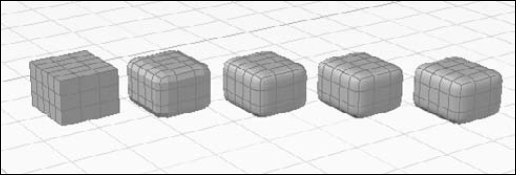
Meshes are 3D shapes that allow you to create organic, flexible models. Meshes can be either surfaces or solids. Meshes contain divisions that tile the mesh into faces. This division of the model into tiles is called tessellation. The tessellation divisions bound the edges of each face. You have detailed control over each face, edge, and vertex in the mesh. Figure 24.23 shows three solid meshes.
Note
Mesh shapes are new for AutoCAD 2010. They offer enhanced capabilities for creating complex and flexible shapes.
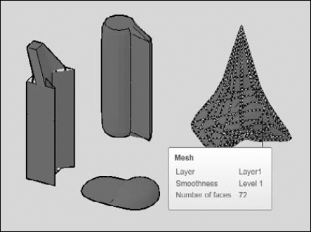
Figure 24.23. Several meshes, shown in Conceptual visual style. When the cursor is over a mesh, you can see the mesh faces and tessellations.
Just as you can create basic smooth solids, called primitives, you can create mesh primitives. The same shapes are available and the prompts are almost identical. To create a mesh primitive, choose Mesh Modeling tab
As mentioned in Chapter 23, by default, the REVSURF, RULESURF, EDGESURF, and TABSURF commands create meshes. These commands are also available in the Primitives panel of the Mesh Modeling tab.
The power of meshes becomes apparent when you edit them; the editing tools allow you to mold shapes in ways that you can't with surfaces or smooth solids. The following sections explain how to edit meshes.
When you select a mesh, you see only one grip. However, by selecting sub-objects, you can easily use grips to stretch, move, rotate, scale, or mirror parts of the mesh. (See the "Selecting sub-objects" section earlier in this chapter for more information.) In this way, you can edit one or more faces, edges, and vertices. In the same way, you can use the Move, Rotate, and Scale gizmos to edit entire meshes or portions of them.
When you refine a mesh, you increase the number of faces and, therefore, tessellations that the mesh contains. At the same time, each face becomes smaller, allowing you to make more localized changes to the mesh. You can refine an entire mesh or even an individual face. When you refine an individual face, you divide it into multiple faces. In order to refine a mesh, it must have a smoothness level of 1 or higher.
Refining an object resets its smoothness level to 0, but doesn't change its shape. Therefore, the object continues to look rounded, but you can't reduce its smoothness.
Refining an individual face subdivides the face into new faces, but does not reset the base level of smoothness. This method confines the changes to a smaller area and preserves system resources.
You can specify the number of tessellations that a mesh primitive has before you create it. To do so, choose Mesh Modeling tab
At the Specify crease value [Always] <Always>: prompt, press Enter to always crease the sub-object. If you want the crease to apply only at lower smoothing levels, specify a level from 1 to 4. Then the sub-object loses its crease if you smooth above that level. You can select the sub-object and modify the crease value in the Properties palette.
Figure 24.25 on the left shows a mesh primitive box with the top face extruded. In the middle, you see the result after two smoothing operations. On the right, you see the result after creasing the top face of the extrusion.
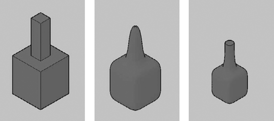
Figure 24.25. To retain a face's sharpness after smoothing a mesh, you can add a crease to the face.
You can uncrease a sub-object; choose Mesh Modeling tab
You can convert smooth surfaces and solids to meshes, and vice versa. Each type of object has its own capabilities and you can take advantage of both by converting from one to the other. Previous sections have described how you can edit meshes. The following sections describe how you can edit smooth solids.
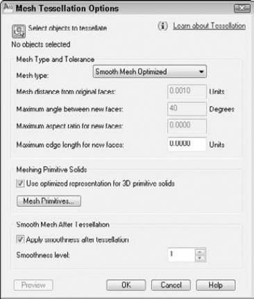
Figure 24.26. The Mesh Tessellation Options dialog box controls the results when you convert 3D solids and surfaces to meshes.
If you want to convert an object right away, click the Select Objects to Tessellate button to return to the drawing. Select the objects.
In the Mesh Type and Tolerance section, you have the following settings:
Mesh Type. Choose a mesh type from the Mesh Type drop-down list. The default, Smooth Mesh Optimized, shapes the faces according to the shape of the mesh object. You can also specify mostly quadrilateral or triangle shapes. The latter two choices don't allow you to apply smoothness during conversion.
Mesh Distance from Original Faces. Sets the maximum deviation of the faces from the shape of the original object. Smaller values result in a more accurate shape, but create more faces. This may slow down performance. The default value is 0.001.
Maximum Angle Between New Faces. Sets the maximum angle between adjacent faces. If you increase the angle, you increase the density of mesh faces in high-curvature areas, and decrease the density in flatter areas. Increase the value if you need to create small details in your model. The default value is 40° and you can set values between 0 and 180.
Maximum Aspect Ratio for New Faces. Sets the maximum height/width ratio for mesh faces. Use this feature to avoid long, skinny faces. The default value, 0, does not limit the aspect ratio. Values greater than 1 specify the maximum ratio that the height can exceed the width. Values less than 1 specify the maximum ratio that the width can exceed the height. A value of 1 creates faces that have the same height and width.
Maximum Edge Length for New Faces. Sets the maximum length of a face's edge. The default value, 0, lets the size of the model determine the size of the faces.
You can check the Use Optimized Representation for 3D Primitive Solids check box to use the values in the Mesh Primitive Options dialog box, discussed in the "Refining a mesh" section earlier in this chapter. Click the Mesh Primitives button to open the Mesh Primitive Options dialog box and make changes there.
You can apply a smoothness level during conversion to a mesh. To do so, check the Apply Smoothness after Tessellation check box and specify the Smoothness Level. The default value is 1, which applies one level of smoothness.
Tip
For the most accurate results when converting, change this value to 0. You can smooth the object afterwards if you want.
Click OK to close the dialog box and specify the settings. If you selected an object, the conversion takes place. Otherwise, choose Mesh Modeling tab
After creating and editing meshes, you may want to convert them to smooth solids. As I explain in the next section, you can combine (union), subtract, intersect, and fillet smooth solids, something that you cannot do with meshes. To use these editing commands on meshes, you need to convert them.
Note
Use the SMOOTHMESHCONVERT system variable to choose whether you want smoothed or faceted solids and whether you want to optimize (merge) coplanar faces. The default value, 0, creates a smooth model and optimizes coplanar faces. A value of 1 creates a smooth model but doesn't optimize faces. A value of 2 creates flattened faces and optimizes coplanar faces. A value of 3 creates flattened faces and does not optimize coplanar faces.
Tip
You can use the DELOBJ system variable (set it to 0) to retain the original mesh, in case you need to redo the operation later. By default, the value is 1, which deletes the original object.
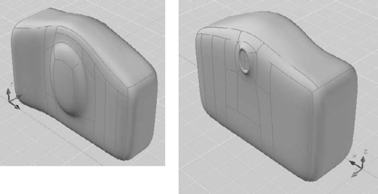
STEPS: Creating and Editing Meshes
Open a new drawing based on the
acad3d.dwttemplate. If you're not in the 3D Modeling workspace, click the Workspace Switching pop-up menu from the right side of the status bar and choose 3D Modeling. This exercise assumes that Dynamic Input settings are set to the default of relative coordinates. (For more information, see Chapter 4.)Save it as
ab24-06.dwgin your AutoCAD Bible folder.Choose Mesh Modeling tab
Choose Mesh Modeling tab
Specify first corner or [Center]:
5,5Specify other corner or [Cube/Length]:85,25Specify height or [2Point] <28.9633>:60Choose Home tab
In the Subobject panel of the Mesh Modeling tab, choose Face from the Subobject Selection Mode drop-down list. Then choose Move Gizmo from the Default Gizmo drop-down list. These choices will help you edit the box.
Press the Ctrl key and click the faces at

Move the cursor over the blue Z axis of the Move gizmo until it becomes yellow, and click. Drag upward a little, and then type 10
From the Subobject Selection Mode drop-down list, choose Edge. Then press Ctrl and select the three edges at

Press Ctrl and select the three edges at


Choose Face from the Subobject Selection Mode drop-down list. Press Ctrl and choose the face at

With the face still selected, pass the cursor over the Z axis until it turns yellow, and click. Then type 1.5
To move the lens upwards, right-click the Scale gizmo and choose Move from the shortcut menu. Pass the cursor over the Z axis until it turns yellow, and click. Then drag upwards a little. Type 8
To extrude the lens, with the lens face still selected, choose Mesh Modeling tab
To work on the eyepiece at the back of the camera, choose Home tab
Press Ctrl and click the top-center face on the back of the camera, where the eyepiece would be, to select that face.
Right-click the Move gizmo, and choose Scale. You want to scale this face in the ZX plane. Place the cursor between the X and Z axes on the gizmo to turn both axes yellow, and click; if this is hard, right-click and choose Set Constraint

The extrusion creates a new, inner face. To push that new face out, select the innermost face and again extrude it outward, this time with a value of 1.

To make the eyepiece smaller, again select the inner face. If the Scale gizmo does not appear, right-click and choose Scale. As you did previously, select the ZX plane. At the prompt, enter .7
To push the eyepiece inward, right-click the Scale gizmo and choose Move to display the Move gizmo. Highlight the green Y axis (it becomes yellow) and click. Drag inward and enter 2

To create realistic objects, you usually need to edit the simple shapes that I have discussed in this chapter. You can create complex solids by adding them, subtracting them, or intersecting them. These processes are called Boolean operations, which in this context means using logical functions, such as addition or subtraction, on objects. You cannot perform Boolean operations on meshes; to do so, first convert them to smooth solids, as described in the previous section of this chapter.
You use the UNION command to add two solids together, making one solid. If the solids are touching, you get a new, unified solid. If the solids are not touching, but rather are completely separate, using UNION is similar to grouping, because you select them as one object. Figure 24.29 shows the union of two solids showing in the 3D Hidden visual style.
Tip
You can also use the UNION command with 2D regions, either for 2D drawings or as a basis for a 3D model.
Tip
When you create complex solids, the original solids are not retained. Setting the DELOBJ system variable to 0 (zero) doesn't work because the original solids have been changed. If you want, you can copy the original objects to another location in the drawing, in case you need to use them again. You can also use UNDO if the result is not what you expected.
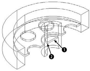
You use the SUBTRACT command to subtract one solid from another. This command is most commonly used to create holes. Figure 24.30 shows the result of subtracting a small cylinder from a larger one.
To subtract solids, follow these steps:

At the following prompt, choose the solid (or region) that you want to subtract from (the one you want to keep):
Select solids, surfaces, and regions to subtract from...
Select objects:
At the following prompt, choose the solid (or region) that you want to subtract (the one you want to get rid of):
Select solids, surfaces, and regions to subtract...
Select objects:
You can also create a solid from the volume that two solids have in common. This volume is called their intersection. Figure 24.31 shows two solids before and after using the INTERSECT command.
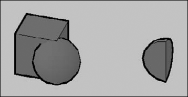
As you can see, you can create some very unusual models this way.
INTERFERE is similar to INTERSECT, except that the original solids remain. AutoCAD creates a third solid from the volume that the two solids have in common. You can also use the INTERFERE command to highlight the common volume of several pairs of solids.
Figure 24.32 shows a solid that was created by using INTERFERE, as well as the Interference Checking dialog box, which opens after you select objects.
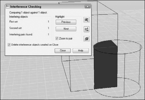
INTERFERE is useful when you have a number of interfering solids. This command enables you to divide the selection set of solids into two sets so that you can compare one against the other. For example, you can compare a box with three other solids by putting the box in one set and the other three solids in the other set.
Tip
You can use INTERFERE for troubleshooting and visualizing a complex drawing. For example, you can use INTERFERE to determine which solids need to be subtracted from other solids. The new objects are created on the current layer. You can change the current layer before using INTERFERE to help you more clearly distinguish the new solid that you create.
To use INTERFERE, follow these steps:
Choose Home tab
At the
Select first set of objects or [Nested selection/Settings]:prompt, select objects. If you want to compare only two objects, you can put them both in the first set. Otherwise, select solids for the first set and press Enter to end object selection.At the
Select second set of objects or [Nested selection/checK first set] <checK>:prompt, select the second set of objects and press Enter to end object selection. If you don't want a second set, press Enter to check the solids. The Interference Checking dialog box opens and the display zooms in to the model, shading the interference and showing the rest of the model in wireframe, as shown in Figure 24.32.If you have more than one interference, click the Next button to display the next one. You can use the Zoom, Pan, and 3D Orbit buttons to adjust your display. Then press Esc to return to the dialog box.
If you want to keep the interference solid after you close the dialog box, uncheck the Delete Interference Objects Created on Close check box.
Click Close when you're done.
Note
The drawing used in the following exercise on creating complex solids, ab24-f.dwg, is in the Drawings folder on the DVD.
STEPS: Creating Complex Solids
Open
ab24f.dwgfrom the DVD.Save the file as
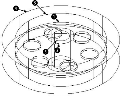
ab24-07.dwgin yourAutoCAD Biblefolder. Make sure that Object Snap is on. Set running object snaps for Endpoint, Midpoint, and Center. This drawing is measured in millimeters. The solids have been created by drawing circles, using EXTRUDE, and moving the solids to the proper Z coordinate. The result is shown in Figure 24.33.
Select solids, surfaces, and regions to subtract from... Select objects:
Select the central plate atin Figure 24.33. Select objects:Right-click. Select solids, surfaces, and regions to subtract... Select objects: Select the six circles arrayed around the plate. Right-click to end selection.To create the central tube, repeat the SUBTRACT command. Follow the prompts:
Select solids, surfaces, and regions to subtract from... Select objects:
Select the outer tube at. Select objects:
Right-click. Select solids, surfaces, and regions to subtract... Select objects: Select the inner tube at. Right-click to end selection.
To "carve out" the central disk, again repeat the SUBTRACT command. Follow the prompts:
Select solids, surfaces, and regions to subtract from... Select objects:
Select the outer circle at. Select objects:Right-click. Select solids, surfaces, and regions to subtract... Select objects: Select the inner circle at. Right-click to end selection.
Change the visual style to 3D Hidden (choose Home tab

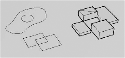
The PRESSPULL command finds closed areas, creates a region, and then lets you extrude or "press" a hole in that region. In addition to any enclosed area that you could hatch, you can press/pull segmented faces of 3D solids. For example, in Figure 24.35, you can press/pull the following:
All the enclosed objects, such as the closed spline, the circle, and the rectangles.
The area enclosed by the overlapping rectangles.
The triangular area on the box created by drawing a line across the top face.
The space in the middle of the four touching smooth solid (but not mesh) boxes, which does not contain any objects.
You can use the PRESSPULL command on any face of a solid. To use the command on a 2D object, you need to move the UCS to the plane of the boundary, as if you were hatching the area.
1 loop extracted.
1 Region created.
You can now move the cursor up or down in either direction to press or pull the region. You can click when you like what you see, or enter a value for the height. (You can usually click and drag in one action, but sometimes AutoCAD takes some time to calculate the region; in that case, click, wait a second, and then move the cursor up or down.)
Because AutoCAD doesn't retain source objects when you use the UNION, SUBTRACT, or INTERSECT command, it would be nice to have a way to modify the original objects separately. Solid history does just that.
Note
The SOLIDHIST system variable controls whether the history is maintained in the drawing. By default, this system variable is on, set to 1.
You can also display the object's history by selecting the object and setting the Show History item in the Properties palette to Yes. For example, if you used a cylinder to make a hole in a box by using the SUBTRACT command, when you show the history, you see the original cylinder again. This display lasts even when you deselect the object, until you change the setting in the Properties palette.
More important, you can use solid history to edit components of a complex solid. For example, you can move or resize a hole or one part of two objects that you combined. To work with one component of a complex solid, press the Ctrl key as you pass the cursor over the object. The individual component is highlighted. Click to display grips for grip-editing. I explain how to select individual components (sub-objects) and grip-edit solids earlier in this chapter.
The BREP command converts 3D solids into boundary representation (BREP) solids. This process deletes a solid's history and you can no longer grip-edit the solid or change its properties in the Properties palette. BREP is available on the command line only.
Note
The drawing used in the following exercise on using PRESSPULL and solid history, ab24-g.dwg, is in the Drawings folder on the DVD.
STEPS: Using PRESSPULL and Solid History
Open
ab24-g.dwgfrom the DVD.Save the file as
ab24-08.dwgin yourAutoCAD Biblefolder. This is the base of the lamp that was used for several exercises earlier in this chapter. There is a circle on theconstlayer at the top of the base. If necessary, change the visual style to 3D Wireframe (choose Home tab
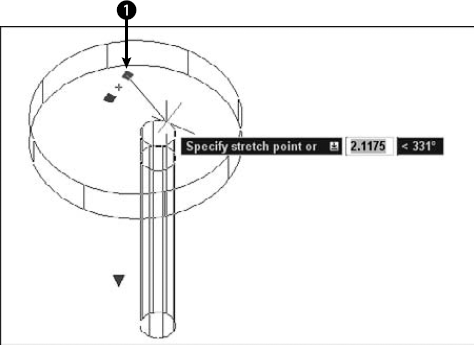
Choose Home tab
Press the Ctrl key and pass the cursor over the center of the new hole. When you see the long cylinder that you originally pressed, click. You now see some grips.
Click the grip at
Deselect the object.
Save your drawing.
In many drawings, you need to show a cross-section of your models. A cross-section displays the inside of a 3D object. The SECTION, SECTIONPLANE, and SLICE commands create cross-section views of your 3D models.
The SECTION command creates a 2D region from a cross-section of a 3D model along a plane that you specify. The original objects are left untouched. Figure 24.37 shows a region created by using the SECTION command.
Tip
The SECTION command creates the region on the current layer. Switch to a layer with a contrasting color from the object's layer so that the region is clearly visible.
To use the SECTION command, enter section on the command line. Select the object that you want to section. AutoCAD displays the Specify first point on Section plane by [Object/Zaxis/View/XY/YZ/ZX/3points] <3points>: prompt. Use these options to define the plane of the cross-section. Table 24.1 explains how to use the options.
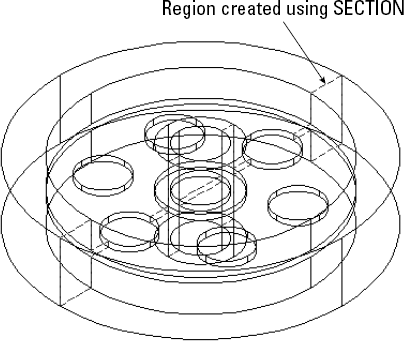
Table 24.1. SECTION Options
Option | Description |
|---|---|
Object | Enables you to choose a circle, ellipse, arc, spline, or 2D polyline. |
Zaxis | Defines the plane by defining a Z axis. The sectioning plane is then the XY plane perpendicular to the Z axis that you defined. You define the Z axis by first specifying a point on the sectioning plane. This point is the 0,0,0 point (for purposes of this command only) where the sectioning plane and the Z axis meet. Then you pick a point on the Z axis. |
View | Defines the section plane parallel to the current view at the intersection of a point that you specify. |
XY | Defines the section plane parallel to the XY plane at the intersection of a point that you specify. |
YZ | Defines the section plane parallel to the YZ plane at the intersection of a point that you specify. |
ZX | Defines the section plane parallel to the ZX plane at the intersection of a point that you specify. |
3points | This is the default. Specify three points to define the section plane. Using object snaps is a good idea. |
You can move the region that you create and view it separately to spot errors in your models.
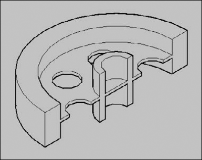
The SECTIONPLANE command creates a movable section object that displays the inside of a 3D model. When you turn live sectioning on, you can see the resulting cross-section in real-time as you move the section plane. You can flip the section plane to show the other half of the model. Figure 24.38 shows a section object.
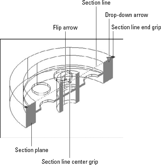
To create a section plane, follow these steps:

At the
Select face or any point to locate section line or [Draw section/Orthographic]:prompt, do one of the following:Pick a face of a 3D solid. Live sectioning is turned on.
Pick the first point of a section line. Then specify a second point at the
Specify through point:prompt.Use the Draw Section option to pick several points to create a section with corners (jogs). Live sectioning is turned off.
Use the Orthographic option to choose one of the orthographic directions. This creates a plane that applies to all 3D objects in your drawing. Live sectioning is turned on.
If Live sectioning is not on, you see just the section object's line. Select the section line, right-click, and choose Activate Live Sectioning.
Use the centerline end and center grips to move the section plane and adjust the sectioning of the object in real-time. You can use the flip arrow to view the other side of the object. Click the drop-down arrow to display a section boundary or section volume.
You can click the live section line and right-click to access section settings. To continue working, deactivate live sectioning and deselect the section plane line, which is quite unobtrusive.
The down arrow lets you choose a section boundary or volume. The section boundary defines a plane perpendicular to the section option, underlying the visible part of the 3D model. The section volume defines a box encompassing the visible part of the model.
To specify settings for section planes, click the dialog box launcher arrow at the right end of the Section panel's title bar to open the Section Settings dialog box. Here you can activate live sectioning and specify how the intersection of the object and the section looks.
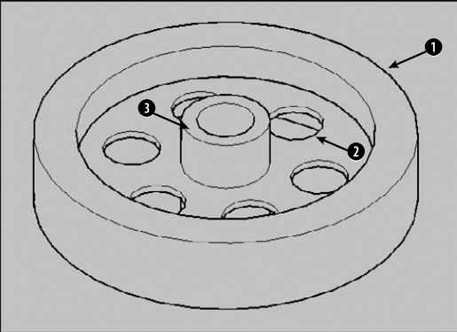
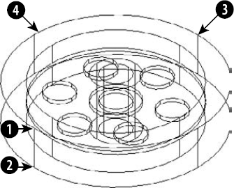
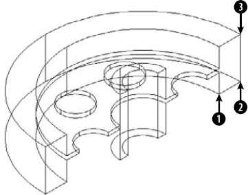
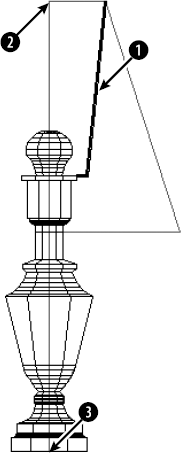
The SLICE command slices a solid (but not a mesh) into two parts along a plane or surface. The original solids are modified but can be reunited with UNION. You can delete either part or keep both. Figure 24.39 shows the result of slicing a model, after one half of the model has been deleted. This can help you to identify problems in the construction of the model. For example, this slice reveals a fault with the model — the flat disk continues through the central tube — not the desired result. However, you can also use the SLICE command to construct your models. For example, in the exercise on drawing basic solids, the lamp top was a sphere. You could slice this sphere, because the lamp should only have a top half of the sphere.
The Surface option enables you to cut any lofted, extruded, swept, or revolved surface out of the solid. You can create some interesting shapes this way.
Note
The drawing used in the following exercise on slicing solids, ab24-07.dwg, is in the Results folder on the DVD.
STEPS: Slicing Solids
If you did the exercise on creating complex solids, open
ab24-07.dwgfrom yourAutoCAD Biblefolder; otherwise, open it from theResultsfolder of the DVD. If necessary, change the visual style to 3D Wireframe. Object Snap should be on, with running object snaps for Endpoint, Midpoint, Center, and Quadrant. The drawing is shown in Figure 24.40.Save your drawing as
ab24-09.dwgin yourAutoCAD Biblefolder.
Select objects:
Select the solid model. Select objects:Right-click. Specify start point of slicing plane or [planar Object/Surface/Zaxis/View/XY/YZ/ZX/3points] <3points>:Specify first point on plane:Pick the quadrant atin Figure 24.40. Specify second point on plane:Pick the quadrant at. Specify third point on plane:Pick the quadrant at. Specify a point on desired side of the plane or [keep Both sides]:Pick the model at.As mentioned earlier, the slicing reveals an error — the disk cuts through the central tube, as shown in Figure 24.41. To fix the error, zoom in so that the model takes up the entire screen.
Start the CYLINDER command. Follow the prompts:
Specify center point of base or [3P/2P/Ttr/Elliptical]:
Pick the midpoint atin Figure 24.41. Specify base radius or [Diameter] <3.2605>:Pick the endpoint at. Specify height or [2Point/Axis endpoint] <9.2711>: Move the cursor upward and enter16.Choose Home tab
Change the visual style to 3D Hidden (choose Home tab
Save your drawing. If you're continuing on to the next exercise, keep the drawing open.
Note
To correct the model, you could subtract out the circle as you just did in the exercise, mirror the entire model, and use UNION to make the two halves whole. Mirroring in 3D is covered in the next section. You could also undo the slice as soon as you saw the error and make the correction on the entire model.
When you draw in 3D, you need to edit your models either to make corrections or as part of the construction process. A number of editing commands are exclusively for 3D or have special 3D options. In this section, you explore these special commands and options. Table 24.2 lists most of the 2D editing commands and how they're used in 3D drawings.
Table 24.2. Editing Commands in 3D
If the mirror line is on the XY plane, you can mirror any 3D object with the regular MIRROR command. If you want to mirror in any other plane, use MIRROR3D.
To use MIRROR3D, follow these steps:

Select the object or objects that you want to mirror.
At the
Specify first point of mirror plane (3 points) or [Object/Last/Zaxis/View/XY/YZ/ZX/3points] <3points>:prompt, choose one of the options to define the mirroring plane. These are the same options described in Table 24.1 for the SECTION command. The only additional option is Last, which uses the last defined mirroring plane.At the
Delete source objects? [Yes/No] <N>:prompt, press Enter to keep the original objects, or right-click and choose Yes to delete them.
Note
The drawing used in the following exercise on mirroring in 3D, ab24-09.dwg, is in the Results folder on the DVD.
STEPS: Mirroring in 3D
If you have
ab24-09.dwgopen from the previous exercise, use this drawing. If you don't have it open, open it from yourAutoCAD Biblefolder or from theResultsfolder of the DVD. If necessary, change the visual style to 3D Wireframe. Make sure that Object Snap is on, and set a running object snap for Endpoint. The drawing is shown in Figure 24.42.Save your drawing as
ab24-10.dwgin yourAutoCAD Biblefolder.
Select objects:
Select the solid. Right-click to end object selection. Specify first point of mirror plane (3 points) or [Object/Last/Zaxis/View/XY/YZ/ZX/3points] <3points>:Pickin Figure 24.42. Specify second point on mirror plane:Pick. Specify third point on mirror plane:Pick. Delete source objects? [Yes/No] <N>:Right-click and choose Enter.Choose Home tab
Save your drawing.
You can array any 3D object by using the ARRAY command as long as you define the array in the current XY plane. The 3DARRAY command enables you to create a rectangular array with the normal rows and columns, but adding levels in the Z direction. For a 3D polar array, you define an axis of rotation instead of the 2D point used in the ARRAY command.
A 3D rectangular array has rows, columns, and levels. To create a 3D rectangular array, follow these steps:

Select the objects that you want to array.
At the
Enter the type of array [Rectangular/Polar] <R>:prompt, right-click and choose Rectangular.At the
Enter the number of rows (---) <1>:prompt, type the total number of rows that you want. Rows are parallel to the X axis.At the
Enter the number of columns (|||) <1>:prompt, type the total number of columns that you want. Columns are parallel to the Y axis.At the
Enter the number of levels (...) <1>:prompt, type the total number of levels that you want. Levels are parallel to the Z axis.At the
Specify the distance between rows (---):prompt, type a unit distance or pick two points.At the
Specify the distance between columns (|||):prompt, type a unit distance or pick two points.At the
Specify the distance between levels (...):prompt, type a unit distance or pick two points.
Note
The drawing used in the following exercise on creating a rectangular array in 3D, ab24-i.dwg, is in the Drawings folder on the DVD.
STEPS: Creating a Rectangular Array in 3D
Open
ab24-h.dwgfrom the DVD.Save the file as
ab24-11.dwgin yourAutoCAD Biblefolder. This is a drawing showing a sphere, a bead-like shape sometimes used for table legs. In this exercise, you create a 3D rectangular array to create four table legs.
Select objects:
Select the bead. Right-click to end object selection. Enter the type of array [Rectangular/Polar] <R>:Right-click and choose Rectangular. Enter the number of rows (---) <1>:2Enter the number of columns (|||) <1>:2Enter the number of levels (...) <1>:20(The bead is 1.5 inches high and the leg should be 30 inches high.)Specify the distance between rows (---):26(This is the narrower distance between the legs.)Specify the distance between columns (|||):
36(This is the wider distance between the legs.)Specify the distance between levels (...):1.5(You want the beads to touch along the leg.)Do a Zoom Extents to see the result. (Now you would create the tabletop.)
Save your drawing. It should look like Figure 24.43.
Instead of using a center point as you do in a 2D polar array, you define a center axis. To create a 3D polar array, follow these steps:

Select the objects that you want to array.
At the
Enter the type of array [Rectangular/Polar] <R>:prompt, right-click and choose Polar.At the
Enter the number of items in the array:prompt, type the total number of items that you want.At the
Specify the angle to fill (+=ccw, −=cw) <360>:prompt, press Enter to array around a full circle or type any lesser angle.At the
Rotate arrayed objects? [Yes/No] <Y>:prompt, press Enter to accept the default or type nAt the
Specify center point of array:prompt, specify the center point of the array. This is also the first point of the axis of rotation.At the
Specify second point on axis of rotation:prompt, specify any other point on the axis of rotation.
If you rotate less than a full circle, you need to determine the positive angle of rotation. The positive direction of the axis goes from the first point that you specify (the center point) to the second point. Point your right thumb in the positive direction and follow the curl of the fingers of that hand to determine the positive angle of rotation.
Note
The drawing used in the following exercise on creating 3D polar arrays, ab24-i.dwg, is in the Drawings folder on the DVD.
STEPS: Creating 3D Polar Arrays
Open
ab24-i.dwgfrom the DVD.Save the file as
ab24-12.dwgin yourAutoCAD Biblefolder. You see part of a lamp, as shown in Figure 24.44. Make sure that Object Snap is on. Set a running object snap for Endpoint.
Select objects:
Select the support atin Figure 24.44. Select objects:Right-click. Enter the type of array [Rectangular/Polar] <R>:Right-click and choose Polar. Enter the number of items in the array:3Specify the angle to fill (+=ccw, -=cw) <360>:Rotate arrayed objects? [Yes/No] <Y>:Specify center point of array:Pick the endpoint at. Specify second point on axis of rotation:Pick the endpoint at.One of the three supports cannot be seen in this view. To see all three, press Shift+mouse wheel to enter transparent 3D Orbit mode, and drag diagonally a bit until you can see all three supports.
Choose Home tab
You can rotate 3D objects in the XY plane with the ROTATE command. Use ROTATE3D when you need to rotate objects in any other plane. (The 3DROTATE command, which I discuss later in this section, offers interactive rotating in 3D.) When you use the ROTATE3D command, you need to specify the axis of rotation. The ROTATE3D options are shown in Table 24.3.
Table 24.3. ROTATE3D Options
Option | Description |
|---|---|
Object | Enables you to choose a line, circle, arc, or 2D polyline. If you choose a circle or arc, AutoCAD rotates around a line that starts at the object's center and extends perpendicular to the object's plane. |
Last | Uses the last defined axis of rotation. |
View | Defines the axis of rotation parallel to the current view at the intersection of a point that you specify. |
Xaxis | The axis of rotation is parallel to the X axis and passes through a point that you specify. |
Yaxis | The axis of rotation is parallel to the Y axis and passes through a point that you specify. |
Zaxis | The axis of rotation is parallel to the Z axis and passes through a point that you specify. |
2points | This is the default. Specify two points to define the axis. It's a good idea to use object snaps. |
Tip
Sometimes creating an object in the XY plane and then rotating it afterward is easier. In other words, you may create an object in the wrong plane on purpose and use ROTATE3D or 3DROTATE later to properly place it.
To use ROTATE3D, follow these steps:
Enter rotate3d
Select the object or objects that you want to rotate.
At the
Specify first point on axis or define axis by [Object/Last/View/Xaxis/Yaxis/Zaxis/2points]:prompt, select one of the options explained in Table 24.3, and define the axis according to the option prompts.At the
Specify rotation angle or [Reference]:prompt, specify a positive or negative rotation angle or choose the Reference option. (The Reference option works like the Reference option for ROTATE. See Chapter 9.)
You need to determine the positive direction of rotation. Point your right thumb in the positive direction of the axis and follow the curl of your fingers. If you pick two points, the positive direction of the axis goes from the first pick point to the second pick point.
The 3DROTATE command and Rotate gizmo are covered earlier in this chapter.
Note
The drawing used in the following exercise on rotating in 3D, ab24-j.dwg, is in the Drawings folder on the DVD.
STEPS: Rotating in 3D
Open
ab24-j.dwgfrom the DVD.Save the file as
ab24-13.dwgin yourAutoCAD Biblefolder. You see the same lamp used in the previous exercise, but it has now been completed.To insert the lamp in a plan view drawing of a house, you need to see it in plan view from the WCS. In other words, you should be looking down at the lamp. To do this, you need to rotate the lamp around the X axis. To visualize this, look at the UCS icon and imagine rotating the top of the lamp toward you around the horizontal (X) axis. To rotate the lamp, enter rotate3d
Select objects:
Start a crossing window to select the entire lamp. Select objects:Right-click to end selection. Specify first point on axis or define axis by [Object/Last/View/Xaxis/Yaxis/Zaxis/2points]:Right-click and choose Xaxis. Specify a point on the X axis <0,0,0>:Right-click. Specify rotation angle or [Reference]:90Zoom to the extents of the drawing to see the entire lamp. The lamp is now rotated 90 degrees around the X axis in relation to the UCS, and you're looking at it from the top.
To get a better view, choose Home tab
Save your drawing.
To try the same rotation by using the 3DROTATE command, re-open
ab24-j.dwg. You can save it again asab24-13.dwg, because the result will be the same, or save it asab24-13-1.dwg.Press Shift+mouse wheel and change the viewpoint so that you can see all three axes on the UCS icon.

At the
Specify base point:prompt, specify the bottom corner of the lamp, using an Endpoint object snap.At the
Pick a rotation axis:prompt, hover over the red (X axis) ribbon until it turns yellow, and click.At the
Specify angle start point or type an angle:prompt, enter 90Change the visual style to 3D Hidden. Save your drawing.
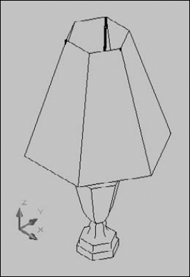
I have already covered the ALIGN and the 3DALIGN commands in Chapter 10. When you work in 3D, you can use these commands to move, rotate in the XY plane, and rotate in the Z direction — all in one command. In this exercise, you use the 3DALIGN command.
Note
The drawing used in the following exercise on aligning in 3D, ab24-k.dwg, is in the Drawings folder on the DVD.
STEPS: Aligning in 3D
Open
ab24-k.dwgfrom the DVD.Save the file as
ab24-14.dwgin yourAutoCAD Biblefolder. You see part of the base assembly for an industrial washer, as shown in Figure 24.46. One sidebar needs to be moved and rotated into place. Make sure that Object Snap is on; set a running object snap for Endpoint.Notice that it's hard to tell which way the sidebar is facing because it's displayed in wireframe. Change the visual style to 3D Hidden (choose Home tab

Select objects:
Select the sidebar. Select objects:Right-click. Specify base point or [Copy]:Pickin Figure 24.46. Specify second point or [Continue] <C>:Pick. Specify third point or [Continue] <C>:Pick. Specify first destination point:Pick. Specify second destination point or [eXit] <X>:Pick. Specify third destination point or [eXit] <X>: Pick any point further back thanon the plate.The smaller bars (shown in red in the drawing) provide several endpoints that you can easily locate.
AutoCAD aligns the sidebar. Save your drawing. It should look like Figure 24.47.
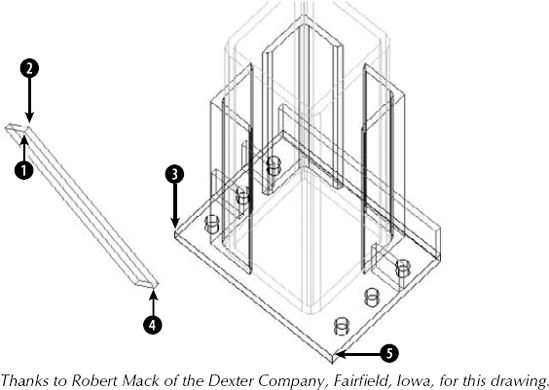
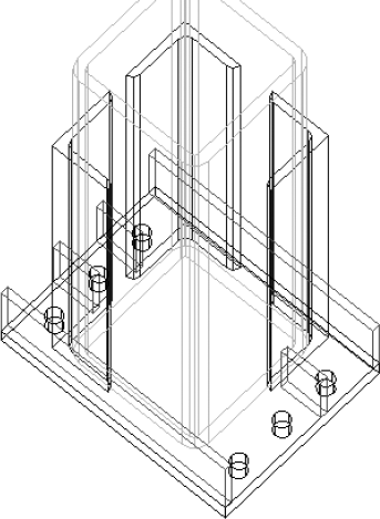
You can use the TRIM and EXTEND commands to trim or extend 2D objects in 3D space. (I cover these commands for 2D drawing in Chapter 10.) AutoCAD provides the Project option for working in 3D space. The Project option has three sub-options:
None. AutoCAD trims or extends only objects that actually intersect or can intersect in 3D space.
UCS. This is the default. AutoCAD projects objects onto the XY plane of the current UCS. Therefore, if two lines are on different Z coordinates, you can trim and extend one of them with reference to the other, even though they do not and cannot actually meet in 3D space.
View. This projects objects parallel to the current view. Objects are trimmed or extended, based on the way they look on the screen. They need not (and probably won't) actually meet in 3D space.
You can also use the Extend option to trim or extend to implied intersections, as explained in Chapter 10. In the next exercise, you practice extending objects in 3D; trimming works similarly.
Note
The drawing used in the following exercise on extending objects in 3D, ab24-l.dwg, is in the Drawings folder on the DVD.
STEPS: Extending Objects in 3D
Open
ab24-l.dwgfrom the DVD.Save the file as
ab24-15.dwgin yourAutoCAD Biblefolder. You see a bushing, in 2D and 3D, as shown in Figure 24.48. The 3D bushing has been exploded into simple geometry — otherwise, you wouldn't be able to use it to extend the 2D lines. Set the Quadrant running object snap.To turn the UCSORTHO system variable off, type ucsortho

Select boundary edges ... Select objects or <select all>:
Pick the 3D bushing atin Figure 24.48. Select objects:Right-click. Select object to extend or shift-select to trim or [Fence/Crossing/Project/Edge/Undo]:Right-click and choose Project. Enter a projection option [None/Ucs/View] <Ucs>:Right-click and choose View. Select object to extend or shift-select to trim or [Fence/Crossing/Project/Edge/Undo]:Pick the 2D bushing at. Select object to extend or shift-select to trim or [Fence/Crossing/Project/Edge/Undo]:Right-click and choose Enter.If you have difficulty extending, change the visual style to 2D Wireframe.
Choose Home tab
Choose View tab
Repeat the EXTEND command. Follow the prompts:
Select boundary edges...Select objects or <select all>:
Pick the bottom edge of the 3D bushing at. Select objects:Right-click. Select object to extend or shift-select to trim or [Fence/Crossing/Project/Edge/Undo]:Right-click and choose Project. Enter a projection option [None/Ucs/View] <View>:Right-click and choose None. Select object to extend or shift-select to trim or [Fence/Crossing/Project/Edge/Undo]:Pick the same line that you picked in Step 4, but this time pick it closer to the 3D bushing, on the new length you created by extending it. Select object to extend or shift-select to trim or [Fence/Crossing/Project/Edge/Undo]:Right-click and choose Enter.Choose Home tab
Click Undo on the Quick Access toolbar twice to undo the viewpoint change and the extend operation.
Choose Home tab
Start the EXTEND command again. Follow the prompts:
Select boundary edges... Select objects or <select all>:
Pick the 3D bushing at(the bottom ring). Select objects:Right-click. Select object to extend or shift-select to trim or [Fence/Crossing/Project/Edge/Undo]:Right-click and choose Project. Enter a projection option [None/Ucs/View] <View>:Right-click and choose Ucs. Select object to extend or shift-select to trim or [Fence/Crossing/Project/Edge/Undo]:Pick the same line that you extended before, closer to its left endpoint. Select object to extend or shift-select to trim or [Fence/Crossing/Project/Edge/Undo]:Right-click and choose Enter.Choose Home tab
Choose Home tab
Type ucsortho
Save your drawing. It should look like Figure 24.49.
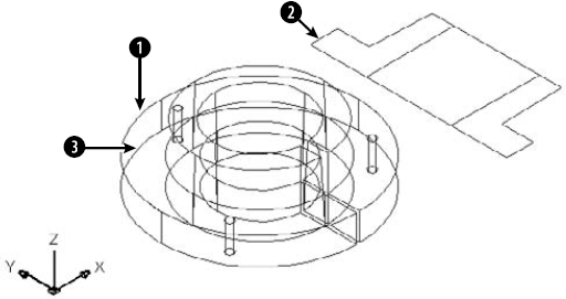
You can fillet solids but not meshes or surfaces. If you create a 3D object from lines, you can fillet the lines.
To use the FILLET command for solids, follow these steps:

At the
Select first object or [Undo/Polyline/Radius/Trim/Multiple]:prompt, select the edge of the solid that you want to fillet. You cannot deselect this edge, so you must select the solid at the proper edge. Ignore the other options.AutoCAD senses that you've selected a solid and responds with the
Enter fillet radius <0.5000>:prompt. Press Enter to accept the default of 0.5 or type a new radius.At the
Select an edge or [Chain/Radius]:prompt, press Enter if you want to fillet only the one edge that you've already selected. You can also select other edges of the same solid. Press Enter to end selection of edges. AutoCAD fillets the edge or edges that you selected. You can also change the Radius setting at this prompt.Use the Chain option to fillet a set of attached edges. AutoCAD responds with the
Select an edge chain or [Edge/Radius]:prompt. Continue to pick edges that are attached to the previous edge that you picked. Press Enter to end selection of edges. AutoCAD fillets the entire chain of edges.You can select different radii for different edges. At the first
Enter fillet radius <0.5000>:prompt, specify the radius for the edge you just selected. After that, use the Radius option to set the desired radius before you select the edge.
Note
The drawing used in the following exercise on filleting solids, ab24-m.dwg, is in the Drawings folder on the DVD.
STEPS: Filleting Solids
Open
ab24-m.dwgfrom the DVD.Save the file as
ab24-16.dwgin yourAutoCAD Biblefolder. This is a solid model of a mounting angle, as shown in Figure 24.50. It needs to be filleted. Turn Object Snap off.
At the
Select first object or [Undo/Polyline/Radius/Trim/Multiple]:prompt, pick the edge atAt the
Enter fillet radius <0.5000>:prompt, type .25At the
Select an edge or [Chain/Radius]:prompt, pickAt the
Select an edge or [Chain/Radius]:prompt, pickSave your drawing. It should look like Figure 24.51.
You can chamfer solids, but not meshes or surfaces. If you create a 3D object from lines, you can chamfer the lines.
To chamfer a solid, follow these steps:

At the
Select first line or [Undo/Polyline/Distance/Angle/Trim/mEthod/Multiple]:prompt, select the edge that you want to chamfer. The edge is displayed as a line between two surfaces. AutoCAD highlights one of the surfaces that touch the edge you selected.At the
Base surface selection...Enter surface selection option [Next/OK (current)] <OK>:prompt, press Enter to accept the highlighted surface as the base surface. You need to define the base surface in case the two chamfering distances are not equal or if you want to chamfer a loop, which is the entire base surface. Right-click and choose Next to highlight the next surface. (Only two surfaces touch the edge that you selected.) Press Enter when the desired surface is highlighted.At the
Specify base surface chamfer distance <0.5000>:prompt, type the chamfering distance for the first surface. This is the amount that you want to cut off from that surface. (The default is the last distance you specified.)At the
Specify other surface chamfer distance <0.5000>:prompt, type the chamfering distance for the other surface. (The default is the last distance you specified.)At the
Select an edge or [Loop]:prompt, select the edge that you want to chamfer. You can also use the Loop option. AutoCAD then prompts you to select the edge loop. Select the surface, and AutoCAD chamfers all the edges of that surface.AutoCAD continues to prompt you to select edges or edge loops. Press Enter to end selection when you're finished.
Note
The drawing used in the following exercise on chamfering solids, ab24-n.dwg, is in the Drawings folder on the DVD.
STEPS: Chamfering Solids
Open
ab24-n.dwgfrom the DVD.Save the file as
ab24-17.dwgin yourAutoCAD Biblefolder. This is a simple box with dimensions of 233 × 102 × 12 millimeters, as shown in Figure 24.52.
Select first line or [Undo/Polyline/Distance/Angle/Trim/mEthod/Multiple]:
Pick the edge atin Figure 24.52. Base surface selection... Enter surface selection option [Next/OK (current)] <OK>:Specify base surface chamfer distance <0.5000>:30Specify other surface chamfer distance <0.5000>:
30Select an edge or [Loop]:Pick. Select an edge or [Loop]:You can't see the chamfer because of the viewpoint. You change the viewpoint at the end of the exercise.
Repeat the CHAMFER command. Do the exact same operation as in Step 3, but pick
Repeat the CHAMFER command. Follow the prompts:
Select first line or [Undo/Polyline/Distance/Angle/Trim/mEthod/Multiple]:
Pick the edge at. Base surface selection... Enter surface selection option [Next/OK (current)] <OK>:Make sure that the surface indicated byis highlighted. If not, typen.Then press Enter again. Specify base surface chamfer distance <30.0000>:233Specify other surface chamfer distance <30.0000>:40Select an edge or [Loop]:Pick. Select an edge or [Loop]:Choose Home tab
Save your drawing. It should look like Figure 24.53.
The EXPLODE command has a particular effect that varies according to the type of 3D object. Table 24.4 lists the effects of exploding 3D objects.
Table 24.4. Using EXPLODE on 3D Objects
The Express Tools' FLATTEN command converts a 3D drawing into a 2D drawing, and changes the thickness and elevation of objects to zero. Choose Express Tools
The SOLIDEDIT command offers options to edit faces, edges, and complete smooth solids in specific ways. This command has so many options that it might as well be several commands. Many of the options are now out of date because of the methods of direct manipulation of solids introduced in AutoCAD 2007. However, the command still has value because it offers some options that are available nowhere else, or it makes certain edits easier. SOLIDEDIT doesn't work on meshes.
SOLIDEDIT offers three major types of solid editing:
Faces. A number of options enable you to edit the faces of solids. You can extrude, move, rotate, offset, taper, delete, copy, and color (assign a color to) faces.
Edges. You can color and copy edges.
Bodies. The body options apply to solids as a whole. You can imprint, separate, shell, clean, and check solids.
The next three sections explain how to edit faces, edges, and bodies.
A face is a surface on a solid. A face can be either flat or curved. For example, a hole in a block is a face, and many of the face-editing operations work well to modify holes. Of course, you can edit an outer face of a surface as well. The SOLIDEDIT command supports several methods of selecting a face or faces:
You can select sub-objects by using the Ctrl key, as described earlier in this chapter.
You can click within the boundary of a face. AutoCAD selects the front-most face.
You can click an edge to select its adjoining faces.
To make selecting the sub-object you want easier, choose Home tab
You may want to perform more than one operation on a face. After you complete an operation, you can right-click to open the shortcut menu and choose another operation. To exit the command, right-click and choose Exit twice or press Enter twice.
Extruding a face is like extruding a 2D object. Instead, you can select a face (as described earlier in this chapter) and use the EXTRUDE command; the prompts are similar. If you just want to extrude a face, without tapering it, you can grip-edit the solid.
AutoCAD extrudes the face. As you exit, AutoCAD performs a validation of the solid to make sure that the solid is a valid solid if the SOLIDCHECK system variable is on. By default, SOLIDCHECK is on (set to 1) and automatically checks solids when you edit them.
You can move a face when a solid is complex enough to have at least two separate elements — for example, a plate with a hole in it. You can then move the hole around wherever you want. You can also subselect the hole and move it by using its grips or the Move gizmo.
If you choose a face that cannot be moved, AutoCAD displays the Modeling Operation Error: No solution for an edge message.
You can offset a face when a solid has two separate elements, such as a wall with a window cut out of it. You can then resize the window by offsetting it. Offsetting a face increases all parts of the face equally by a distance that you specify.
Use a positive offset value to increase the volume of the solid. If your face is a solid axle in the middle of a disk, for example, and you offset the axle with a positive value, the axle gets bigger. However, if your face is a hole in the middle of a disk, a positive offset value makes the hole smaller because that makes the resulting solid bigger.
Use a negative offset value to decrease the volume of the solid. Using the same example, a negative offset value would make the axle smaller, but it would make the hole bigger.
To offset a face, follow these steps:

Select the face or faces that you want to offset and press Enter to end face selection.
At the
Specify the offset distance:prompt, type a positive or negative distance. You can also pick two points to specify a positive offset.Press Enter twice to exit the command.
AutoCAD offsets the face. If there is no room for the offset, AutoCAD displays the message Modeling Operation Error on the command line.
You can delete a face of a solid. This is a great way to instantly get rid of a hole, axle, or window within a solid. You can delete faces to undo the effects of both the UNION and SUBTRACT commands. You can also remove filleted and chamfered faces. AutoCAD won't delete every face; for example, you can't turn a box into a tetrahedron by deleting the box's top face. Note that you can also subselect the face and press the Del key.
You can rotate a face when a solid is complex enough to have at least two separate elements — for example, a box with a hole in it. The prompts for rotating are very similar to those for ROTATE3D, covered earlier in this chapter; you can select a sub-object and use that command, or the Rotate gizmo. To rotate a face by using SOLIDEDIT, choose Home tab
If you choose a face that cannot be rotated, or if there isn't room on the solid for the rotation, AutoCAD lets you know with the message Modeling Operation Error on the command line. Note that you can also subselect the face and rotate it by using grip-editing.
You can taper an entire simple solid, such as a box, or you can taper a face that is an element within a complex solid, such as a hole or an extruded face. Tapering angles the sides of the face. To determine the direction of the taper, that is, which end gets tapered, you specify a base point and a second point. The base point side of the solid is not tapered, and AutoCAD tapers the face in the direction from the base point toward the second point. You also specify the angle of the taper. A positive taper angle tapers the face inward; a hole is tapered outward. A negative taper angle tapers the face outward; a hole is tapered inward. In general, you should use small tapering angles. If the face tapers to a point before it reaches its existing height, then AutoCAD cannot complete the taper.
To taper a face, follow these steps:

Select the face(s) that you want to taper. Press Enter to end face selection.
At the
Specify the base point:prompt, pick the base point for the taper direction. Object snaps are a good idea.At the
Specify another point along the axis of tapering:prompt, specify a second point to indicate the direction of the taper. Again, use an object snap.At the
Specify the taper angle:prompt, specify an angle between −90° and +90°.Press Enter twice to exit the command.
If AutoCAD can't taper the face, you see the message Modeling Operation Error on the command line.
You can copy any face, including a hole. AutoCAD creates regions or surfaces out of the face. However, if you copy a complex face, such as a hole that may consist of several regions, you can't turn it back into a solid again.
To copy a face, follow these steps:

Select the face(s) that you want to copy. Press Enter to end face selection.
At the
Specify a base point or displacement:prompt, specify a base point. Object snaps are helpful.At the
Specify a second point of displacement:prompt, specify a second point to indicate the direction and distance for the copy.Press Enter twice to exit the command.
You can assign a color to a face of an object. You might want to color a face to make it easier to see. The color overrides the color setting for the solid's layer.
Note
When an object is assigned more than one material, priority goes to attachment by object, then by color, and finally by layer. If you attach a material to a solid by layer, and then attach a material to one of its faces (that you have colored) by color, both the solid and the face display their materials. For more information, see Chapter 25.
To color a face, follow these steps:

Select the face or faces that you want to color. Press Enter to end face selection.
AutoCAD opens the Select Color dialog box. Choose a color and click OK.
Press Enter twice to exit the command.
You can assign a material to a face of an object. You would do this for the purpose of displaying the object with that material in your drawing, or for rendering. For more information on materials and how to add them to your drawing, see Chapter 25.
To add a material to a face, first add the material to the drawing (as I explain in Chapter 25). Then follow these steps:
Start the SOLIDEDIT command. Choose the Face option, then choose the Material option.
Select the face or faces that you want to use. Press Enter to end face selection.
At the
Enter new material name <ByLayer>:prompt, type the name of the material as it appears in the Materials palette.Press Enter twice to exit the command.
The two-dimensional place where two faces meet is an edge. You can perform only two editing operations on edges: You can copy them and color them.
Several of the SOLIDEDIT options apply to solids as a whole. The operations available are imprinting, cleaning, separating, shelling, and checking. These operations are discussed in the following sections.
You can imprint an arc, circle, line, 2D polyline or 3D polyline, ellipse, spline, region, or 3D solid on a solid. The object that you're imprinting must intersect a face on the solid. The shape made by the intersection of the object is left on the solid, as if you put ink on the edges of the object and stamped it on the solid. Figure 24.54 shows an example of imprinting.
To imprint a solid, follow these steps:
First create one of the stampable objects previously listed so that it intersects with a solid. If you draw in top view, check in an isometric view to make sure that the intersection is where you want it.

At the
Select a 3D solid or surface:prompt, select a solid. You can select only one.At the
Select an object to imprint:prompt, select the object that you want to imprint.At the
Delete the source object [Yes/No] <N>:prompt, type yAutoCAD repeats the
Select an object to imprint:prompt. You can continue the command in the same way or press Enter if you're done.Press Enter to exit the command.
AutoCAD imprints the solid. If you didn't delete the source object, you'll need to move it to see the result. You can subselect an imprint and delete it or edit it in any other way. You can also use an imprint to divide a face, and then use the PRESSPULL command to extrude or press that portion of the face.
After all the editing, you can end up with some pretty strange solids. Cleaning solids removes adjacent faces that share the same surface and other duplicate or unused edges, vertices, and geometry. Cleaning does not remove imprints.
You can separate a solid that is made up of nontouching sections. You would generally create such a solid from separate, nontouching solids, using the UNION command. The Separate option undoes the effect of the UNION command so that the solids become separate again.
If your solid sections are even just touching, you get one of the odder AutoCAD messages: The selected solid does not have multiple lumps.
When you shell a solid, you hollow out its inside, leaving a thin wall. Think of making a drinking glass from a truncated cone (or tapered cylinder) or a room from a solid box. To shell a solid, follow these steps:

Select a solid.
At the
Remove faces or [Undo/Add/ALL]:prompt, remove any face or faces that you don't want to shell. For example, if you're making a drinking glass from a truncated cone, you want to remove the larger circular face (the one you would drink out of) so that it will remain open. Otherwise, you end up with an enclosed solid that has a hollow interior. After you finish removing faces, press Enter. (The command line confirms1 face found, 1 removed, but there is no visual confirmation that AutoCAD has removed the correct face.)At the
Enter the shell offset distance:prompt, type the width of the wall that you want to create. A positive value creates a shell to the inside of the current solid. A negative value creates a shell to the outside of the current solid.Press Enter twice to shell the solid and exit the command.
Checking ensures that your solid is a valid 3D solid object so that you can edit it without getting ACIS failure error messages. This might be a useful feature to put into an AutoLISP or VBA program, to make sure that it doesn't fail because of invalid solids.
Note
The drawing used in the following exercise on editing solid bodies, ab24-o.dwg, is in the Drawings folder on the DVD.
STEPS: Editing Solid Bodies
Open
ab24-o.dwgfrom the DVD.Save the file as
ab24-18.dwgin yourAutoCAD Biblefolder. This is a simple solid box with an ellipse drawn on part of its top face.
Select a 3D solid or surface:
Select the box. Select an object to imprint:Select the ellipse. Delete the source object [Yes/No] <N>:ySelect an object to imprint:Right-click to complete the imprint and end the command.Choose Home tab

Select a 3D Solid:
Select the box. Remove faces or [Undo/Add/ALL]:Pick anywhere inside the top face. Remove faces or [Undo/Add/ALL]:Right-click and choose Enter. Enter the shell offset distance:.1Press Enter twice to exit the command.
Choose Home tab
Save your drawing. It should look like Figure 24.55.
The MASSPROP command provides information about regions and solids that is useful for engineering applications. The bounding box, for example, is an imaginary box that contains the solid. The calculations are based on the relationship of the solid to the UCS. If you rotate the solid or change the UCS, you get different results. For example, after running MASSPROP to find the center of gravity (centroid) and axes of your model, move the UCS to the centroid and then run MASSPROP again to identify the moments of inertia, as shown in Figure 24.56.
For 2D regions, the area moment of inertia that MASSPROP generates can be used to calculate bending and twisting stresses. You could generate a 2D region of a solid model by using the SECTION command and then use the UCS command with the OBJECT option to set the UCS coplanar to the region. The MASSPROP command would then report the area moment of inertia.
AutoCAD assumes a density of 1 for all solids. You can then apply material density multipliers on the values that get reported.
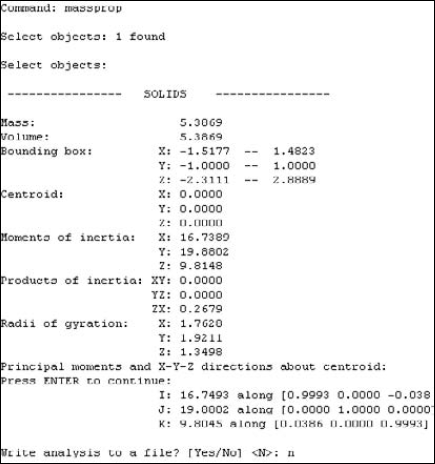
Note
You can use the MEASUREGEOM command to get the volume of a 3D model. Enter measuregeom
In this chapter, you learned how to create and edit solids. You read about:
Drawing basic shapes
Creating extruded, swept, revolved, and lofted solids from 2D profiles
Drawing polysolids
Manipulating solids by grip-editing, selecting sub-objects, and using the Move, Rotate, and Scale gizmos
Creating and editing mesh solids
Using UNION, SUBTRACT, and INTERSECT to create more-complex shapes
Using the INTERFERE command to see the volume of interference between solids
Pressing or pulling a solid
Utilizing the SECTION, SLICE, and SECTIONPLANE commands to visualize and reshape solids
Using the move grip tool and the 3DMOVE command
Using the special 3D editing commands MIRROR3D, 3DARRAY, and ROTATE3D
Using the 3DALIGN, TRIM, EXTEND, FILLET, and CHAMFER commands for 3D editing
Exploding into surfaces and solids into 2D objects
Using the SOLIDEDIT and IMPRINT command to edit faces, edges, and bodies
Calculating a number of engineering functions and values for solids by using the MASSPROP and MEASUREGEOM commands
In the next chapter, I cover rendering 3D models.