
In this chapter, you learn to create all types of surfaces, also called meshes. Specifically, they are polygonal meshes. Surfaces have a great advantage over 3D wireframe models because you can hide back surfaces and create shaded images for easier visualization of your models. Surfaces also enable you to create unusual shapes, such as topological maps or free-form objects.
You cannot obtain information about physical properties — such as mass, center of gravity, and so on — from surfaces. Such information can be obtained only from 3D solids, which are covered in the next chapter.
Note
This chapter assumes that you are using the 3D Modeling Workspace.
Note
This entire chapter applies to AutoCAD only. For information on surfaces that AutoCAD LT can create, see Chapter 21.
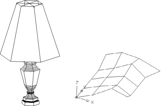
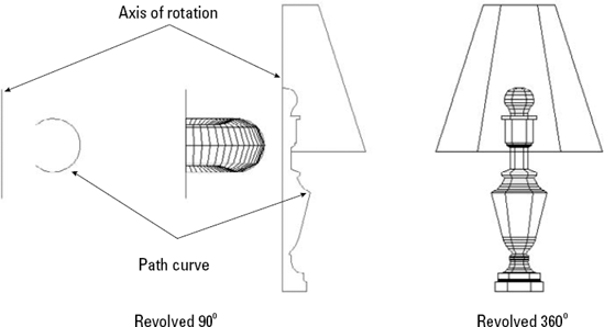
The left side of Figure 23.1 shows a lamp drawn with surfaces. The back edges are hidden, so the lamp looks somewhat realistic. AutoCAD approximates curved surfaces by creating a mesh of planes at varying angles. You see the planes because AutoCAD displays them using a web of intersecting lines. AutoCAD defines the mesh by its vertices — where the lines intersect. The right side of Figure 23.1 shows a mesh with its vertices.
Two-dimensional objects are often used to create three-dimensional models. In Chapter 21, I discuss how you can add a thickness to 2D solids (the SOLID command), wide polylines, and circles to make surfaces.
You can also use regions in 3D drawings. Although regions are 2D objects and cannot take a thickness, when you use the 3D Hidden visual style, AutoCAD displays the region as a surface. When you regenerate the drawing to a wireframe display, the region appears as a wireframe again, losing its surface properties.
Another option is to use 3DFACE, which is a true 3D command. 3DFACE creates three- or four-sided surfaces that can be in any plane. You can place surfaces together to make a many-sided surface. While AutoCAD draws lines between these surfaces, you can make the lines invisible to create the effect of a seamless surface. You define the surface by specifying the points that create the corners of the surface. As a result, a 3D face cannot have any curves. 3DFACE only creates surfaces — you cannot give a thickness to a 3D face. However, you can create a 3D solid from a 3D face by using the EXTRUDE command. 3D solids are covered in the next chapter.
To create a 3D face, type 3dface
Press Enter at the
Specify fourth point or [Invisible] <create three-sided face>:prompt to create a three-sided surface. Then press Enter again to end the command.Specify a fourth point to create a four-sided surface. AutoCAD repeats the
Specify third point or [Invisible] <exit>:prompt. Press Enter to end the command.Continue to specify points to create surfaces of more than four sides. AutoCAD repeats the third- and fourth-point prompts until you press Enter — twice after a third point or once after a fourth point. Note that each additional set of prompts creates a separate surface object.
As you continue to add faces, the last edge created by the third and fourth points becomes the first edge of the new face so that adding a face requires only two additional points.
Tip
It often helps to prepare for a complex 3D face by creating 2D objects for some or all of the faces. You can then use Endpoint object snaps to pick the points of the 3D face. Place these 2D objects on a unique layer. You can also use point objects with a visible point style as a basis for 3D faces.
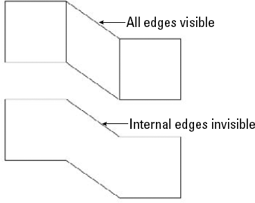
Making edges invisible makes a series of 3D faces look like one 3D face. Figure 23.2 shows three 3D faces with and without internal seams. You can control the visibility of 3D face edges in several ways.
While you're drawing the 3D face, you can right-click and choose Invisible before each edge. Then specify the next point. However, it's sometimes difficult to predict exactly where to indicate the invisible edge.
After creating the entire 3D face, you can use the EDGE command. The sole purpose of the EDGE command is to make 3D face edges visible and invisible — this is probably the easiest way to control the visibility of 3D face edges.
Type edge
To make invisible edges visible, choose the Display option. AutoCAD displays all the edges in dashed lines and shows the Enter selection method for display of hidden edges [Select/All] <All>: prompt. Press Enter to display all the edges or use the Select option to select 3D faces (you can use windows for selection). Either way, you see the edges of the 3D face that you want to edit. AutoCAD then repeats the Specify edge of 3dface to toggle visibility or [Display]: prompt. You can now select the edge that you want to make visible. Press Enter to end the command and make the edge visible.
Note
You may need to use the 2D Wireframe visual style to see the effect of making edges invisible. However, a plot gives the correct result.
Set the SPLFRAME system variable to 1, and then regenerate the drawing to make all 3D face edges visible. (The SPLFRAME system variable also affects the display of spline-fit polylines, hence its name.) To return edges to their original settings, set SPLFRAME to 0 and do a REGEN.
Note
The drawing used in the following exercise on drawing 3D faces, ab23-a.dwg, is in the Drawings folder on the DVD.
STEPS: Drawing 3D Faces
Open
ab23-a.dwgfrom the DVD.Save it as
ab23-01.dwgin yourAutoCAD Biblefolder. This is a blank drawing with architectural units, based onacad3D.dwt. The visual style is set to 3D Wireframe. Turn on Ortho Mode. Object Snap should be on. Set running object snaps for Endpoint and Midpoint. This exercise assumes that Dynamic Input is on and set to the default of relative coordinates.Type 3dface

Specify first point or [Invisible]:
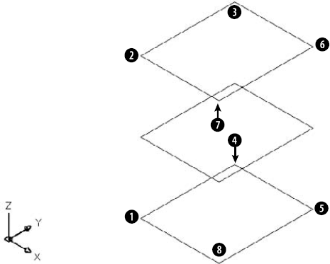
6,6Specify second point or [Invisible]:20,0Specify third point or [Invisible] <exit>:0,2'Specify fourth point or [Invisible] <create three-sided face>:ñ20,0Specify third point or [Invisible] <exit>:Start the COPY command. Follow the prompts:
Select objects:
Select the 3D face. Select objects:Specify base point or [Displacement/mOde] <Displacement>:Pick
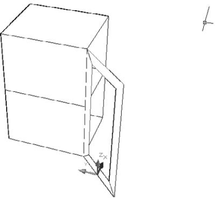
in Figure 23.3. Specify second point or <use first point as displacement>:0,0,1.5'Specify second point or [Exit/Undo]:0,0,3'Specify second point or [Exit/Undo]:If necessary, zoom and pan so that you can see all three surfaces. Your drawing should look like Figure 23.3. You now have the top, bottom, and middle shelves of the cabinet.
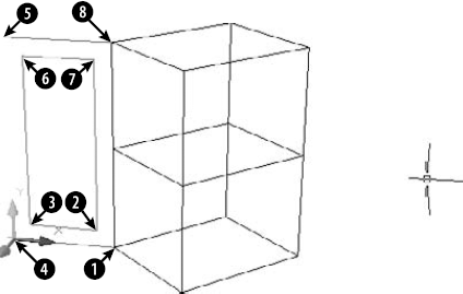
Start the 3DFACE command again. Follow the prompts:
Specify first point or [Invisible]:
Pick the endpoint atin Figure 23.3.Specify second point or [Invisible]:
Pick the endpoint at. Specify third point or [Invisible] <exit>:
Pick the endpoint at. Specify fourth point or [Invisible] <create three-sided face>:
Pickthe endpoint at. Specify third point or [Invisible] <exit>:
Pick the endpoint at. Specify fourth point or [Invisible] <create three-sided face>:
Pickthe endpoint at. Specify third point or [Invisible] <exit>:
Pick the endpoint at. Specify fourth point or [Invisible] <create three-sided face>:
Pickthe endpoint at. Specify third point or [Invisible] <exit>:
To draw the door of the cabinet, change the current layer to CONST. Start the LINE command and draw a line from
To make it easier to work on the door, choose View tab

Specify new origin point <0,0,0>:
Pick the left endpoint of thebottom construction line. Specify point on positive portion of X-axis <-0'-5 3/4″,-0'-6 3/4″,0′-0″>:Pickin Figure 23.3. Specify point on positive-Y portion of the UCS XY plane <-0'-7 7/16″,-0'-6″,0'-″>:Pick the left endpoint of the top constructionline.If the grid is on, you may want to turn it off.
Start the LINE command again. Follow the prompts:
Specify first point:
Choose the From object snap. Base point:Pick the left endpoint of the top construction line. <Offset>:@3,ñ3Specify next point or [Undo]:Move the cursor to the right and type12. Specify next point or [Undo]:Move the cursor down and type30. Specify next point or [Close/Undo]:Move the cursor to the left andtype12. Specify next point or [Close/Undo]:cYour drawing should look like Figure 23.4.
Change the current layer to 0. Start the 3DFACE command again. Follow the prompts:
Specify first point or [Invisible]:
Pick the endpoint atin Figure23.4. Specify second point or [Invisible]:Pick the endpoint at. Specify third point or [Invisible] <exit>:Pick the endpoint at. Specify fourth point or [Invisible] <create three-sided face>:Pickthe endpoint at. Notice the edge lines betweenandandbetweenand. Specify third point or [Invisible] <exit>:Right-click and chooseInvisible. Pick the endpoint at. Specify fourth point or [Invisible] <create three-sided face>:Pickthe endpoint at. Specify third point or [Invisible] <exit>:Right-click and chooseInvisible. Pick the endpoint at. Specify fourth point or [Invisible] <create three-sided face>:Pickthe endpoint at. Specify third point or [Invisible] <exit>:Pick the endpoint at. Specify fourth point or [Invisible] <create three-sided face>:Pickthe endpoint at. Specify third point or [Invisible] <exit>:Type edge
Choose View tab
Type ddvpoint
Choose Home tab
Save your drawing. It should look like Figure 23.5.
PFACE draws surfaces called polyface meshes, which are a type of polyline. However, you cannot edit them with PEDIT. The best way to edit them is with grips. AutoCAD designed PFACE for the creation of surfaces using AutoLISP routines or other automated methods. Consequently, the input for polyface meshes is somewhat awkward. However, polyface meshes have the following advantages:
You can draw surfaces with any number of sides, unlike 3D faces, which can have only three or four sides.
The entire surface is one object.
Sections that are on one plane do not show edges, so you don't have to bother with making edges invisible.
You can explode polyface meshes into 3D faces.
If you create a polyface mesh on more than one plane, each plane can be on a different layer or have a different color. This can be useful for assigning materials for rendering or other complex selection processes.
On the other hand, polyface meshes are difficult to create and edit. Figure 23.6 shows two polyface meshes, one on one plane and the other on three planes.
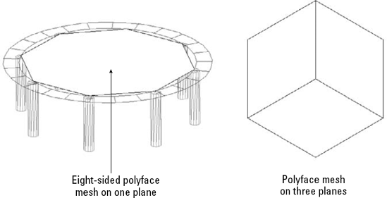
Figure 23.6. You can create many-sided polyface meshes on one plane, or on several different planes. After you switch to the 3D Hidden visual style, the polyface mesh hides objects behind it.
The prompts for PFACE are divided into two phases. The first phase simply asks for vertices. The second phase asks you to specify which vertex makes up which face (or plane). The second phase is fairly meaningless for polyface meshes on one plane, but you have to specify the vertices anyway. Here are the steps:
Type pface
At the
Specify location for vertex 1:prompt, specify the first vertex.Continue to specify vertices at the
Specify location for vertex 2 or <define faces>:orSpecify location for vertex 3 or <define faces>:prompt. Press Enter when you've finished.At the
Face 1, vertex 1: Enter a vertex number or [Color/Layer]:prompt, type which vertex starts the first face of the polyface mesh. It's usually vertex 1, so you type 1At the
Face 1, vertex 2: Enter a vertex number or [Color/Layer] <next face>:prompt, type which vertex comes next on the first face. Continue to specify the vertices for the first face.If you're drawing a polyface mesh on one plane, continue to specify all the vertices in order, and then press Enter twice when you're done, to end the command.
If you're drawing a polyface mesh on more than one plane, continue to specify the vertices on the first face (that is, plane) and press Enter. At the
Face 2, vertex 1: Enter a vertex number or [Color/Layer]:prompt, type the first vertex of the second face (plane) and continue to specify vertices for the second face. Press Enter. Continue to specify vertices for all the faces. Press Enter twice to end the command.
Tip
In order to easily draw a polyface mesh with PFACE, draw 2D or point objects as a guide for picking vertices. Then you can use object snaps to pick the vertices. Also, for polyface meshes on more than one plane, draw a diagram that numbers the vertices. This helps you to specify which vertices make up which face.
During the second phase of the prompts, when PFACE asks you to define the faces, you can right-click and choose Layer or Color and specify the layer or color. Then specify the vertices that are to be on that layer or color.
In the following exercise, you draw a hexagonal night table with polyface meshes.
Note
The drawing used in the following exercise on drawing polyface meshes, ab23-b.dwg, is in the Drawings folder on the DVD.
STEPS: Drawing Polyface Meshes
Open
ab23-b.dwgfrom the DVD.Save it as
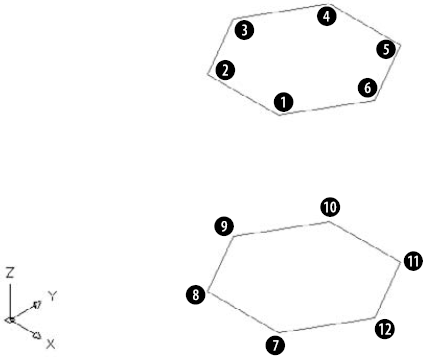
ab23-02.dwgin yourAutoCAD Biblefolder. Two hexagons have been drawn, one 24 inches above the other, on the Const layer, as shown in Figure 23.7.Type pface
Specify location for vertex 1:
Pickin Figure 23.7. Specify location for vertex 2 or <define faces>:Pick. Specify location for vertex 3 or <define faces>:Pick. Specify location for vertex 4 or <define faces>:Pick. Specify location for vertex 5 or <define faces>:Pick. Specify location for vertex 6 or <define faces>:Pick. Specify location for vertex 7 or <define faces>:Pick. Specify location for vertex 8 or <define faces>:Pick. Specify location for vertex 9 or <define faces>:Pick. Specify location for vertex 10 or <define faces>:
Pick. Specify location for vertex 11 or <define faces>:
Pick. Specify location for vertex 12 or <define faces>:
Pick. Specify location for vertex 13 or <define faces>: Face 1, vertex 1: Enter a vertex number or [Color/Layer]:
1Face 1, vertex 2: Enter a vertex number or [Color/Layer] <next face>:2Face 1, vertex 3: Enter a vertex number or [Color/Layer] <next face>:3Face 1, vertex 4: Enter a vertex number or [Color/Layer] <next face>:4Face 1, vertex 5: Enter a vertex number or [Color/Layer] <next face>:5Face 1, vertex 6: Enter a vertex number or [Color/Layer] <next face>:6Face 1, vertex 7: Enter a vertex number or [Color/Layer] <next face>:Face 2, vertex 1: Enter a vertex number or [Color/Layer]:12Face 2, vertex 2: Enter a vertex number or [Color/Layer] <next face>:6Face 2, vertex 3: Enter a vertex number or [Color/Layer] <next face>:5Face 2, vertex 4: Enter a vertex number or [Color/Layer] <next face>:11Face 2, vertex 5: Enter a vertex number or [Color/Layer] <next face>:Face 3, vertex 1: Enter a vertex number or [Color/Layer]:5Face 3, vertex 2: Enter a vertex number or [Color/Layer] <next face>:11Face 3, vertex 3: Enter a vertex number or [Color/Layer] <next face>:10Face 3, vertex 4: Enter a vertex number or [Color/Layer] <next face>:4Face 3, vertex 5: Enter a vertex number or [Color/Layer] <next face>:
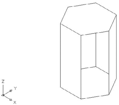
Face 4, vertex 1: Enter a vertex number or [Color/Layer]:10Face 4, vertex 2: Enter a vertex number or [Color/Layer] <next face>:4Face 4, vertex 3: Enter a vertex number or [Color/Layer] <next face>:3Face 4, vertex 4: Enter a vertex number or [Color/Layer] <next face>:9Face 4, vertex 5: Enter a vertex number or [Color/Layer] <next face>:Face 5, vertex 1: Enter a vertex number or [Color/Layer]:3Face 5, vertex 2: Enter a vertex number or [Color/Layer] <next face>:9Face 5, vertex 3: Enter a vertex number or [Color/Layer] <next face>:8Face 5, vertex 4: Enter a vertex number or [Color/Layer] <next face>:2Face 5, vertex 5: Enter a vertex number or [Color/Layer] <next face>:Face 6, vertex 1: Enter a vertex number or [Color/Layer]:8Face 6, vertex 2: Enter a vertex number or [Color/Layer] <next face>:2Face 6, vertex 3: Enter a vertex number or [Color/Layer] <next face>:1Face 6, vertex 4: Enter a vertex number or [Color/Layer] <next face>:7Face 6, vertex 5: Enter a vertex number or [Color/Layer] <next face>:Face 7, vertex 1: Enter a vertex number or [Color/Layer]:7Face 7, vertex 2: Enter a vertex number or [Color/Layer] <next face>:8Face 7, vertex 3: Enter a vertex number or [Color/Layer] <next face>:9Face 7, vertex 4: Enter a vertex number or [Color/Layer] <next face>:10Face 7, vertex 5: Enter a vertex number or [Color/Layer] <next face>:11Face 7, vertex 6: Enter a vertex number or [Color/Layer] <next face>:12Face 7, vertex 7: Enter a vertex number or [Color/Layer] <next face>:Face 8, vertex 1: Enter a vertex number or [Color/Layer]:Choose Home tab
Save your drawing. It should look like Figure 23.8.
The number of lines on the surface depends on the values of the SURFU and SURFV system variables. The default value for both is 6. You can use the Object option to turn closed 2D objects into a planar surface.
Note
You can now perform certain types of editing on nonmesh surfaces that previously were available only for solids. These editing operations include unions, subtractions, interferences, intersections, and imprinting, and they work on planar surfaces, as well as surfaces created with the REVOLVE, EXTRUDE, SWEEP, and LOFT commands. These last four commands are covered later in this chapter. I cover solids, mesh objects, and 3D editing in Chapter 24.
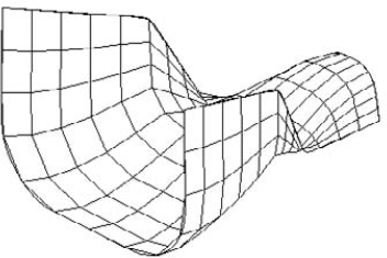
The 3DMESH command creates polygon meshes (not to be confused with the polyface meshes created by PFACE). The 3DMESH command is used for creating irregular surfaces, vertex by vertex. The advantage of polygon meshes is that AutoCAD considers them to be polylines, and you can therefore edit them with the PEDIT command — although in a limited manner. Figure 23.10 shows two surfaces created with 3DMESH. The surface on the right has been smoothed by using PEDIT.
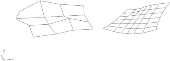
Figure 23.10. Two surfaces created with 3DMESH. The surface on the right has been smoothed, using the Smooth option of PEDIT.
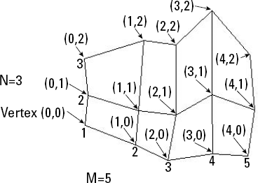
After you set the size of the 3D Mesh, you need to specify each vertex. For example, the 3D Mesh in Figure 23.11 has 15 vertices that you need to specify. AutoCAD prompts you for each vertex in order, starting with (0,0). Vertex (0,1) is the second vertex in the first column. Vertex (1,0) is the first vertex in the second column, starting from the bottom. It's a little confusing because AutoCAD starts the counting from 0 (zero), not 1. For the 3D Mesh in Figure 23.11, the last vertex is (4,2).
Note
In Figure 23.11, the 3D Mesh is five vertices wide and three vertices high as you look at it in plan view. However, you don't have to specify the vertices in the same direction. For the 3D Mesh in the figure, I started at the bottom left, continued to move up for (0,1) and (0,2), then moved to the right. However, you could start at the bottom left and move to the right for (0,1) and (0,2), and then go back to the left either above or below (0,0) — resulting in a 3D Mesh that is three vertices wide and five vertices high as you look at it in plan view. In other words, M and N can be in any direction.
3D meshes are especially suitable for AutoLISP routines; in fact, AutoCAD supplies several. I discuss these in the next section.
To smooth a polygon mesh, start the PEDIT command and select the polygon mesh. AutoCAD responds with the Enter an option [Edit vertex/Smooth surface/Desmooth/Mclose/Nclose/Undo]: prompt. Table 23.1 explains how to use these options.
Table 23.1. PEDIT options for 3D polygon meshes
Option | Description |
|---|---|
Edit vertex | Displays the |
Smooth surface | Smoothes the surface according to one of three possible sets of equations — Quadratic, Cubic, or Bézier. Bézier results in the smoothest surface. Use the SURFTYPE system variable to set the type of smoothing. Set SURFTYPE to 5 to create a quadratic b-spline surface, 6 to create a cubic b-spline surface, or 7 to create a Bézier surface. Cubic (6) is the default setting. To smooth a 3D Mesh, there must be more than three vertices in both the M and N directions. |
Desmooth | Removes the smoothing on the 3D Mesh surface. |
Mclose | Closes the surface in the M direction by connecting the last edge to the first edge. |
Nclose | Closes the surface in the N direction by connecting the last edge to the first edge. |
Undo | Undoes the last option. |
You can use 3DMESH to create 3D topological surfaces. You may have a surveyor's drawing that marks measurement points. Open a new drawing, using the surveyor's drawing as an xref. In plan view, create a polygon mesh. For the vertices, pick the surveyor's measurement points. (You'll need to count them first to determine a regular grid for the M and N sizes.) Then select the polygon mesh to display its grip points. Select each grip in turn, and at the prompt, type (for example) @0,0,100.78
AutoCAD includes several AutoLISP routines that use 3D meshes to create some standard shapes. These shapes are all options of the 3D command, which you enter on the command line. You can also type ai_ followed by the name of the shape, such as ai_box.
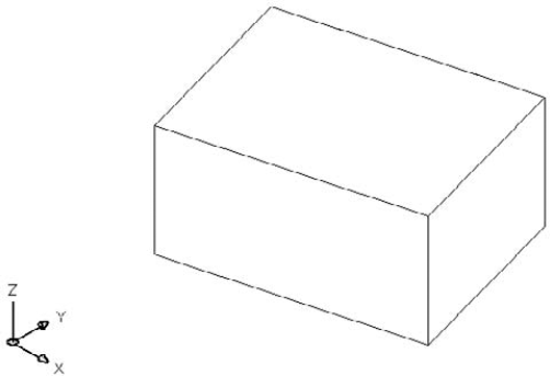
Figure 23.12 shows a surface mesh box from the SE isometric viewpoint in the 3D Hidden visual style.
Here's how to draw a box:
Enter 3d
At the
Specify corner point of box:prompt, specify the lower-left corner of the base of the box.At the
Specify length of box:prompt, specify the length of the box along the X axis. You can pick a point or enter a value.At the
Specify width of box or [Cube]:prompt, specify the width of the box along the Y axis. You can pick a point or enter a value. If you choose the Cube option, AutoCAD creates a cube with a width and height the same as the length that you just specified, and you don't see the height prompt.At the
Specify height of box:prompt, specify the height of the box along the Z axis. Pick a point or enter a value.At the
Specify rotation angle of box about the Z axis or [Reference]:prompt, specify an angle. AutoCAD rotates the box in the XY plane. Press Enter if you do not want to rotate the box. You can also use the Reference suboption, which works like the Reference option of the ROTATE command.
As you define the box, AutoCAD draws a temporary image in yellow to show you the result of your specifications.
Figure 23.13 shows a wedge. The prompts are the same as for the box, except that there is no Cube option. A wedge is a diagonal half of a box.
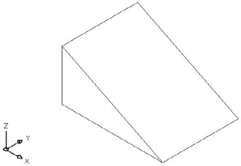
Here's how to draw a wedge:
Enter 3d
At the
Specify corner point of wedge:prompt, specify the lower-left corner of the base of the wedge.At the
Specify length of wedge:prompt, specify the length of the wedge along the X axis.At the
Specify width of wedge:prompt, specify the width of the wedge along the Y axis.At the
Specify height of wedge:prompt, specify the height of the wedge along the Z axis.At the
Specify rotation angle of wedge about the Z axis:prompt, specify an angle. AutoCAD rotates the wedge in the XY plane. Press Enter if you don't want to rotate the wedge.
You can draw pyramids with three- and four-sided bases. A pyramid with a three-sided base creates a four-sided object called a tetrahedron. You can top the pyramid with a point, a flat top, or, for four-sided bases, a ridge. Figure 23.14 shows the various types of pyramids that you can draw.
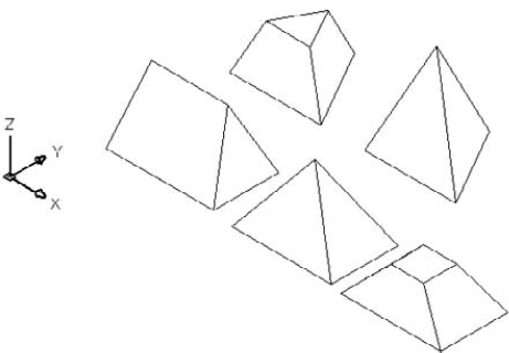
Here's how to draw the pyramids:
Enter 3d
At the
Specify first corner point for base of pyramid:prompt, specify the first point (any point) on the base.At the
Specify second corner point for base of pyramid:prompt, specify the second point on the base.At the
Specify third corner point for base of pyramid:prompt, specify the third point on the base.At the
Specify fourth corner point for base of pyramid or [Tetrahedron]:prompt, specify the fourth point on the base or choose the Tetrahedron option (creates a pyramid with a base of three points).If you chose the Tetrahedron option, at the
Specify apex point of tetrahedron or [Top]:prompt, specify the apex (top point) or choose the Top option. AutoCAD prompts you for three top points.If you specified a fourth base point, at the
Specify apex point of pyramid or [Ridge/Top]:prompt, specify the apex (top point) or choose the Ridge or Top option. If you choose the Ridge option, specify the two points for the ridge. If you choose the Top option, specify the four top points.
Specifying the apex or ridge can be tricky unless you know the absolute coordinates that you want. You can't change viewpoints during the command. However, you can easily change the points later by using grips. Another trick is to start any drawing command, such as LINE, before starting the pyramid. At the Specify first point: prompt, pick the point that you want to use for the first base point of the pyramid. Then press Esc to cancel the command. This leaves that point as the last point specified. Now define the base of the pyramid, using the same point as the first base point. When you need to specify the apex or ridge, you can use relative coordinates from the first base point. For example, to create an apex two units directly over the first base point, specify @0,0,2 for the apex.
When you use the Top option, AutoCAD provides a rubber-band line from each of the base corners in turn, letting you use relative coordinates from the base corners. You can also create a temporary 2D object before starting the pyramid to frame a ridge or top.
You can create full or partial cones. Figure 23.15 shows both types, as displayed in the 3D Wireframe visual style.
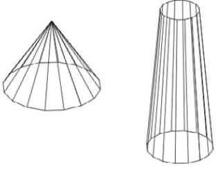
Follow these steps to create cones:
Enter 3d
At the
Specify center point for base of cone:prompt, pick the center for the circle that makes the base of the cone.At the
Specify radius for base of cone or [Diameter]:prompt, specify the radius for the circle at the base or choose the Diameter option to specify the diameter.At the
Specify radius for top of cone or [Diameter] <0>:prompt, specify the radius of the top or choose the Diameter option and specify the diameter. If you accept the default of zero, you get a complete cone. If you specify a radius or diameter, you get a truncated cone.Note
You can specify the base's size to be larger than the top's size.
At the
Specify height of cone:prompt, specify the height.At the
Enter number of segments for surface of cone <16>:prompt, specify the number of mesh segments. A higher number results in a smoother-looking cone.
Drawing a sphere is quite easy. You just specify the center and radius and then the number of segments to display in each direction. Figure 23.16 shows a sphere in the 3D Wireframe visual style.
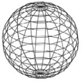
Here's how to draw a sphere:
Enter 3d
At the
Specify center point of sphere:prompt, specify a point.At the
Specify radius of sphere or [Diameter]:prompt, specify the radius, or choose the Diameter option to specify the diameter.At the
Enter number of longitudinal segments for surface of sphere <16>:prompt, type the number of north-south lines that you want. A higher number results in a smoother-looking sphere.At the
Enter number of latitudinal segments for surface of sphere <16>:prompt, type the number of east-west lines that you want. A higher number results in a smoother-looking sphere.
The only tricky issue with spheres is remembering that the center point is the center in all three dimensions. If you want to draw a ball on a table, it's easy to specify the center on the plane of the tabletop — but you end up with a ball that's half beneath the table. So plan ahead.
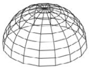
A dome is the top half of a sphere, as shown in Figure 23.17. The prompts are very similar to those for a sphere.
Follow these steps to draw a dome:
Enter 3d
At the
Specify center point of dome:prompt, specify the center point of the circle that makes up the base of the dome.At the
Specify radius of dome or [Diameter]:prompt, specify the radius or use the Diameter option to specify the diameter.At the
Enter number of longitudinal segments for surface of dome <16>:prompt, type the number of north-south lines that you want. A higher number results in a smoother-looking dome.At the
Enter number of latitudinal segments for surface of dome <8>:prompt, type the number of east-west lines that you want. A higher number results in a smoother-looking dome. Notice that the default is 8 instead of 16 for the sphere because you're drawing only half of a sphere.
A dish is the bottom half of a sphere, as shown in Figure 23.18. Actually, a bowl would be a better name for it.
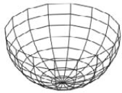
Follow these steps to draw a dish:
Enter 3d
At the
Specify center point of dish:prompt, specify the center point of the circle that makes up the base of the dish.At the
Specify radius of dish or [Diameter]:prompt, specify the radius or use the Diameter option to specify the diameter.At the
Enter number of longitudinal segments for surface of dish <16>:prompt, type the number of north-south lines that you want. A higher number results in a smoother-looking dish.At the
Enter number of latitudinal segments for surface of dish <8>:prompt, type the number of east-west lines that you want. A higher number results in a smoother-looking dish. As with the sphere, the default is 8 because you're drawing only half of a sphere.
As with spheres, remember that the center point is the center of the top of the dish, not its base.
A torus is a 3D donut, as shown in Figure 23.19.
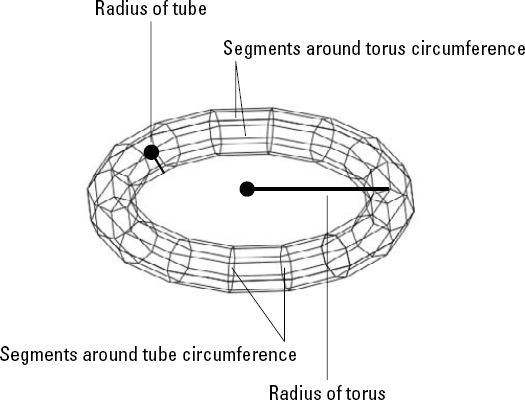
Follow these steps to create a torus:
Enter 3d
At the
Specify center point of torus:prompt, specify the center of the torus.At the
Specify radius of torus or [Diameter]:prompt, specify the radius of the torus, shown in Figure 23.19, or use the Diameter option to define the diameter.At the
Specify radius of tube or [Diameter]:prompt, specify the radius of the tube or use the Diameter option to define the diameter.At the
Enter number of segments around tube circumference <16>:prompt, specify the number of segments around the tube.At the
Enter number of segments around torus circumference <16>:prompt, specify the number of segments around the torus.
As with a sphere, a torus is half above and half below the center point in the Z direction.
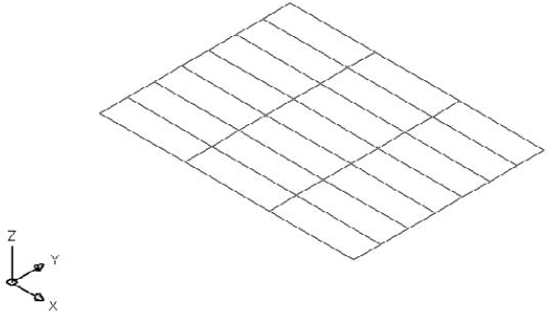
The 3D command has a Mesh option that creates a 3D Mesh. All you have to do is pick the four corners and the M and N mesh sizes. This is similar to a planar surface, except that you can choose the number of mesh lines during the command. Specify the four corner points in clockwise or counterclockwise order. Then specify the M and N mesh sizes. Figure 23.20 shows a mesh with M=8 and N=4.
Note
The drawing used in the following exercise on drawing 3D polygon meshes, ab23-c.dwg, is in the Drawings folder on the DVD.
STEPS: Drawing 3D Polygon Meshes
Open
ab23-c.dwgfrom the DVD.Save it as
ab23-03.dwgin yourAutoCAD Biblefolder. The drawing is in architectural units. Object Snap should be on. Set running object snaps for Endpoint and Midpoint.Enter 3d
Specify corner point of box:
1,1,30Specify length of box:4'Specify width of box or [Cube]:3'Specify height of box:1Specify rotation angle of box about the Z axis or [Reference]:Do a Zoom Extents to see the entire box.
Start the 3D command with the Box option again. Follow the prompts to make a leg:
Specify corner point of box:
1,1Specify length of box:1Specify width of box or [Cube]:1Specify height of box:30Specify rotation angle of box about the Z axis or [Reference]:0Mirror the leg, from one side of the table to the opposite side, using midpoint object snaps for the mirror line. Then mirror the two legs in the other direction, so that you have four legs. Zoom out and pan as necessary to center the table in the drawing area.
Note
If you have trouble finding the Midpoint object snaps, change the visual style to 2D Wireframe.
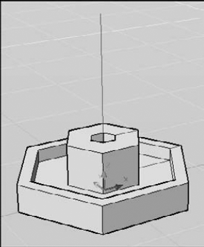
Start the 3D command with the Dish option. Follow the prompts to create a bowl on the table:
Specify center point of dish:
2',2',35-1/2Specify radius of dish or [Diameter]:dSpecify diameter of dish:9Enter number of longitudinal segments for surface of dish <16>:Enter number of latitudinal segments for surface of dish <8>:The dish's diameter is 9, so its height is half that, or 4½. The center of the dish is at height 35½ because the tabletop is at 31 (31 + 4½ = 35½).
Type elev
Start the 3D command with the Cone option. Follow the prompts to create a salt shaker:
Specify center point for base of cone:
2',1'6Specify radius for base of cone or [Diameter]:1Specify radius for top of cone or [Diameter] <0>:.5Specify height of cone:4Enter number of segments for surface of cone <16>:8Start the 3D command with the Sphere option. Follow the prompts to draw an orange in the bowl:
Specify center point of sphere:
2',2',32-1/2Specify radius of sphere or [Diameter]:dSpecify diameter of sphere:3Enter number of longitudinal segments for surface of sphere <16>:8Enter number of latitudinal segments for surface of sphere <16>:8Start the 3D command with the Cone option again. Follow the prompts to make a plate.
(It may not seem logical to use a cone to make a flat plate. However, it works because you can create a truncated cone that is upside down and very shallow. It's an unusual but interesting use for the CONE command.)
Specify center point for base of cone:
1',1'Specify radius for base of cone or [Diameter]:2Specify radius for top of cone or [Diameter] <0>:5Specify height of cone:1/2Enter number of segments for surface of cone <16>:Start the 3D command with the Wedge option. Follow the prompts to make a wedge of cheese on the plate:
Specify corner point of wedge:
10,10Specify length of wedge:5Specify width of wedge:2Specify height of wedge:2Specify rotation angle of wedge about the Z axis:30Start the 3D command with the Pyramid option. Follow the prompts to draw a pyramidal pepper shaker:
Specify first corner point for base of pyramid:
2'6,2'6Specify second corner point for base of pyramid:1,0Specify third corner point for base of pyramid:0,1Specify fourth corner point for base of pyramid or [Tetrahedron]:−1,0Specify apex point of pyramid or [Ridge/Top]:tSpecify first corner point for top of pyramid:1/4,1/4,3Specify second corner point for top of pyramid:−1/4,1/4,3Specify third corner point for top of pyramid:−1/4,−1/4,3Specify fourth corner point for top of pyramid:1/4,−1/4,3Choose Home tab
Save your drawing. It should look like Figure 23.21. If you look carefully, you'll see that the edge of the cheese wedge goes slightly through the plate.

A common way to define a surface is to revolve an outline around an axis. You can create some very complex surfaces in this way. AutoCAD offers two ways to create surfaces from the revolution of an outline.
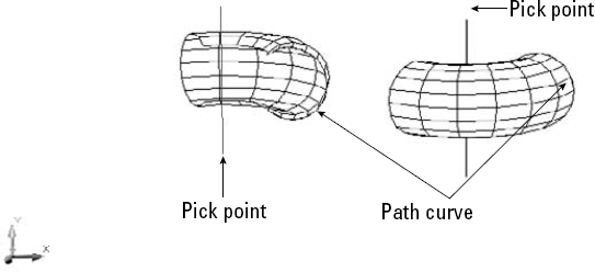
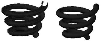
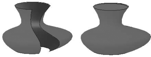
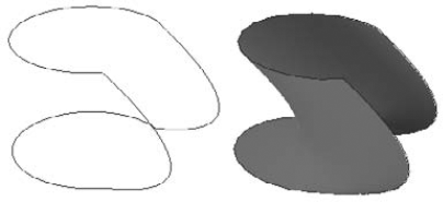
The REVSURF command takes an object that defines an outline or profile — AutoCAD also calls it a path curve — and revolves it around an axis, creating a 3D polygon mesh. Figure 23.22 shows two examples of revolved surfaces.
Note
The REVSURF command now creates a mesh object by default. You can create a polyface or polygon, or full-feature meshes by setting the MESHTYPE system variable's value to 0. Mesh objects are covered fully in Chapter 24.
The path curve must be one object — a line, arc, circle, polyline, ellipse, or elliptical arc. It can be open, like the path curves shown in Figure 23.22, or closed. A closed path curve creates a model that is closed in the N direction.
Tip
If you have several adjoining objects that you'd like to use as one path curve, remember that you can use PEDIT to change lines and arcs to polylines and join them together. For more information, see Chapter 16. You can also use the JOIN command, which I cover in Chapter 10.
You can start the angle of rotation at any angle; it doesn't have to start on the plane of the path curve. You can rotate the path curve to any angle. Of course, rotating the path curve 360 degrees closes the model (in the M direction of the mesh).
When you rotate the path curve less than 360 degrees, you need to know which way to rotate. You can specify a positive (counterclockwise) or negative (clockwise) angle.
The point at which you pick the axis of rotation object affects the positive direction of rotation. Then you use the right-hand rule to determine which way the path curve will rotate around the axis. To do this, point your right thumb along the axis in the opposite direction from the endpoint closest to where you pick the axis. The direction in which your other fingers curl is the positive direction of rotation. Figure 23.23 shows the same model revolved in different directions. In the left model, the line of the axis was picked near the bottom endpoint. In the right model, the line of the axis was picked near the top endpoint.
You use the SURFTAB1 and SURFTAB2 system variables to determine how AutoCAD creates the mesh. AutoCAD calls this the wireframe density.
SURFTAB1 affects how the M direction — the direction of revolution — is displayed.
SURFTAB2 affects how the N direction — the path curve — is displayed.
The higher the setting, the more lines AutoCAD uses to display the model. However, if the path curve is a polyline with straight segments, AutoCAD just displays one line at each segment vertex.
In Figure 23.23, SURFTAB1 is 6 and SURFTAB2 is 12. To set these system variables, type them on the command line and specify the new value that you want.
Note
Although you count M and N mesh sizes by vertices, you specify SURFTAB1 and SURFTAB2 by the number of surface areas that you want to see.
To create a revolved surface, follow these steps:
First create the path curve, which must be one object.
Draw the axis of revolution, usually a line.

At the
Select object to revolve:prompt, select the path curve object.At the
Select object that defines the axis of revolution:prompt, select the axis of revolution object.At the
Specify start angle <0>:prompt, press Enter to accept the default of 0 (zero) or type a start angle.At the
Specify included angle (+=ccw, −=cw) <360>:prompt, press Enter to revolve the surface 360 degrees or type a positive or negative angle.
You need to create the path curve and the axis in a different plane than the one you use when revolving them. You can draw the path curve and axis in one UCS and use REVSURF in another. If the object doesn't come out in the right direction, you can rotate the entire object when completed. Rotating objects in 3D is covered in the next chapter.
REVSURF retains the original path curve and axis objects. It helps to draw them in a different layer and color so that you can easily erase them afterward; otherwise, they're hard to distinguish from the revolved surface. Having the original objects on a separate layer also helps if you need to redo the revolved surface — you can more easily avoid erasing them when you erase the revolved surface.
Note
The drawing used in the following exercise on drawing revolved surfaces, ab23-d.dwg, is in the Drawings folder on the DVD.
STEPS: Drawing Revolved Surfaces
Open
ab23-d.dwgfrom the DVD.Save it as
ab23-04.dwgin yourAutoCAD Biblefolder. The path curve and axis are already drawn. This drawing was saved by using the Conceptual visual style.
At the
Select object to revolve:prompt, select the polyline to the right.At the
Select object that defines the axis of revolution:prompt, select the line.At the
Specify start angle <0>:prompt, press Enter.At the
Specify included angle (+=ccw, −=cw) <360>:prompt, press Enter to revolve the path curve in a full circle.Save your drawing. It should look like Figure 23.24.
The REVOLVE command allows you to select more than one object to revolve, something that you can't do with the REVSURF command. The prompts of the two commands ask for the same information but in a slightly different way.
Figure 23.25 shows two examples of the REVOLVE command, one that creates a surface and the other that creates a solid. The arc is revolved around the line in each case, but when the line and the arc create a closed figure, the result is a solid.
A simple way to create a 3D object is to start with a 2D object and extrude it (thrust it out). In AutoCAD, extruding refers to creating a 3D object from a 2D object. Two commands, TABSURF and EXTRUDE, allow you to extrude 2D objects to create surfaces.
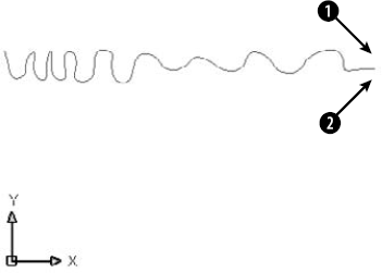
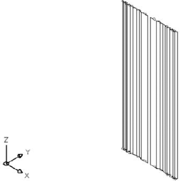
The TABSURF command takes an outline, or profile, which AutoCAD calls a path curve, and extrudes it along a vector that defines the direction and distance of the extrusion. Figure 23.26 shows two examples of extruded surfaces.
Note
The TABSURF command now creates a mesh object by default. You can create a polyface or polygon, or full-feature meshes by setting the MESHTYPE system variable's value to 0. Mesh objects are covered fully in Chapter 24.
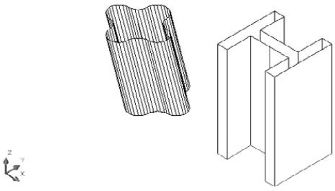
For the I-beam, you could have simply given the 2D polyline profile a thickness and achieved a similar result. However, you could not have done so with the extruded surface on the left, because the extrusion is not perpendicular to the XY plane that contains the 2D polyline profile. TABSURF can extrude a shape in any direction.
When you select the vector object, your pick point determines the direction of the extrusion. AutoCAD starts the extrusion from the end of the vector closest to the pick point.
You use the SURFTAB1 system variable to control the number of lines AutoCAD uses to display the curve. If the curve is made up of polyline segments, AutoCAD displays one line at each segment vertex.
Warning
Note the I-beam in Figure 23.26. If you create an object by mirroring, stretching, and so on, you'll see extra tabulation lines at the separate segments in the polyline definition. If you want a clean look, you need to draw clean. You could use the original shape as a guide to draw a new polyline on top of the old one, and then erase the original.
You should use a nonplanar view when using TABSURF to check that you've accurately defined the extrusion vector into the third dimension. Any of the preset isometric views are helpful.
To draw an extruded surface, follow these steps:
Draw the object to extrude — a line, arc, circle, polyline, ellipse, or elliptical arc. This is the path curve.
Draw the vector, usually a line. If you use a 2D or 3D polyline, AutoCAD uses an imaginary line from the start point to the endpoint to determine the vector.

At the
Select object for path curve:prompt, select the path curve object.At the
Select object for direction vector:prompt, select the line that you're using for the vector.
Note
The drawing used in the following exercise on drawing tabulated surfaces, ab23-e.dwg, is in the Drawings folder on the DVD.
STEPS: Drawing Tabulated Surfaces
Open
ab23-e.dwgfrom the DVD.Save it as
ab23-05.dwgin yourAutoCAD Biblefolder. You see a tabletop. Its bottom is at a Z height of 30. The current elevation is 30. You're looking at the table from the SE isometric view. Object Snap should be on. Set running object snaps for Endpoint, Midpoint, and Center. The current layer isConst. The drawing is shown in Figure 23.27.Start the CIRCLE command. Follow the prompts:
Specify center point for circle or [3P/2P/Ttr (tan tan radius)]:
Choose the From object snap. _from Base point:Pick the endpoint atin Figure 23.27. <Offset>:@-1,3Specify radius of circle or [Diameter]:.75Start the LINE command. At the
Specify first point:prompt, choose the Center object snap of the circle that you just drew. At theSpecify next point or [Undo]:prompt, type 3,−3,−30
Start the MIRROR command. Select the entire leg. Choose the Midpoint of the bottom edge of both long sides of the table for the two points of the mirror line.
Repeat the MIRROR line and select both legs. Mirror them by using the Midpoints of the bottom edge of the short sides of the table for the two points of the mirror line.
Do a ZOOM Extents to see the entire table.
Save your drawing. It should look like Figure 23.28.
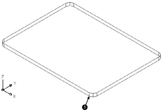
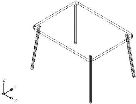
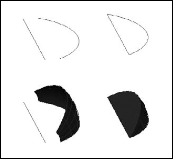
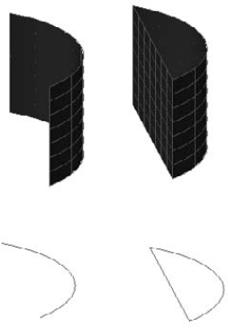
Figure 23.29 shows an open 2D figure (an arc) and a closed figure (a line and an arc), and the results after using the EXTRUDE command.
Sweeping is similar to extruding, but you have more options. Like the EXTRUDE command, the SWEEP command creates surfaces when you sweep an open profile and solids when you sweep a closed one.
If you have two existing objects, you may want to define the surface that would extend between these objects. Or, you may want to extrapolate a surface along two or more objects. You can use two commands to create these surfaces.
Use the RULESURF command to create a surface that extends between two 2D objects. The objects can be lines, polylines (2D or 3D), circles, ellipses, elliptical arcs, splines, or points. The two objects must be either both open or both closed. Only one of the two can be a point.
Use the SURFTAB1 system variable to control the number of lines that AutoCAD uses to display the surface. Figure 23.31 shows some ruled surfaces.
Note
The RULESURF command now creates a mesh object by default. You can create a polyface or polygon, or full-feature meshes by setting the MESHTYPE system variable's value to 0. Mesh objects are covered fully in Chapter 24.
The pick points of the two objects affect the resulting curve. If you pick them both on the same side, you get the type of curves shown on the left in Figure 23.31. If you pick them on opposite sides, the curve intersects itself, as shown on the right in Figure 23.31.
Follow these steps to draw a ruled surface:
Draw the two objects for the ruled surface.

At the
Select first defining curve:prompt, choose the first object.At the
Select second defining curve:prompt, choose the second object.
Note
The drawing used in the following exercise on drawing ruled surfaces, ab23-f.dwg, is in the Drawings folder on the DVD.
STEPS: Drawing Ruled Surfaces
Open
ab23-f.dwgfrom the DVD.Save it as
ab23-06.dwgin yourAutoCAD Biblefolder. You see a spline, as shown in Figure 23.32. In this exercise, you use the spline to draw some drapes.Mirror the spline. For the mirror line, turn on Ortho Mode and use
Start the COPY command and select both splines. At the
Specify base point or [Displacement/mOde] <Displacement>:prompt, type 0,0,73Choose Home tab

Repeat the RULESURF command. At the
Select first defining curve:prompt, choose the top-left spline near its left endpoint. At theSelect second defining curve:prompt, choose the bottom-left spline near its left endpoint.Save your drawing. It should look like Figure 23.33.
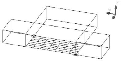
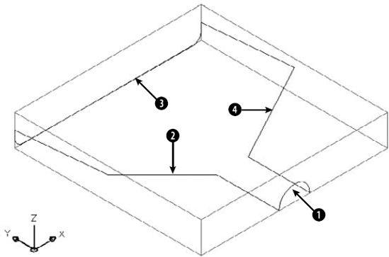
You may have several edges and want to create a surface that extends between them. You can use the EDGESURF command to create unusual surfaces bound by four touching objects. The objects can be lines, arcs, splines, or polylines (2D or 3D). EDGESURF creates a polygon mesh that approximates a Coon's surface patch mesh — a surface defined by four edges. Figure 23.35 shows an edge surface.
Note
The EDGESURF command now creates a mesh object by default. You can create a polyface or polygon, or full-feature meshes by setting the MESHTYPE system variable's value to 0. Mesh objects are covered fully in Chapter 24.
Use the SURFTAB1 and SURFTAB2 system variables to vary the displayed lines in each direction.
Follow these steps to create an edge surface:
Draw the four objects to create a boundary for the surface. They must touch, so use Endpoint object snaps to create them or to move them into place.

AutoCAD prompts you to select edges 1 through 4. You can select them in any order.
Creating the four edges involves moving from one UCS to another UCS because they're all in 3D. It helps to create a bounding box for your object by using the BOX command. You can then use the dynamic UCS feature to temporarily change UCSs for each edge.
Note
The drawing used in the following exercise on drawing edge surfaces, ab23-g.dwg, is in the Drawings folder on the DVD.
STEPS: Drawing Edge Surfaces
Open
ab23-g.dwgfrom the DVD.Save it as
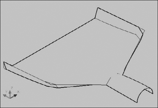
ab23-07.dwgin yourAutoCAD Biblefolder. You see four curves in a bounding box, as shown in Figure 23.36. In this exercise, you use the curves to draw a dustpan.Freeze the Const layer.

Choose Home tab
Save your drawing. It should look like Figure 23.37. It's either a dustpan or a starship — your choice.
Several commands convert one type of object to another or allow you to use multiple types of objects together. For example, you can convert 2D objects to surfaces and surfaces to solids.
Perhaps the simplest way to create a surface is to convert an existing object to a surface. The CONVTOSURFACE command allows you to do just that. You can convert the following objects to surfaces:
2D objects created with the SOLID command
Regions
Zero-width polylines with thickness and that don't create a closed figure
Lines and arcs with thickness (covered in Chapter 21)
Warning
By default, the original objects are deleted. You can control this by using the DELOBJ system variable, which determines whether objects that are used to create other objects are deleted. To keep the original objects, change the value of DELOBJ to 0 (zero). (The default value is 1, which deletes the objects.) You can set the value to −2 to prompt you and allow you to decide if you want to delete the original objects.
Objects that you create by using the PLANESURF, REVOLVE, EXTRUDE, SWEEP, and LOFT commands are called smooth surfaces to distinguish them from polygon or polyface mesh surfaces. You can control how mesh objects are converted to solids and smooth surfaces by using the SMOOTHMESHCONVERT variable. To set the system variable, choose Mesh Modeling tab
The THICKEN command allows you to add thickness to a surface and thereby turn it into a solid. You can only use it on surfaces created with the PLANESURF, EXTRUDE, SWEEP, LOFT, or REVOLVE command. However, you can start with a region, line, or arc — using CONVTOSURFACE, for example, to create a surface — and then use THICKEN to turn it into a solid.
To thicken a surface to a solid, follow these steps:

Select the surface or surfaces that you want to thicken.
At the
Specify thickness <0.0000>:prompt, enter a thickness. A positive number thickens in the positive direction of the axes; a negative number thickens in the negative direction.
Extrudedsurface
Loftedsurface
Revolvedsurface
Planesurface
You cannot convert polygon or polyface meshes. Figure 23.38 shows edges extracted from a lofted surface.
You can also select individual edges or faces to extract by pressing the Ctrl key and clicking the edges or faces that you want. Then use the XEDGES command to extract them.
Note
You can use the SLICE command to slice a solid with a surface. I cover the SLICE command in Chapter 24.
In this chapter, you read all about 3D surfaces. You read about:
Creating surfaces by using the 3DFACE command and controlling the visibility of the lines between the faces
Creating polyface meshes
Creating plane surfaces
Drawing surfaces with 3D polygon meshes, including the basic shapes — box, wedge, pyramid, cone, sphere, dome, dish, and torus
Making a surface by revolving a profile around an axis
Extruding and sweeping a curve
Creating a surface between two curves
Making an edge surface from four curves
Working with multiple types of objects
In the next chapter, you discover how to create true solids and meshes (well, true electronic ones, at least) as well as how to edit in 3D.