
Every drawing includes text that labels or explains the objects in the drawing; this text is often called annotation. In each release, the capabilities of the text feature have improved so that you can now easily format and edit text to provide a professional appearance to your drawing. A wide range of font, alignment, and spacing options is available. You can also import text from a word processor. This chapter tells you all that you need to know about creating text in AutoCAD and AutoCAD LT.
A great deal of text in a drawing consists of short labels or comments. Use single-line text when you want each line of text to be a separate object or when you're creating a small amount of text. Single-line text has fewer options than the multiline text that I explain later in this chapter, but it's easy to create and accurately place in a drawing.
Follow the prompts:
Current text style: "Standard" Text height: 0.2000 Annotative: No Specify start point of text or [Justify/Style]:Pick a start point for the text. Specify height <0.2000>:Type a height, or pressEnter to accept the default. Specify rotation angle of text <0>:Type a rotationangle, or press Enter to accept the default.
You see a cursor at the insertion point. Type one line of text. PressEnter. You can continue to type more lines of text.Press Enter again to end the command.You can also click anotherlocation on the screen to start a new text object.
Note
You cannot use the Return (usually the right) button of the mouse or the Spacebar to end the command. You can type -text on the command line to use the original TEXT behavior, which ends the command after one line of text. You must use the TEXT command (rather than the DTEXT command) for script files, menus, or AutoLISP routines. (See Parts VI and VII of this book for more information.)
The next section covers the Justify option. The Style option and the Annotative property are discussed later in this chapter.
One advantage of DTEXT is that each line of text is a separate object, making it easy to move or copy individual lines of text. Unfortunately, you cannot control the spacing between the lines.
Note
It (for the TEXT command) and Idt (for DTEXT) allow you to specify the spacing between lines of text as you create them. Look in SoftwareChapter 13It. Txtstack, in SoftwareChapter 13 xtstack, adjusts spacing between lines of single-line text. You can use txt2mtxt to convert single-line text to multiline text. Look in SoftwareChapter 13 xt2mtxt. These programs work only in AutoCAD. (Thanks to Leonid Nemirovsky, home.pacifier.com/˜nemi, for creating It.lsp and Idt.lsp at my request.)
DTEXT remembers the location of the previous line of text even if you've used other commands in the meantime. To continue text below the last line of text that you have created, press Enter at the Specify start point of text or [Justify/Style]: prompt.
When you pick a start point for text, the relationship between the start point and the actual letters is determined by the justification. The start point is also called the insertion point. When you want to refer to text by using object snaps, you use the Insertion object snap. If you select text without first choosing a command, grips appear at the insertion point as well as at the bottom-left corner.
By default, text is left-justified; therefore, there is no left justification option. To change the text's justification, right-click and choose Justify at the Specify start point of text or [Justify/Style]: prompt. The command responds with this bewildering prompt:
Enter an option [Align/Fit/Center/Middle/Right/TL/TC/TR/ML/MC/MR/BL/BC/BR]:
Align and Fit offer two ways to fit text into a specified space. Both respond with the same two prompts:
Specify first endpoint of text baseline:
Specify second endpoint of text baseline:
Specify the beginning and the end of the text line. Align then prompts you for the text and squeezes or stretches the text to fit within the text line. The height of the text changes accordingly, to maintain the proportions of the font.
Fit adds the Specify height <0.2000>: prompt. Type the height that you want and then type the text. Fit also squeezes or stretches the text to fit within the text line, but maintains the text height that you specified, distorting the font letters to fit the space. Figure 13.1 shows an example of normal, aligned, and fitted single-line text.

Here is an explanation of the other justification options:
Center. Text is centered around the insertion point. The insertion point is on the baseline.
Right. Text is right-justified from the insertion point. The insertion point is on the baseline.
Middle. Text is centered both vertically and horizontally. The vertical center point is measured from the bottom of the lowest to the top of the tallest possible letter.
TL, TC, TR. The insertion point is at the top of the highest possible letter, and the text is left-, center-, or right-justified, respectively.
ML, MC, MR. Text is centered vertically. The vertical center point is measured from the bottom of the lowest to the top of the tallest possible letter. Text is left-, center-, or right-justified, respectively.
BL, BC, BR. The insertion point is below the lowest descending letter. Text is left-, center-, or right-justified, respectively.
Tip
If you know the option abbreviation of the justification that you want, you can use it at the Specify start point of text or [Justify/Style]: prompt.
Setting the height of text is fairly straightforward. The default is 0.2 units. The main point to consider is the scale factor. If you're drawing a house and plan to plot it at 1″ = 8′ (1 = 96), you need to figure out how big to make the text so that you can still read it when it is scaled down.
For example, if you want the text to be 0.2 units high and your scale factor is 96, your text needs to be 19.2 inches high (0.2 × 96). On the other hand, if you're drawing a very small object, such as a computer chip, and your scale is 0.10, then your text needs to be 0.02 inches high.
AutoCAD and AutoCAD LT calculate text height in units. Most word processors calculate text height in points. A point is
You can create annotative single-line text, using an annotative text style. This feature automatically scales text according to your scale. For more information, see the section see the section "Understanding Text Styles" later in this chapter. To make existing single-line text annotative, select the text and change the Annotative property in the Properties palette from No to Yes. For more information about changing the scale of text, see the section "Editing single-line text" later in this chapter.
The final prompt in DTEXT is the rotation angle. This angle applies to the entire line of text, not to individual characters. (You can specify slanted text, called obliqued text, using the STYLE command covered later in this chapter.) Figure 13.2 shows text rotated to 315 degrees.
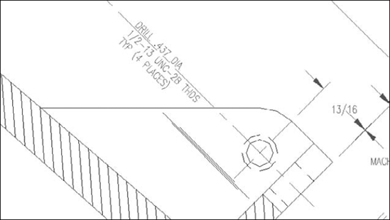
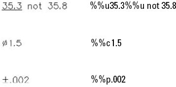
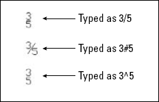
To create special characters and formats, you have to use codes. These codes are shown in Table 13.1.
Figure 13.3 displays text using some of these codes, along with the entries that created them.
Note
The drawing used in the following exercise on creating text with DTEXT, ab13-a.dwg, is in the Drawings folder on the DVD.
STEPS: Creating Text with DTEXT
Open
ab13-a.dwgfrom your DVD.Save the file as
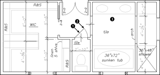
ab13-01.dwgin yourAutoCAD Biblefolder. This is a master-bathroom plan drawing, as shown in Figure 13.4. Make sure that Object Snap is on. Set running object snaps for Endpoint, Midpoint, and Intersection.
Current text style: ″ROMANS″ Text height: 0′−4 1/2″ Annotative: No
Specify start point of text or [Justify/Style]: Right-click and choose Justify.
Enter an option [Align/Fit/Center/Middle/Right/TL/TC/TR/ML/MC/MR/BL/ BC/BR]:
Right-click and choose BC. Specify bottom-center point of text:Use the Midpoint running objectsnap to pick
in Figure 13.4. Specify rotation angle of text <0>:Pick the endpoint at. Enter text:
2-0Enter text:
Start the DTEXT command again. Follow the prompts:
Specify start point of text or [Justify/Style]:
Right-click andchoose Justify. Enter an option [Align/Fit/Center/Middle/Right/TL/TC/TR/ML/MC/MR/BL/ BC/BR]:Right-click and choose Middle. Specify middle point of text:Pick
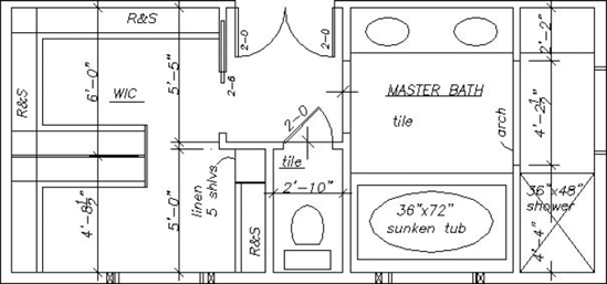
in Figure 13.4. (This pointdoesn't have to be exact.) Specify rotation angle of text <45>:0Enter text:%%UMASTER BATHEnter text:Save your drawing. It should look like Figure 13.5.
As with any drawing object, the need often arises to edit your text. The most common way to edit single-line text is to use the DDEDIT command. Double-click the text to start the command. Remember that each line of text created with DTEXT or TEXT is a separate object.
The text appears in a border with your text highlighted in an edit box, as shown in Figure 13.6. You can start typing to completely replace the text or click where you want to change part of the text and use standard Windows techniques to edit the text. Press Enter or click anywhere outside the border. DDEDIT prompts you to select another annotation object. Press Enter to end the command.

Tip
If you find other nearby or overlapping objects to be distracting, right-click and choose Editor Settings
You can also change text by using the Quick Properties palette. Select any text and click in the Contents item of the Quick Properties palette to edit the text. To use the Properties palette, select any text object and open the Properties palette (Ctrl+1). Here you can edit the text content as well as every other conceivable property, including layer, linetype, lineweight, color, insertion point, justification, rotation angle, and others that I cover in the section on text styles.
If you want to scale text and use the SCALE command, the text may move, depending on the base point you use. Instead, you can use the SCALETEXT command to change the scale of selected text without moving the text insertion point. This command works with either one text object or several at once. All the text objects stay in their original location.
To use SCALETEXT, follow these steps:

Select the text objects that you want to scale.
At the
Enter a base point option for scaling [Existing/Left/Center/Middle/Right/TL/TC/TR/ML/MC/MR/BL/BC/BR] <Existing>:prompt, press Enter to use the existing insertion point of the selected text, or choose a new base point. (Your last choice for this prompt becomes the new default, so if you used another option, type eAt the
Specify new model height or [Paper height/Match object/Scale factor] <3/32>:prompt, right-click and choose Scale Factor to specify a scale factor, just as you would for the SCALE command (see Chapter 9). You can also type a new height or use the Match Object option to match the height of the selected text objects to another existing text object. The prompt asks you to select an object with the desired height. For annotative text only, you can specify a paper height, which means the height you want the text to appear when plotted.If you have chosen the Scale Factor option, then type the factor that you want at the
Specify scale factor or [Reference] <2>:prompt.If you want to specify the scale factor with reference to existing text or a value, use the Reference option. At the
Specify reference length <1>:prompt, type a length or specify two points that measure the reference length. At theSpecify new length:prompt, type a value or pick two points to indicate the new length.
If you want to scale text to automatically fit a drawing scale, you can use annotative text. For more information, see the upcoming section "Understanding Text Styles."
Note
The drawing used in the following exercise on editing text, ab13-b.dwg, is in the Drawings folder on the DVD.
STEPS: Editing Text
Open
ab13-b.dwgfrom your DVD.Save the file as
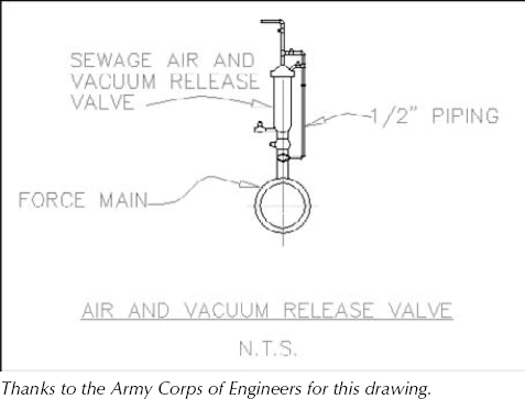
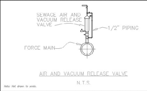
ab13-02.dwgin yourAutoCAD Biblefolder. This is an air and vacuum release valve, as shown in Figure 13.7.Double-click the text
1/2″ piping. A highlighted border appears around the text. Select only the text 1/2 and type 3/8. Press Enter or click anywhere outside the text border. The DDEDIT prompt continues to prompt you to select another annotation object. Press Enter to end the command.Display the Properties palette (Ctrl+1). Click Quick Select in the Properties palette. In the Quick Select dialog box, choose Text from the Object Type drop-down list. In the Operator drop-down list, choose Select All. Click OK to select all the text objects in the drawing.
In the Properties palette, choose Layer. From the Layer drop-down list, choose TEXT. Choose Color. From the Color drop-down list, choose ByLayer. All text is now on the TEXT layer using the ByLayer color. Press Esc to remove the grips and see the result.
Select the text at the bottom of the drawing that reads N.T.S. From the grips you can tell that it has a middle-left justification. Choose Annotate tab

The command ends. You can select the text again to see that the insertion point grip is now at the bottom center of the text.
Choose Annotate tab
Select objects:
Select the two lines of text at the bottom of the drawing. Select objects:Enter a base point option for scaling [Existing/Left/Center/Middle/Right/TL/TC/TR/ML/MC/MR/BL/BC/BR] <BC>:Typeeto use the existing base point. Specify new model height or [Paper height/Match object/Scale factor] <1/8″>:Right-click and choose Scale factor. Specify scale factor or [Reference] <2″>:Type1.5You can click the Properties palette's Close button to close it. Save your drawing.
You may not always want to use the default font. You can create text styles that give you full creative control over the font, font style (bold, italic, or both), character width, obliquing angle, and text height. You can even design backward, upside-down, and vertical text. (Vertical text is like the text that you occasionally see on the spine of a book. It goes down rather than to the right.)
Each text style
Has a name and several properties
Is saved with the drawing
Can be made current when you want to use it
Can be renamed and deleted
Creating text styles is part of the typical drawing setup procedure. You should include text styles in your drawing templates. AutoCAD and AutoCAD LT come with two types of fonts: the original .shx fonts, which are created by using shape files; and TrueType fonts, which are used by most Windows applications.
Note
See Chapter 32 for instructions on creating shape files and your own fonts.
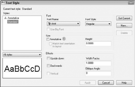
Choose New to open the New Text Style dialog box. Type the name of your new text style and click OK. Text style names can be up to 255 characters and can include spaces. You return to the Text Style dialog box where you can define the new text style.
At the top left of the Text Style dialog box is a list of currently defined styles in the drawing. At the lower-left corner is a preview of the style that is selected in the Styles list.
In the Font section of the Text Style dialog box, you specify the font name and font style. Click the Font Name drop-down list arrow to see the list of fonts. Fonts with the double-T icon are TrueType fonts. The other fonts are defined in a shape file that has the SHP filename extension. They are compiled into a file with the SHX filename extension for faster access. For more information on working with fonts, see Chapter 32.
Click a font to choose it and see a preview in the Preview pane at the lower-left corner of the dialog box. If the font that you've chosen supports different styles, such as bold or italic, you can choose one of them in the Font Style drop-down list. None of the AutoCAD or AutoCAD LT fonts supports font styles, but many of the TrueType fonts do.
The Size section of the dialog box lets you specify the height of the text. There are two types of height:
Height in the drawing. If you are going to use the text style in the main drawing area (model space, where you draw and edit), use the Height text box to enter the height of the text. Remember to take into account the scale factor, if necessary.
Height in a viewport. If you are going to use the text style for text that you will display in a scaled viewport on a layout, check the Annotative check box. Then use the Paper Text Height text box to enter the height of the text. You don't need to adjust for the scale factor when you enter a height, because annotative objects facilitate that process for you. I cover layouts and using annotative objects in Chapter 17.
Note
If you check the Annotative check box, you can also check the Match Text Orientation to Layout check box. If you rotate the viewport by using the MVSETUP command, with the Align
In both types of height, you can leave the height at zero if you want to be able to vary the text height within that one style. If the height is zero, the DTEXT and TEXT commands prompt you for a height when you use these commands to place text.
Warning
If you create a text style using a height other than zero and then use that text style when you define a dimension style, the text style height overrides the text height that you specify in the dimension style. See Chapter 15 for more information on dimension styles.
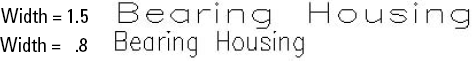
In the Effects section, you specify the orientation, width factor, and oblique angle of the text style. The default width factor of characters is set to 1. You can specify a smaller number to compress text and a larger number to expand it, as shown in Figure 13.9.
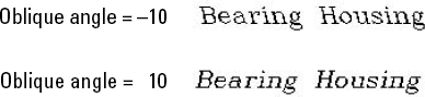
The term oblique angle refers to the angle of the individual letters. It is generally used to create an effect, such as italic text. You don't need to use an oblique angle if you're using a TrueType font that supports italic text.
The angle definition used to define oblique text is different from the angle definition used for other objects. Up and down text, which is normal text, has a zero oblique angle. A positive angle slants the text to the right; this is typical for italic text. A negative angle slants the text to the left. Figure 13.10 shows text with a positive and negative oblique angle.
You can create text that is backward (like a mirror image) or upside down. Some fonts also let you create vertical text. Figure 13.11 shows an example of each kind of text. Check the appropriate check box to create the effect that you want.
After you finish defining your text style, click Apply to make it current. Click Close to return to your drawing.
You can rename and delete text styles easily. To rename a text style, start the STYLE command to open the Text Style dialog box. Select the text style, click the text style's name again, enter a new name, and press Enter.
To delete a text style, choose it from the Styles box of the Text Style dialog box and click Delete. A message box asks you to confirm the deletion. Click OK to delete the text style. You cannot delete a text style that is being used.
Note
The drawing used in the following exercise on creating text styles, ab13-b.dwg, is in the Drawings folder on the DVD.
STEPS: Creating Text Styles
Open
ab13-b.dwgfrom your DVD.Save the file as
ab13-03.dwgin yourAutoCAD Biblefolder.
From the Font Name drop-down list, choose
romans.shx″. In the Height text box, enter a height of 1/16″. In the Width Factor text box, enter a width factor of .95. In the Oblique Angle text box, type 10. Click Apply to make the new style current. Click Close.Start the DTEXT command. At the
Specify start point of text or [Justify/Style]:prompt, pick a start point at the lower-left corner of the drawing. At theSpecify rotation angle of text <0>:prompt, press Enter. At the prompt, type Note: Not drawn to scale.Save your drawing. It should look like Figure 13.12. If you're going on to the next exercise, keep this drawing open.
To change a style, choose Home tab
Note
Unfortunately, only changes to the font and text style affect current text. Other changes, such as width factor, oblique angle, orientation, and height, are ignored. However, new text takes on these other changes.
You can choose the current style when you use one of the text commands. If you use DTEXT or TEXT, the command displays the Specify start point of text or [Justify/Style]: prompt. Right-click and choose Style. (The prompt also displays the current style, height, and annotative setting.) If you know the name of the style that you want to use, type it and press Enter. The Specify start point of text or [Justify/Style]: prompt repeats. You can choose the Justify option or pick a start point to continue the command.
If you use MTEXT, the In-Place Text Editor opens, as explained in the next section. Choose the text style that you want from the Style drop-down list.
An easy way to make a style current or to change the text style of existing text is to choose Home tab
As explained in Chapter 11, you can use the DesignCenter to import features from other drawings. To import a text style, follow these steps:
Open the DesignCenter (Ctrl+2).
In the left pane, navigate to the drawing that has the text style that you want.
Double-click the drawing icon or click its plus sign.
To see the list of the text styles, double-click the text style's icon in either the left or right pane.
Double-click the text style's icon in the right pane to import it into your drawing.
Note
The drawing used in the following exercise on modifying text styles, ab13-03.dwg, is in the Results folder on the DVD.
STEPS: Modifying Text Styles
If you have
ab13-03.dwgopen from the previous exercise, continue to use it for this exercise. Otherwise, openab13-03.dwgfrom theResultsfolder of your DVD.Save the file as
ab13-04.dwgin yourAutoCAD Biblefolder.The note at the bottom-left corner of the drawing uses the Notes text style. Choose Home tab
The drawing regenerates, and the font of the text changes.
Save your drawing.
Single-line text is awkward when you want to type quite a bit of text. The main disadvantage is that single-line text does not wrap text to the next line to keep a neat right margin. Multiline text solves this problem and also offers many more formatting options compared to single-line text. The entire paragraph of multiline text is one object. Don't confuse multiline text, which is also called paragraph text, with multilines (which I cover in Chapter 16).
Current text style: ″ROMANS″ Text height: 4 1/2″ Annotative: No
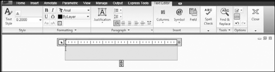
The command continues with the Specify first corner: prompt. Specify one corner of a bounding box to indicate where to place the text. At the Specify opposite corner or [Height/Justify/Line spacing/Rotation/Style/Width/Columns]: prompt, specify the diagonally opposite corner of the bounding box. The Text Editor tab appears on the ribbon. You can choose one of the other prompt options to specify the text properties before you type the text. Some of these options are also available in the In-Place Text Editor, which opens after you specify the bounding box. Figure 13.13 shows the In-Place Text Editor.
Note
The size limit for multiline text has increased from 32 kilobytes to 256 kilobytes, enabling you to insert much larger blocks of text into your drawing.
Note
If you are using the AutoCAD Classic workspace, the In-Place Text Editor tools appear on a separate toolbar, instead of on the ribbon (which isn't displayed in that workspace). For more information on workspaces, see Chapter 1 and Appendix A. The same tools are available, but their order on the toolbar is different. You can also use the MTEXTTOOLBAR system variable to control the display of the Mtext Format toolbar. Change its value to 1 to display the MText toolbar rather than the ribbon tab.
Tip
When you specify the corners of the Mtext bounding box, you see sample text at the cursor to give you an idea of the actual current height of the text. You can change the sample text with the MTJIGSTRING system variable.
Type your text in the bounding box. The In-Place Text Editor wraps the text to the next line when the text meets the right side of the bounding box that you specified. Although you've created a bounding box with four sides, only the paragraph width (that is, the left and right margins) limits the text. If you type too much text for the bounding box, the bounding box expands vertically. To format selected or new text, use the buttons on the panels of the Text Editor tab of the ribbon. In the Style panel, you can do the following:
In the Formatting panel, you can do the following:
Bold. If Bold style is supported for the font, select text and click the Bold button.
Italic. If Italic style is supported for the font, select text and click the Italic button.
Overline. To overscore selected text, click the Overline button.
Color. Choose ByLayer or any color from the Color drop-down list. To choose from additional colors, choose Select Color to open the Select Color dialog box. (See Chapter 11 for details on using this dialog box.)
Make Uppercase. Click to make selected text all uppercase.
Make Lowercase. Click to make selected text all lowercase.
Background Mask. Opens the Background Mask dialog box. This feature creates a background around your text that covers other objects so that you can easily read the text. Check the Use Background Mask check box. Specify a border offset factor to create a margin around the text. A margin setting of 1 does not create any margin. Then check the Use Drawing Background Color check box to use the color of your drawing screen, or choose another color from the drop-down list. Click OK.
Oblique Angle (in the expanded Formatting panel). Enter a number that represents an angle from upright to specify the angle for the selected characters. For example, you can use the oblique angle to create italicized text. A negative value angles text to the left.
Tracking (in the expanded Formatting panel). Enter a number in the text box to specify the spacing between letters of selected text. The number works like a scale factor.
Width Factor (in the expanded Formatting panel). Enter a number in the text box to specify the width of selected letters. The number works like a scale factor.
In the Paragraph panel, you can control formatting that applies to an entire paragraph, as follows:
Justification. Choose a justification from the Justification drop-down list. The justifications are discussed in the "Justifying single-line text" section earlier in this chapter.
Bullets and Numbering. Displays a submenu that lets you manage bullets and numbering:
Off. Removes bullets and numbering from the selected text.
Numbered. Creates a numbered list.
Lettered. Lets you create lettered lists. You can choose uppercase or lowercase letters.
Bulleted. Creates a bulleted list.
Start. Restarts numbering (or lettering) from the beginning.
Continue. Continues numbering (or lettering) from the last list.
Allow Auto-list. Automatically starts a numbered list if you type 1., a lettered list if you type A., or a bulleted list if you type a dash (−) or an asterisk (*).
Use Tab Delimiter Only. Creates a list only if you use a tab after some text, and not when you use a space. On by default.
Allow Bullets and Lists. Turns on the feature that automatically numbers (or letters) items that are in a list. For example, if you delete an item, the rest of the items are automatically adjusted.
Line Spacing. Set line spacing in multiples of single-line spacing. You can choose More to open the Paragraph dialog box, discussed later in this list.
Default. Sets the default alignment, usually left-justified.
Left. Left-justifies text and sets the insertion point to the left of the text.
Center. Centers text and sets the insertion point to the center of the text.
Right. Right-justifies text and sets the insertion point to the right of the text.
Justify. Aligns both the left and right margins on the text.
Distribute. Spreads out the text to meet the left and right margins.
Paragraph. Click the dialog box launcher arrow at the right side of the panel's title bar to open the Paragraph dialog box, shown in Figure 13.14, where you can specify the following settings:
Tabs. You can choose left, center, right, and decimal tabs, as well as their position. Click Add to add the tab. A decimal tab centers text around a decimal point. (If you choose a decimal tab, you can choose a decimal style from the Specify Decimal Style drop-down list — period, comma, or space.)
Paragraph Alignment. Check the Paragraph Alignment check box and choose Left, Center, Right, Justified, or Distributed. These buttons are also on the Paragraph panel.
Paragraph Spacing. Sets spacing between paragraphs. You can set spacing both before and after, but if you set both, the two values are added.
Left Indent. Sets the left margin for the first line of a paragraph and the rest of the paragraph. Use this indentation for creating bulleted and numbered lists. To indent an entire paragraph, use both first-line and paragraph indentation. You can also use the triangle indent markers on the Text Editor ruler.
Paragraph Line Spacing. You can set the spacing of lines of text within a paragraph. For example, from the Line Spacing drop-down list, you can choose Multiple to Single or Double-space lines. Choose Exactly to specify the distance between lines in units — great for inserting text into titleblocks. Choose At Least to set a minimum spacing ( this is good for situations when you have text or symbols of varying heights and want to leave room for the larger items. For simple formatting, you can use the Line Spacing button in the Paragraph panel.
Combine Paragraphs (on the expanded Paragraph panel). Combines separate paragraphs into one. Select the paragraphs that you want to combine before applying the command.
Tip
To set indentation and tabs on the In-Place Text Editor's ruler, drag the first-line indent marker (the top triangle at the left of the ruler) or the paragraph indent marker (the bottom triangle) to the left or right. To set a tab, click on the ruler where you want the tab. To delete a tab, drag a tab marker off the ruler. Note that the bullets and numbering feature makes these settings less important than previously.
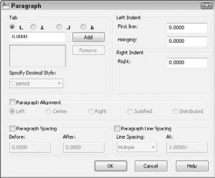
Figure 13.14. The Paragraph dialog box offers one place where you can specify many settings relating to paragraphs.
The Insert panel enables you to do the following:
Columns. Create multiple-column text. You have the following options:
No Columns. Creates one column of text.
Dynamic Columns. The default option, which creates columns based on the amount of text. Text automatically flows from one column to the next. The vertical height of the bounding box does not change as you add text; if you enter more text than can fit in the box, another column automatically starts, with no limit. You can set column height to automatic or manual (the default), using the submenu.
Static Columns. Creates a set number of columns of a specified height and width. Text automatically flows from one column to the next, but you can specify the number of columns.
Insert Column Break. Forces a column break. Place the cursor at the desired location and press Alt+Enter.
Column Settings. Opens the Column Settings dialog box. Here you can specify the type of columns, their width, height, and gutter (the spacing between columns).
Tip
You can grip-edit column text. Use one of the lower grips to change the vertical height. Use the right-facing arrow to change the column width.
Symbol. Insert the degree, plus/minus, or diameter symbol, a non-breaking space, and a number of other symbols. You can also choose Other to open the Windows Character Map to select any of the available symbols. Click a symbol, and then click Select. Click Copy and then click the Close button to close the Windows Character Map. In the In-Place Text Editor, press Ctrl+V to paste the symbol.
Field. Insert a field into the text. For more information, see the section "Inserting Fields" later in this chapter.
In the Spell Check panel, you can do the following:
Spelling Check. Find misspelled words in the selected Mtext object. Be sure to place the cursor at the beginning of the text. Misspelled words are underlined with a dashed red line. You can then right-click to choose from suggested words. At the end of this chapter, I explain how to check the spelling of an entire drawing.
Edit Dictionaries. You can edit the dictionaries that AutoCAD and AutoCAD LT use to check spelling. I discuss this process at the end of this chapter.
In the Tools panel, you have the option to do the following:
Find and Replace. Open the Find and Replace dialog box so that you can find or replace specified text. If you want the search to match the case of the specified text, choose Match Case. If you want to restrict the search to whole words that match the specified text, choose Find Whole Words Only. If you only want to find text, ignore the Replace text box. To both find and replace text, enter text in both boxes. Make sure that the cursor is at the beginning of the text if you want to search the entire Mtext object. At the end of this chapter, I explain how to find and replace text in an entire drawing.
Tip
You can check the Use Wildcards check box and use wildcards, such as * (any number of characters) and ? (any single character) to search for text. You can check the Match Diacritics check box to match words with diacritical marks. Finally, you can check the Match Half/Full Width Forms check box to refine searching for text in East Asian languages.
Import Text (on the expanded Tools panel). Opens the Select File dialog box, which lets you choose a text (TXT) or Rich Text Format (RTF) file to import. (Rich Text Format preserves formatting from application to application, while text-only documents do not retain formatting.) Find the file, choose it, and click Open to place the text in the In-Place Text Editor. The maximum file size is 256K. I cover other techniques for importing text later in this chapter.
AutoCAPS (on the expanded Tools panel). Automatically changes newly typed and imported text to uppercase, even if the Caps Lock key is not on. (And it's a cute pun on AutoCAD.)
On the Options panel, you can find the following:
Character Set (on the More drop-down list). Lets you choose the language that you want to work with, so that you have the characters that you need for that language.
Remove Formatting (on the More drop-down list). Removes character formatting, such as bold and italic, paragraph formatting (such as indenting), or all formatting.
Editor Settings (on the More drop-down list). Opens a submenu that lets you toggle the display of the main toolbar, the Options toolbar, and the ruler. You can also create a temporary opaque background for the In-Place Text Editor that may help you to edit text more easily if the text overlaps other objects. This background disappears when you close the editor. Finally, you can choose the color of the highlight when you select text.
Ruler. Turn the ruler on and off.
Undo. Undo the last Mtext edit.
Redo. Redo the last undo operation.
In the Close panel, click Close Text Editor to close the editor. You can also close the editor by clicking anywhere outside the editor or by pressing Ctrl+Enter.
Right-click in the editor to display the shortcut menu. The shortcut menu contains many of the options that are on the ribbon. Here I discuss the options that are not available on the ribbon.
Select All. Selects all the text in the current MText object.
Cut. Places selected text in the Windows Clipboard and removes it from the editor.
Copy. Places selected text in the Windows Clipboard without removing it from the editor.
Paste. Places text from the Windows Clipboard.
Paste Special. Opens a submenu where you can paste without character formatting, paragraph formatting, or any formatting at all.
Stack/Unstack. Toggles stacking and unstacking fractions. (This option only appears if you select appropriate characters.) Use this option to stack characters if they are not numerals or immediately before or after the three AutoStack symbols (slash, pound sign, and carat). Select the text, right-click, and choose Stack or Unstack. If you select stacked fractions, you can also choose Stack Properties to configure the fraction in the Stack Properties dialog box. See the sidebar, "Creating stacked fractions automatically," for more details on creating fractions.
Tip
To create an exponent (or superscript), type a number and then a carat, as in 2^. Select the number and the carat, right-click, and then choose Stack or Unstack. To create a subscript, type a carat, and then the number, as in ^2, and then stack it.
The TEXTTOFRONT command moves all text in your drawing to the front (top) of the drawing order. For the background mask to work, your text needs to be on top, so that you can use this command when you are creating text with background masks. The display order of objects is controlled by the DRAWORDER command, which I discuss in Chapter 27.
You can snap to the corners of the Mtext bounding box by using the node object snap. (See Chapter 4 for an explanation of object snaps.) To turn this feature off, change the OSNAPNODELEGACY system variable to 1.
Creating stacked fractions automatically
You can create automatic stacked fractions and tolerances as you type by using a system similar to those described earlier for creating special characters with DTEXT/TEXT.
You can also type unstacked fractions (as in 1/2), select the fraction text, right-click, and choose Stack or Unstack. To create stacked fractions as you type, open the In-Place Text Editor and follow these steps:
Type the numerator, which is the character that you want on top.
Type the character that defines the fraction format that you want (see the example):
Type a slash (/) to create a fraction separated by a horizontal line.
Type a pound symbol (#) to create a fraction separated by a diagonal line.
Type a carat (^) to create a tolerance stack, which is like a fraction separated by a horizontal line, except that there is no horizontal line.
Type the denominator.
Type a space (or other nonnumeric character). The AutoStack Properties dialog box opens.
Choose the option you want to create the stacked fraction:
Uncheck Enable AutoStacking to disable the automatic stacked fraction feature.
Uncheck Remove Leading Blank if you want to retain a space between whole numbers and fractions.
Choose whether you want the slash to result in a fraction with a horizontal line or a fraction with a slash. This choice does not affect how the pound sign and carat work. If you want the slash to result in a fraction with a slash (which would seem to make more sense), then you do not have an automatic way to create a fraction with a horizontal line.
Check Don't Show This Dialog Again; Always Use These Settings to stop the dialog box from opening when you create automatic stacked fractions.
Click OK to create the stacked fraction, or Cancel to leave the numbers as you typed them.
AutoStack works only with numerals immediately before and after the slash, pound sign, and carat. You can also set the properties of individual stacked fractions. Select and right-click the fraction in the In-Place Text Editor and choose Stack Properties from the shortcut menu. In the Stack Properties dialog box, you can change the following properties:
Text. Edit the upper and lower text.
Style. Change the fraction style. (Refer to the example under Step 2 for the three possible styles.)
Position. Position the fraction so that the top, center, or bottom is aligned with other text.
Text Size. Change the size of the numbers that make up the fraction. Fraction numbers are usually smaller than regular numbers.
You can specify the spacing between lines in multiline text before you open the Multiline Text Editor. (You can also use the Paragraph dialog box when you're in the editor, as described previously.) Line spacing is useful for fitting text into a schedule or table in your drawing. Of course, you can also use the table feature, which I discuss in the "Creating Tables" section later in this chapter. To set line spacing to an exact unit distance, follow these steps:
Start the Mtext command.
At the
Specify first corner:prompt, pick the first corner of your Mtext box.At the
Specify opposite corner or [Height/Justify/Line spacing/Rotation/Style/Width/Columns]:prompt, choose the Line Spacing option.At the
Enter line spacing type [At least/Exactly] <Exactly>:prompt, choose Exactly.At the
Enter line spacing factor or distance <1x>:prompt, type a number, such as 1 for specifying a one-unit space between lines of text. (If you type 1x, you get single-line spacing, which varies according to the size of the text.)Continue with the command.
This setting persists for future Mtext objects. To change existing line spacing, select (but do not double-click) the multiline text object. Open the Properties palette and set one or more of the following:
Line space factor. Specifies line spacing as a multiple of lines. Single-line spacing is 1.0000, and double-line spacing is 2.0000.
Line space distance. Specifies line spacing in units. Use this measurement (along with a line space style of Exactly) to fit text into an existing table or schedule.
Line space style. Choose At Least (the default) to adjust line spacing based on the height of the largest character in the line of text. Choose Exactly to specify line spacing that is the same, regardless of differences in character height.
To change the width of an Mtext object, you can use its right triangular grip. Select the Mtext object and drag the grip to the desired location.
You can use the Properties palette to change the width and height. You can specify the exact width when creating the Mtext object by using the Width option after you specify the first corner of the Mtext bounding box. Otherwise, you generally specify the width by picking the two corners of the Mtext bounding box.
Tip
When the In-Place Text Editor is open, you can change the width of the Mtext object by dragging on the right edge of the ruler.
To rotate an existing Mtext object, use the Properties palette's Rotation item, or use the top-left square grip, as follows:
You can also specify the rotation while creating the Mtext object. Use the Rotation option that appears on the command line after you specify the first corner.
You may plan to display certain sections of your drawing at more than one scale. For example, you may want to show the entire model at a 1:4 scale, but a detail of the model at a 1:1 scale. If you have some text next to the model and want that text to appear at both scales, you have a problem — (how do you get the text to appear the same size in both places? Without addressing this problem, your text will be either too big or too small at one of the scales. Another situation may be that you want one text object to appear at one scale, but another to appear at a different scale.
You create displays of various scales by using floating viewports on a layout. I cover viewports and layouts in Chapter 17, and you'll find further coverage of this topic there. However, if you know the scales you want to use, you can plan for this situation while you're in the drawing and editing stage by using annotative text.
Annotative objects create representations at various scales that you can automatically display at those scales when you lay out your drawing for plotting. The following objects can be annotative: text, tables, dimensions, tolerances, multileaders, blocks, and attributes. Text styles, dimension styles, and table styles can also be annotative; if you create an object using an annotative style, then the object is annotative. See the chapters that cover each of these objects for more information on their annotative property.
Previously, to create text that appeared in viewports of different scales, you needed to create a separate layer for each scale. You could then put the text on different layers and turn off the layers that you didn't want in each viewport. You might also have created separate text styles for each text object. This was a complicated and time-demanding task. Annotative text can eliminate the need for separate layers and text styles when you need to display text at more than one scale.
To create annotative text, follow these steps:
Create an annotative text style and make it current. To create an annotative text style, see the "Understanding Text Styles" section earlier in this chapter. AutoCAD also comes with a text style named
Annotativethat you can use.Decide on the scales that you will use for each text object. For example, you might have two text objects each at a different scale, or one text object that you need to display at two different scales.

Set the annotation scale for the first text object. To do so, click the Annotation Scale button at the right side of the status bar to display the scale list and choose the scale you want. For example, choose 1:4 if you plan to display the text in a viewport at the 1:4 scale. (The first time you add an annotative object to a drawing, a dialog box may open automatically, asking you for the scale.)
Note
In Chapter 15, I explain scales in general and how to edit the scale list.
Start the DTEXT or MTEXT command and enter the text.
Repeat Steps 4 and 5 for each separate scale and text item.
When you're ready to plot, you can set the desired annotative scale, and plot. You can also create viewports and set their scale. See Chapter 17 for details and an exercise using annotative objects.
If you want one text object to have more than one scale, you can add an annotative scale to it. Follow these steps:
Select the text.
Choose Annotate tab
Click Add to display the Add Scales to Object dialog box, where you can choose one or more scales.
Click OK twice to close both dialog boxes.
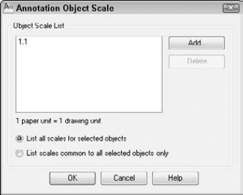
Figure 13.15. You can add or delete scales for annotative objects in the Annotation Object Scale dialog box.
If you want to change a text object that is not annotative to one that is annotative, you can use the Properties palette. Follow these steps:
Select the text.
Display the Properties palette.
In the Properties palette, select the Annotative property and choose Yes from the drop-down list. The Annotative Scale property is displayed in the Properties palette when the Annotative property is set to Yes.
Select the Annotative Scale property and click the Ellipsis button that is displayed to open the Annotation Object Scale dialog box, shown in Figure 13.15.
Click Add to display the Add Scales to Object dialog box, where you can choose one or more scales.
Click OK twice to close both dialog boxes.
To edit paragraph text, double-click the text to start the In-Place Text Editor.
Make your changes in the editor. The techniques are similar to those in any word processor. You can:
Select text and press the Delete key to delete the text, or type to replace the selected text.
Click to move the insertion point to where you want to insert text and start typing. (To type over text, press Insert to enter overtype mode.)
Use the ribbon or shortcut menu (right-click) to change formatting.
To change characters, you must first highlight the characters. This lets you make height or font changes to individual words or even letters. When changing properties that affect the entire paragraph, such as justification, you do not first highlight the characters.
If you right-click in the In-Place Text Editor with the cursor on a field, you have options to edit the field, update it, or convert it to regular text. For more information about fields, see the section "Inserting Fields" later in this chapter.
Note
Mmt combines two MText objects into one MText paragraph. Look in SoftwareCh13Mmt on the DVD. Txtexport exports text to a text file. It's in SoftwareChapter 13 xtexprt. These features work with AutoCAD only.
As mentioned earlier, you can import text by using the In-Place Text Editor. You can also import text in three other ways:
You can use drag-and-drop to insert text from a .txt file into a drawing. Open Windows Explorer and locate the file. Position the Explorer window so that you can see the filename and your drawing at the same time. Click the file and drag it to your drawing. The new text becomes multiline text in the drawing.
You can copy text from another file to the Windows Clipboard. Open the other file, select the text, and copy the text to the Windows Clipboard. Return to your drawing by clicking the AutoCAD or AutoCAD LT button on the Windows task bar. Choose Home tab
If you have the In-Place Text Editor open, you can paste the text directly into the editor. Right-click in the editor and choose Paste (or press Ctrl+V). You can then format the text.
Note
For more information on importing text, see Chapter 27.
Note
The files used in the following exercise on creating multiline text, ab13-c.dwg and ab3-c.txt, are in the Drawings folder on the DVD.
STEPS: Creating Multiline Text
Open
ab13-c.dwgfrom your DVD.Save the file as
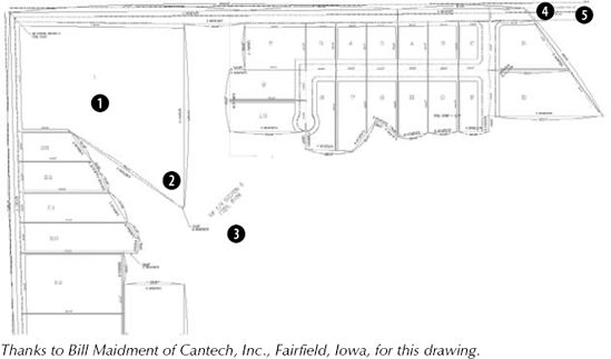
ab13-05.dwgin yourAutoCAD Biblefolder. This is a plat drawing, as shown in Figure 13.16.Choose Home tab
Containing 108.33 acres including 5.97 acres existing R.O.W. and 4.56 acres proposed R.O.W.
Highlight the text 108.33 and click Underline in the Formatting panel. In the Paragraph panel, choose Justification
Open Windows Explorer (Start
Select the text and open the Properties palette (Ctrl+1). Next to the Defined Width item, type 500
Zoom in on the new text. This text was originally single-line text in an older drawing. You can see why you wouldn't want to retype it!
Choose Zoom from the status bar and type p
Above the text about the proposed R.O.W. (right of way) is a yellow centerline. You want to place text on that line. Choose Home tab
At the prompt, pick

64TH AVE N.W. EXISTING R.O.W. 66' – CURRENT
Press the Spacebar to add a space after
CURRENT. From the Insert panel, choose SymbolTo add a background mask so that the yellow centerline doesn't make the text hard to read, choose Background Mask from the Formatting panel. In the Background Mask dialog box, select the Use Background Mask check box. Choose Red as the background color and click OK. Click anywhere outside the In-Place Text Editor to place the text. You can see that it uses the centerline symbol and has a red background that hides the yellow centerline behind the text.
Start the MTEXT command. At the prompts, define a border somewhere in the middle of the drawing. The width should be equal to about three of the plats that you see at the top. Type Plat Acreage
Type 1., press Tab, and type 22.93
Finish the rest of the numbered list as follows:
2. 2.853. 1.514. 1.38Click anywhere outside the In-Place Text Editor area to end the MTEXT command.
Zoom to the Previous display to return to your original view. Save your drawing.
Tables, which are often called schedules, are very common in drawings. You can save your formatting in table styles for consistency among drawings. You should save table styles in your templates.
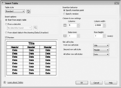
On the left side of the Insert Table dialog box, you see a preview of how the table will look. By default, you see either the Standard table style or the last table style that you used. Choose the table style that you want from the Table Style name drop-down list. In the next section, I explain how to define a table style.
In the Insert Options section, you can choose from three options for getting data into the table:
Start from empty table. Use this option when you want to manually enter the data.
From a data link. This option creates a table from Microsoft Excel spreadsheet data or a comma-delimited (CSV) file. When you choose this option, most of the rest of the Insert Table dialog box is unavailable.
From object data in the drawing (Data Extraction). This option creates a table from properties of existing objects in the drawing (AutoCAD only).
If you choose to start from an empty table, you can choose from one of the following options in the Insertion Behavior section of the dialog box:
Specify insertion point. You place the table in your drawing by specifying an insertion point (the default). You use the Column & Row Settings section to specify the number of columns and their width, as well as the number of rows and their height (in terms of lines of text).
Specify window. You pick a point at the upper-left and then lower-right corner of the table. You use the Column & Row Settings section to specify the number of columns and the line height of the rows. As you move the mouse to the right, the columns widen, and as you move the mouse downward, additional rows are added. Click when you see the size that you want.
In the Set Cell Styles section, you specify which cell styles go where. See the next section for an explanation of cell styles. By default, the First Row Cell Style uses the Title cell style, the Second Row Cell Style uses the Header cell style, and All Other Row Cell Styles use the Data cell style. If you create your own cell styles, you can choose them from the drop-down lists here.
If the table style shown is what you want, click OK. Then specify an insertion point or window to place the table.
Note
You can also add a table to a tool palette and insert a table from the tool palette. For more information on tool palettes, see Chapter 26.
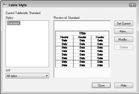
On the left side of the Table Style dialog box is a list of styles. From the List drop-down menu at the bottom, you can choose to display all styles or only styles that are in use in your drawing. To make a table style current, choose the style that you want and click Set Current.
Tip
An easier way to make a table style current is to choose the table style from the Table Style drop-down list in the Annotation panel (expanded) of the Home tab or the Tables panel on the Annotate tab. Choose your table style before you start to create a table. You can also import table styles from the DesignCenter. (For more information on the DesignCenter, see Chapter 26.)
To create a new style, click the New button. In the Create New Table Style dialog box, enter a Name in the New Style Name text box. From the Start With drop-down list, choose an existing table style as a basis for your new style. The new table style inherits the properties of this existing style so that you have to specify only the differences that you want. Then click Continue to open the New Table Style dialog box, as shown in Figure 13.19.
Note
You can select an existing table in the drawing as a starting point. In the Starting Table section, click the button to select a table in your drawing.
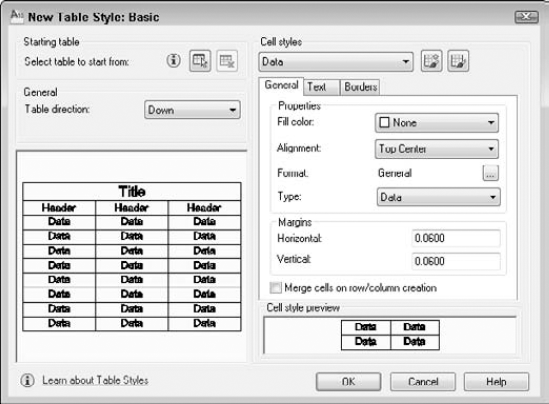
As you define your new table style, the preview panel shows you the results. You use the Cell Styles drop-down list to format data in the cells of the table, column headers, and the table's main title. Each category is one of the preexisting cell styles — data, header, and title — but you can create your own.
You use the three tabs to define general, text, and border formatting for each cell style. In this way, you format the entire table. The three cell styles are very similar, but have slightly different defaults. For example, the Title cell style has centered text and a larger height than the headers and data cells.
The General tab lets you define the following properties:
Fill color. Click the drop-down list to choose a color, or choose Select Color to open the Select Color dialog box. The default is None, which shows the background color of your drawing area.
Alignment. Use the Alignment drop-down list to specify the text alignment within each cell. For example, you might want to use Middle Center for the title and column headings, and Middle Left for the data cells.
Format. Click the Ellipsis button to open the Table Cell Format dialog box, where you can specify the data format. The default is general, which is good for text, but you can also format data for angles, currency, dates, decimal numbers, percentages, points, text, and whole numbers. Click the Additional Format button to open the Additional Format dialog box, where you can add a prefix or suffix, specify the number separator, and format zero suppression.
Type. Choose Data or Label. Use a label cell for a header or title. If you break a table into sections, then you can repeat label cells for each section. It's common to repeat headers when breaking a table.
Margins. The cell margins are the space between the text and the cell borders. The horizontal margins affect the left and right sides of the text, while the vertical margins affect the top and bottom of the text. Enter a value in the Horizontal and Vertical text boxes.
Check the Merge Cells on Row/Column Creation check box for titles that you want to span across an entire table.
The Text tab lets you specify properties for cells. You can choose a text style from the Text Style drop-down list or click the Ellipsis button to open the Text Style dialog box. (See the "Understanding Text Styles" section earlier in this chapter.)
You can also specify the text height (if the text style has a height of 0), a text color, and a text angle. The default text color is ByBlock, which means that the text color is the same as the actual table — which is a block. (I explain blocks and the ByBlock attribute in Chapter 18.) You can also choose ByLayer, which gives the text the properties of the current layer.
Use the Borders tab to specify the properties of the lines around the cells. Choose one of the border buttons to specify which borders you want to see. For example, for the data cells, if you choose Outside Borders, the data area of the table will not have any grid lines between the data cells, only around the outside of the cells.
Warning
If you inadvertently create a table style with only outside borders, you may not notice the absence of borders in your drawing, where grid lines show between the cells so that you can more easily fill in the table. Choose Preview on the Plot panel of the Output tab on the ribbon to see the final result more accurately.
Choose a border lineweight from the Lineweight drop-down list. For example, you may want a slightly thicker lineweight for the title cell. If you don't want to use continuous lines, then choose a linetype from the Linetype drop-down list. Then choose a color from the Color drop-down list. If you leave the ByBlock defaults, the lineweight, linetype, and color will match the layer of the table. Check Double Line to show two lines instead of one along the edge of the border for a cell. You control the spacing between the double lines with the value in the Spacing box.
Repeat the process of specifying general, text, and border properties for each of the three cell styles or your own styles. You access the styles from the Cell Styles drop-down list.
If you're creating your own cell styles, you specify which cell style goes where when you insert the table. (See Figure 13.17 earlier in this chapter.) Remember that you choose a cell style for the first row (usually the title), second row (usually the headers), and for all other rows (usually the data cells). Therefore, you would usually create three cell styles, one for each of these categories.
When you're done, click OK to return to the Table Style dialog box. Click Close. If you opened the Table Style dialog box from the Insert Table dialog box, then you're back in the Insert Table dialog box. If you opened the Table Style dialog box separately, open the Insert Table dialog box as described earlier in this chapter and choose the table style you want from the Table Style drop-down list. Either way, specify any other settings you want and insert the table.
You can add data to a table from three sources:
You can enter data by typing it.
You can link to external data — a Microsoft Office Excel worksheet or comma-delimited (CVS) file.
You can extract data from existing objects in the drawing (AutoCAD only).
You choose which method you want to use in the Insert Options section of the Insert Table dialog box. I discuss the first two methods in the next two sections.
Note
AutoCAD LT includes the ability to create a table from external data, but not from object data.
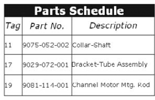
After you've placed a table, you can then enter data into the table. The cursor is automatically placed in the first cell, and you can just start typing. Press Tab to move to the next cell. Continue in this way until you have completed the table. Figure 13.20 shows an example of a table.
Tip
You can create a complete table on the fly by importing data from Microsoft Excel. Select the data in Excel and copy it to the Windows Clipboard. In AutoCAD, choose Home tab
You can insert a field into any cell in a table. Click a blank cell, right-click, and choose Insert
You can create tables that function like a spreadsheet. To enter a formula into a cell, follow these steps:
Select the cell.
Right-click and choose Insert
Choose one of the suboptions.
Sum. Adds rows or columns. At the
Select first corner of table cell range:prompt, pick inside the first cell. At theSelect second corner of table cell range:prompt, pick inside the last cell. You see the formula listed in the cell, for example, =Sum(C3:C5).Average. Averages rows or columns. At the
Select first corner of table cell range:prompt, pick inside the first cell. At theSelect second corner of table cell range:prompt, pick inside the last cell. You see the formula listed in the cell, for example, =Average(C3:C5).Count. Counts the number of cells in a row or column. At the
Select first corner of table cell range:prompt, pick inside the first cell. At theSelect second corner of table cell range:prompt, pick inside the last cell. You see the formula listed in the cell, for example, =Count(C3:C5).Cell. Displays the value of another cell. At the
Select table cell:prompt, select the cell that you want to display. You see the formula listed in the cell, for example, =C3.Equation. Lets you write your own equation. You just see an equal sign (=) in the cell. Enter the equation, for example =a3+b4.
Note
To create equations, you use the same conventions as for spreadsheets. For example, you use an asterisk (*) for multiplication, a slash (/) for division, a caret (^) for powers, and
sqrtfor a square root.You also see row headings (1, 2, 3, and so on) and column headings (A, B, C, and so on), so that you can easily determine any cell's address.
Press Enter to place the value of the formula.
Tip
You can auto-fill data like you can in Excel. This makes it easy to copy data along a row or column and to automatically create incremental data, such as consecutive numbers. To auto-fill cell data, click in a cell that you've already filled with a value. Click and drag the cyan (turquoise) diamond to the desired cell and click. To auto-fill incremental data, such as consecutive numbers, drag across two cells that already have incremental data. For example, if you typed 1 and 2, drag across those cells. Then click and drag the cyan diamond to the desired cell and click. Before the final click, a tooltip shows you what results to expect.
You can create a table that links to external data that was created in Microsoft Excel or that is in comma-delimited (CSV) format. The link maintains its connection, so that if you change the spreadsheet, the table in your drawing also changes. You also have the option to change the external data from within AutoCAD.
Note
In Chapter 20, I cover the external database connectivity feature. While this feature also allows you to connect to Microsoft Access databases and other types of databases, it's more complicated to use.
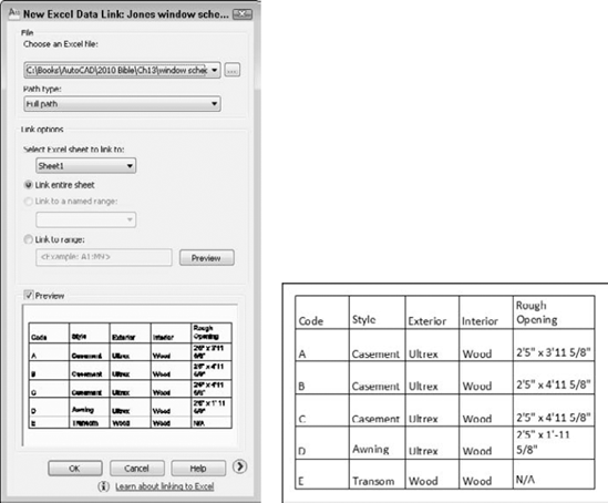
To create a linked table, you first need an Excel or CSV file. Make sure that you know the file's name and location. Then choose Home tab
The New Excel Data Link dialog box opens. Click the Ellipsis button at the right to choose an Excel file. When you click Open, you return to the New Excel Data Link dialog box, with your data link listed, as shown on the left in Figure 13.21.
In the Link Options section, you can choose which sheet you want to use, and you can link to a named range (you can name ranges of cells in Excel) or you can specify a range, such as A1:H20. Click OK to return to the Select a Data Link dialog box, where your data link is now listed and highlighted. Click OK to return to the Insert Table dialog box. You should see your table in the Preview box.
Note
You can click the More Options arrow at the lower-right corner of the New/Modify Excel Data Link dialog box to convert cell data to text, to turn off the ability to save changes that you make in AutoCAD back to the source spreadsheet, and to control cell formatting. You can choose whether or not to use Excel formatting and keep the table updated to the formatting in the Excel file.
Click OK one more time and specify an insertion point to insert the table into your drawing. You may have to resize the table to avoid unwanted word wrapping in the cells. (See the upcoming section, "Modifying a table," for instructions.) Figure 13.21 shows the result on the right.
When you create a linked table, it's locked to prevent changes; this makes sense, because the content should come from the Excel spreadsheet. However, you can unlock it and make changes; you can save these changes back to the spreadsheet to keep the two data sources the same. To unlock data (both content and formatting), select one or more cells, right-click, and choose Locking
After changing the data, right-click and then choose Data Links
You can create a table that contains information about the objects in your drawing. For example, you might want to display the number of window blocks and their location. If a circle represents trees and bushes in a landscaping plan, you could list the number of circles and their layer; perhaps you have a tree and a bush layer. You can extract data from all objects, not just blocks. For information about extracting data from blocks using attributes, see Chapter 18.
To create a table from object data, choose Home tab
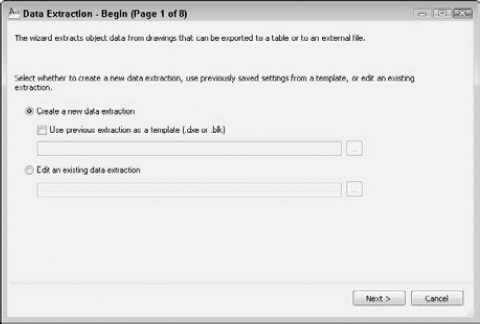
Figure 13.22. The Data Extraction Wizard guides you through the process of creating a table from object data.
Choose to create a new extraction or edit an existing one. If you want to create a new extraction, you can use one of two types of files as a template to use settings you've specified previously:
DXE. When you create a data extraction table, AutoCAD creates a DXE file that contains settings for the extraction.
BLK. When you extract attribute information from blocks, you can save a BLK file, which is a template that defines the settings for the extraction.
The following explains how to create a new data extraction without a template. Choose Create a New Data Extraction and click Next. The Save Data Extraction As dialog box opens, so you can save a DXE file; this is the file that you can use in the future as a template. Choose a name and location and click Save.
On the Define Data Source (Page 2 of 8) page of the wizard, you define which objects you want to include and where they come from. You can use a Sheet Set, which is a collection of drawings (covered in Chapter 26) or choose any drawings that you want. The Drawing Files and Folders box lists the drawings and their locations. If you want to use objects from other drawings, click Add Drawings. To add all the drawings in a folder, click Add Folder.
If you choose multiple drawings, you create a table from all the objects in those drawings. If you want to select specific objects, you can do so only in the current drawing. In that case, choose the Select Objects in the Current Drawing option. The following assumes that you are selecting objects in the current drawing.
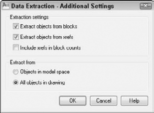
Click the Settings button to open the Data Extraction - Additional Settings dialog box, shown in Figure 13.23, where you define which types of objects you want to include. These settings are particularly important if you are extracting data from entire drawings (rather than selecting objects) and you have blocks or xrefs in those drawings. (I cover blocks in Chapter 18 and xrefs in Chapter 19.) Choose whether you want to extract data from blocks and xrefs and whether to include xrefs in the block count. You can also choose whether to include objects only in model space or all objects in the drawing, meaning also objects in layouts. (See Chapter 17 for coverage of layouts.)
The Select Objects page shows the objects you've selected. You can choose to display only blocks or only non-blocks, instead of the default, which is to display all object types. If you're interested in blocks, you can choose to include only blocks with attributes. Finally, you can choose to display objects that are currently in use because some blocks may be defined but not inserted into the drawing. (See Chapter 18 for information about attributes.) Then click Next.
On the Select Properties page, you specify which properties of the objects you want to include. The properties come in 10 categories:
3D Visualization. Includes materials assigned to objects. (See Chapter 22.)
Attribute. Includes blocks and dynamic blocks with attributes. (See Chapter 18.)
Drawing. File-related information including the author, date created, dated accessed, location, name, size, total editing time, and so on.
Dynamic blocks. Properties of dynamic blocks. (See Chapter 18.)
General. Includes color, layer, linetype, linetype scale, plot style, thickness, and hyperlink.
Geometry. Depending on the type of object, can include area; center; circumference; diameter; length; radius; start angle; total angle; delta (change) in X, Y, and Z; start of X, Y, and Z coordinates; and so on.
Misc. Includes closed (or open).
Pattern. Includes hatch pattern properties, which I cover in Chapter 16.
Table. Includes table properties.
Text. Includes single or multiline text properties.
For each category, you can choose which property you want to include by checking the check boxes. As you can see, your choices depend on why you're extracting the data. In some cases, you may want drawing information for archiving purposes; in other cases, you may be interested only in geometry data. When you're done, click Next.
On the Refine Data page, you can reorder and sort columns, filter the results, combine identical rows, specify if you want a count or a name column, add formulas, and include external data. Click on a column and right-click for numerous options, including the ability to rename and hide columns. Click on any column to sort by that column, and click again to reverse the sorting order. Right-click and choose Filter Options to open the Filter dialog box, which is similar to the Quick Select feature (described in Chapter 10), but has fewer options.
Tip
When extracting data, you can add formulas such as totals to a column. Right-click the column and choose Insert Totals Footer. You can choose Sum, Max, Min, or Average. You can also create a new column from data in other columns. Right-click any column and choose Insert Formula Column. Use the Insert Formula Column dialog box to specify the formula. Click OK.
Click the Full Preview button to see what the table will look like in a new window; then click the window's Close button to return to the wizard and click Next.
On the Choose Output page, you can choose to create a table and insert it into a drawing, output the data to an external file (XLS, CSV, MDB, or TXT), or both. If you choose to create an external file, click the Ellipsis button to browse to a location and give the file a name. Then click Next.
If you chose to create a table, you now choose a table style or manually set up the table. Then click Next. The Finish page explains that you need to specify an insertion point for the table and that the external file you requested (if any) will be created when you click the Finish button. Click the Finish button and you're done.
You may need to change the data in a table, or you may want to change the way the table looks. Either way, you can modify a table easily. However, you need to know some of the techniques involved, because tables in AutoCAD and AutoCAD LT are a little different from tables in your word processor.
Changing the text of a table is like changing any multiline text. Double-click the text inside a table, being careful not to double-click the grid lines. The In-Place Text Editor opens. You can use any of the techniques for editing text that I discuss in the "Editing paragraph text" section earlier in this chapter. You can change the properties of the text so that they don't match the table style. For example, you can change the height or font of the text.
You can also change properties of the table itself. Open the Properties palette (Ctrl+1) and select the table. Here, you can modify any conceivable table property, including its layer, its color, the number of rows or columns, or any of its style properties. If you want to revert to old-fashioned lines, you can explode the table. Of course, you can no longer edit the table as a table anymore; you just have lines and text.
To select the entire table, click any gridline of the table. You see grips at the corners of the table and at several other cell junctions. To understand editing tables with grips, imagine that the left side of the table is the stable side, while the right side of the table is the flexible side. The top-left grip is the base point for the entire table. You can do the following edits with grips:
Upper-right grip. Stretches the table horizontally. As you change the width of the table, the columns also stretch proportionally.
Lower-left grip. Stretches the table vertically. As you change the height of the table, the rows also stretch proportionally.
Lower-right grip. Stretches the table both vertically and horizontally. The columns and rows adjust proportionally.
Top-of-column grip. Adjusts the width of the column to the left or right of the grip. The entire table adjusts accordingly. If you press Ctrl while moving a column grip, the adjacent columns adjust, but the width of the table remains unchanged.
If you select the table and right-click, then you can use the shortcut menu to make additional changes to the table. For example, you can size columns or rows equally or remove property overrides. If you make a change to a cell, such as the cell's alignment or color, you can use the Remove All Property Overrides item on the shortcut menu to change the cell's properties back to match the rest of the table.
To select a cell, click inside that cell. You can also click a column or row header, or drag across several cells to select them. The Table Cell tab appears on the ribbon. (If you're using the AutoCAD Classic workspace, you'll see a Table toolbar.)
In the Rows panel, the following items are available:
Insert Above. Inserts a row above the selected cell or row.
Insert Below. Inserts a row below the selected cell or row.
Delete Row(s). Deletes the selected row or the row of the selected cell.
In the Columns panel, the following items are available:
Insert Left. Inserts a column to the left of the selected cell or row.
Insert Right. Inserts a column to the right of the selected cell or row.
Delete Column(s). Deletes the selected column or the column of the selected cell.
In the Merge panel, you have the following options:
Merge Cells. Merges selected cells. You need to select multiple cells. (See techniques for doing so after this list.) The suboptions let you merge by row or by column. By merging cells, you can create complex table structures.
Unmerge Cells. Unmerges selected cells that you previously merged.
In the Cell Styles panels, the following options are available:
Match Cell. Matches cell properties. At the
Select destination cell:prompt on the command line, pick another cell that you want to have the same properties. The prompt repeats until you press Enter.Cell Alignment. Changes the alignment of the text in the cell, using the standard text-alignment options available for multiline text.
Cell Styles. Enables you to choose a cell style for the selected cell from the drop-down list. You can also choose to create a new cell style or manage existing cell styles.
Background Fill. Sets a background color for the selected cell.
Edit Borders. Opens the Cell Border Properties dialog box, where you can specify border properties for that individual cell.
The Cell Format panel has two options:
Locking. Locks or unlocks the format and/or the data of the selection. Text from external links or data extraction is locked by default.
Data Format. Allows you to choose a format from a drop-down list. Choose Custom Table Cell Format to open the Table Cell Format dialog box, where you can change the data type and format.
The Insert panel has the following options:
Block. Opens the Insert a Block in a Table Cell dialog box, where you can select the block that you want to insert, specify the block's alignment in the cell, and set its scale and rotation angle. If you select the AutoFit check box, the block is automatically scaled to fit the table cell.
Field. Lets you insert or edit a field. I discuss fields in the next section of this chapter.
Formula. Lets you insert a formula, as explained in the "Entering data into a table" section earlier in this chapter.
Manage Cell Contents. Applies when you have more than one block in a cell. The Manage Cell Content dialog box opens, where you can change the order of the blocks and change the way they're laid out.
In the Data panel, the following options are available:
Link Cell. Enables you to link the selected cell to an Excel spreadsheet. For more information, see the section "Linking to external data" earlier in this chapter.
Download from Source. Updates links, if available, from an external spreadsheet, in case that spreadsheet has changed.
You can access some additional options by right-clicking with a cell or cells selected:
Remove All Property Overrides. Removes any formatting that you applied to the selected cell.
Edit Text. Opens the In-Place Text Editor so that you can edit text.
Delete All Contents. Deletes any text or block in the current cell.
Columns
Size Equally. Makes two or more columns that you select equally wide.Rows
Size Equally. Makes all your rows an equal height.Properties. Opens the Properties palette so that you can change the cell's properties.
Quick Properties. Opens the Quick Properties palette so that you can change the cell's properties.
When you edit a table, column and row headers appear so that you can easily refer to cells in your formulas. You can change the background color of these headers to make the text clearer. Select a table, right-click, and choose Table Indicator Color. You can then choose a color in the Select Color dialog box.
You can select multiple cells and apply changes to those cells. To select multiple cells, use one of the following techniques:
Click a row or column header to select an entire row or column.
Click inside one cell and drag over the other cells that you want to select. Release the mouse button at the last cell.
Click inside one cell, hold down Shift, and click inside the last cell that you want to select.
Tip
To enter the same text in multiple cells, select the cells. Then open the Properties palette and enter the text in the Contents item. The text appears in all the selected cells.
You can export a table to comma-delimited (.csv) format. You can then open the table data with a database or spreadsheet program. To export a table, follow these steps:
Select the table.
Right-click and choose Export.
In the Export Data dialog box, choose a name and location for the file.
Click Save.
Sometimes you need to fit a table into a tight space; to do so, you might want to break up the table into two or more sections.
Breaking a table is easy, but you can also access a number of settings to fine-tune how it works. To break a table, click it once to select it. Then drag the cyan down arrow, located at the bottom of the table, upward to the point where you want the table to break (see Figure 13.24), and click.
To adjust breaking settings, open the Properties palette. In the Table Breaks section, you can set the direction of subsequent sections, repeat top labels, and repeat bottom labels. You can also manually set the position of sections, individually set the height of subsequent sections (otherwise, they're the same size as the first section), and set the spacing between the sections. In this example, I chose to repeat top labels; you can see the result in Figure 13.25.
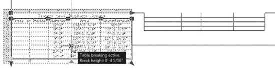
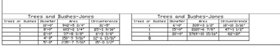
Note
The drawing used in the following exercise on creating tables, ab13-c.dwg, is in the Drawing folder on the DVD.
STEPS: Creating Tables
Open
ab13-c.dwgfrom the DVD. This is the same drawing used in the previous exercise.Save the file as
ab13-06.dwgin yourAutoCAD Biblefolder.

In the Table Style dialog box, click New. In the Create New Table Style dialog box, enter Acreage Schedule in the New Style Name text box. The Start With text box should read
Standard. Click Continue. The New Table Style dialog box opens.
On the General tab, you want to set the numbers in the table to be right-aligned, so choose Middle Right from the Alignment drop-down list. In the Cell Margins section, change both the Horizontal and Vertical text box values to 5.
Click the Text tab. From the Text Style drop-down list, choose
ROMANS. In the Text Height text box, enter 12.5.To format the column headers, choose Header from the Cell Style drop-down list. Again, click the Create a New Cell Style button, name the cell style Plat Header, and click Continue. On the General tab, leave the alignment as Middle Center, but change the cell margins to 5. On the Text tab, again set the Text Style to
ROMANSand the Text Height to 12.5.Choose Title from the Cell Style drop-down list. Create a new cell style named Plat Title. Make the following changes:
General tab. Change the cell margins to 5. From the Fill Color drop-down list, choose
Blue.Text tab. Choose
ROMANT(for a different look). Change the Text Height to 13.5 to make the title text bigger than the rest of the table text. Click the Text Color drop-down list and choose Select Color. From the Select Color dialog box, choose the light gray color (254) on the Index Color tab. Click OK to return to the New Table Style dialog box.Borders tab. From the Color drop-down list, choose Blue to match the fill. Click the All Borders button.
Click OK to return to the Table Style dialog box. Then click Close to return to the Insert Table dialog box.
In the Insertion Behavior section of the dialog box, make sure that the insertion behavior is set to
Specify insertion point. In the Columns & Row Settings section, set the number of columns to 2 and the column width to 100. Set the number of data rows to 5. The row height should be 1 (which means one row high).In the Set Cell Styles section, set the First Row Cell Style to Plat Titles, set Second Row Cell Style to Plat Header, and set All Other Row Cell Styles to Plat Data. Then click OK.
In your drawing, pick an insertion point anywhere in the lower-right area of the drawing. The In-Place Text Editor opens. Because you need to zoom in first, click anywhere outside the editor and do a ZOOM Window around the table. Then double-click the table to open the In-Place Text Editor again, with the cursor in the title cell.
Tip
To zoom in without exiting the In-Place Text Editor, you can use the wheel of your mouse (if you have one). I explain how to zoom with the mouse wheel in Chapter 8.
Complete the data for the four plats, shown in Figure 13.26, pressing Tab to go from cell to cell.
Type Total in the last row. Right-click the cell and choose Alignment
Click anywhere outside the In-Place Text Editor and then click the lower-right cell to select it. Right-click the cell and choose Insert
At the
Select first corner of table cell range:prompt, click anywhere inside cell B3. At theSelect second corner of table cell range:prompt, click anywhere inside cell B6. Press Enter. Your table should look like Figure 13.26.Save your drawing.
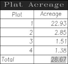
Most drawings contain information about the drawing, such as the last date it was revised, the person who saved the drawing, or the sheet number in a sheet set. Draft plots often contain additional information, such as the time and drawing name. You may also want to insert information about drawing objects, such as the area or circumference of a circle. Fields store information and allow you to insert it into a drawing. You can also place fields in block attributes, which I discuss in Chapter 18. When your drawing changes, you can update the fields to keep them current. You can insert fields anywhere that you might normally use text. As you start using fields, you'll think of many uses for them. You can format the text of a field in the same way that you format any multiline text.
To create a new field as a multiline text object, you can use two methods:
Choose Insert tab
Open the In-Place Text Editor or any other text box where you can enter text, right-click in the editor or text box, and choose Insert Field from the shortcut menu.
Whichever method you use, the Field dialog box opens, as shown in Figure 13.27.
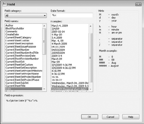
The Field dialog box offers a huge variety of fields. To give you an idea of the possibilities, here are the available categories of fields:
Date & Time. Offers various formats for inserting dates and times.
Document. Relates to data that you complete in the Properties dialog box. (Choose Application Button
Linked. Creates a field from a hyperlink.
Objects. Offers properties relating to block attributes, formulas in tables, named objects (such as named views, layers, blocks, and so on), and objects (any drawing object that you select).
Other. Displays values of AutoLISP variables (AutoCAD Only) and system variables.
Plot. Displays plot-related information such as scale, sheet size, and orientation.
SheetSet. Displays values relating to sheet sets. (Sheet sets are available only in AutoCAD; I cover them in Chapter 26.)
Note that there are two date-related fields. The CreateDate field creates a date based on the current date. This field does not change if you open the drawing on a future date. For example, you can use this field to show the last time a drawing was updated. The Date field always shows the current date.
To insert a field, follow these steps:
Choose a field category from the Field Category drop-down list. You can use the All category to display all the fields. The other categories help you to filter the fields.
From the Field Names list, choose the field that you want to use.
Depending on the field that you choose, you can usually select a format or example for the field. For example, you can choose a date format (such as m/d/yyyy) or a text format (such as title case).
Click OK.
If you opened the Field dialog box by choosing Insert tab
If you started the MTEXT command first, the value of the field appears in the In-Place Text Editor. Click outside the editor to place the text, and close the editor.
By default, fields appear in your drawing with a gray background. This background doesn't plot. If you want, you can remove the background by choosing Application Button
Figure 13.28 shows an example of a titleblock that uses fields.
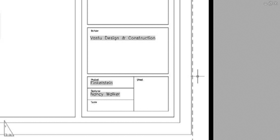
To edit a field, double-click the field's text to open the In-Place Text Editor. Select the text, right-click, and choose Edit field. The Field dialog box opens. You edit a field in the same way that you define the field originally. When you're done, click OK. The field is reevaluated immediately. Close the In-Place Text Editor to place the edited field.
By default, a field is evaluated and updated, if necessary, whenever you open, save, plot, eTransmit, or regenerate a drawing. (See Chapter 28 for information on eTransmitting a drawing.) You can change when AutoCAD updates a field by choosing Application Button
You can manually update a field if you want. For example, you may have an object field that displays the radius of a circle. If you resize the circle, you probably want to update the field.
To update a field, double-click the field to open the In-Place Text Editor. Select the text, right-click, and choose Update Field. Close the In-Place Text Editor to return to your drawing. Another method is to select the field and choose Insert tab
You can convert a field to text. Open the In-Place Text Editor. Select the text in the field, right-click, and choose Convert Field to Text.
What happens to fields when you save a 2005 or later drawing to an earlier release of AutoCAD? The fields display as their last value in the newer drawing but are not updated.
Note
The drawing used in the following exercise on using fields, ab13-d.dwg, is in the Drawing folder on the DVD.
Open
ab13-d.dwgfrom your DVD. Save the file asab13-07.dwgin yourAutoCAD Biblefolder. This drawing is zoomed in on the titleblock.To set some of the drawing properties, choose Application Button
On the Custom tab, click Add. Enter the following two fields and values:
Drafter
Enter your initialsDwg No SK-1972Click OK to return to your drawing.
Choose Home tab
From the Field Category drop-down list, choose Document. From the Field Names list, choose Title. From the Format list, choose Title Case. Click OK. Click anywhere outside the In-Place Text Editor to place the field.
Again start the MTEXT command. Pick two boundary points within the Dwg No box of the titleblock. In the In-Place Text Editor, right-click and choose Insert Field to open the Field dialog box.
From the Field Names list, choose Dwg No. Click OK. Click anywhere outside the In-Place Text Editor to place the field.
Repeat the MTEXT command. Pick two boundary points within the Date box of the titleblock. In the In-Place Text Editor, right-click and choose Insert Field.
From the Field Category drop-down list, choose Date & Time. From the Field Names list, choose CreateDate. From the Format list, choose M/d/yy. Click OK. Click anywhere outside the In-Place Text Editor to place the field.
If necessary, move the text so that it fits better in the titleblock. Save your drawing. The titleblock should look like Figure 13.29.
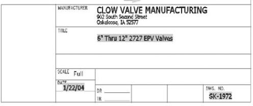
Text is a complex object type that increases your drawing size and adds redraw and regeneration time. TrueType fonts can have an impact on how long it takes to open and save a file. The techniques described in this section help you to manage text and improve performance while editing your drawing.
The QTEXT command replaces all text with rectangles that approximate the placement of the original text. All text objects, including dimensions, attributes, and tolerances, are affected. To use QTEXT, type qtext
AutoCAD and AutoCAD LT fonts are simpler than TrueType fonts, and offer a range of complexity. The simplest font is txt.shx. You can easily define a text style by using an AutoCAD or AutoCAD LT font and then change the font to something nicer just before plotting. Be aware that the text may take up more or less space than before.
When your drawing cannot find the specified font, it uses an alternate font. This may happen if you receive a drawing from someone else that uses a custom or third-party font that you don't have. You can specify the alternate font by choosing Application Menu
You can further control the fonts used in your drawing by customizing the Font Mapping File, acad.fmp (or acadlt.fmp). The format is current_font; font_to_substitute. (You need to use the actual filenames of the fonts.) To substitute a simpler font for the Arial Black font, you can add the following line:
Ariblk.ttf;simplex.shx
To find the Windows TrueType fonts, look in the Fonts subfolder of your Windows folder.
Note
To find acad.fmp (or acadlt.fmp), choose Application Button
Freezing text layers can reduce regeneration time dramatically; this is a good reason to give text its own layer. Don't forget to freeze dimension text, as well. Dimensions (see Chapter 14) are usually placed on a separate layer.
When you mirror sections of your drawing that include text, you usually don't want any backward text (unless you're Alice going through the looking glass). The MIRRTEXT system variable controls whether text is mirrored or retains its normal orientation. The default value for MIRRTEXT is off, so mirrored text is not backward. The text is copied to the mirrored location, but reads from left to right (if that's the direction of the language that you're using).
If you do want to mirror the text, type mirrtext
Note
Express Tools has a number of text routines that you may find very helpful. Table 13.2 lists these tools.
Table 13.2. Express Tools for Text
Command | Ribbon Location | Description |
|---|---|---|
RTEXT | Express Tools tab | Displays text from an outside file. You can specify the text style, height, and rotation. Use RTEDIT on the command line to edit remote text. |
TEXTFIT | Express Tools tab | Stretches or shrinks Text objects (but not MText) to fit between two points. |
TEXTMASK | Express Tools tab | Creates a wipeout, 3D face, or 2D solid object behind the text, with a little extra space around the text. You can use this to make text on top of a hatch more legible. |
TEXTUNMASK | Express Tools tab | Removes a text mask. |
TXTEXP | Express Tools tab | Transforms Text or Mtext into geometrical shapes. |
TXT2MTXT | Express Tools tab | Converts Text objects to Mtext objects. |
ARCTEXT | Express Tools tab | Aligns text along an arc. |
TORIENT | Express Tools tab | Rotates multiple text, Mtext, and attribute definitions to a specified angle without moving them, or aligns them so that they're horizontal or right-side up for easy reading. |
TCIRCLE | Express Tools tab | Encloses selected Text or Mtext inside a circle, a slot (a rectangle, but with arcs at each end), or a rectangle. |
TCOUNT | Express Tools tab | Numbers lines of text by adding a prefix or suffix, or by overwriting the text. |
TCASE | Express Tools tab | Offers the following ways to change the case of text: uppercase, lowercase, sentence case, title case, and toggle case. |
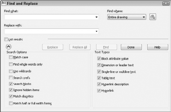
Here's how to use the Find and Replace dialog box:
If the text you want to find isn't in the Find What text box, enter it now. Use the drop-down list to choose recently used text strings.
Tip
When finding text, you can use wildcard characters such as * (for any number of characters), ? (for any single character), and # (for any numeric character) in the Find Text String text box.
If you want to replace the text that you find with new text, type it in the Replace With text box. This box also includes a drop-down list of recently used text strings.
If you want to limit or expand the scope of your search, use the Find Where drop-down list. If you selected objects before starting the FIND command, this drop-down list displays Selected Objects. You can choose Entire Drawing from this list. You can also click the Select Objects button to return to your drawing and select objects. The FIND command then limits its search to selected objects. Choose Current Space/Layout to look for the text string only on the Model or layout tab that is current.
Click the More Options down arrow to expand the dialog box and specify the type of text that FIND will search in the Text Types list. By default, it searches all types of text, including attributes (Chapter 18), dimensions (Chapter 14), tables, and hyperlinks (Chapter 18). The command can find text in fields, as well.
In the Search Options list, you can also choose the Match Case and Find Whole Words Only options. You can also choose to use wildcards, search xrefs and blocks, ignore hidden items, match diacritics (such as accent marks), and match half/full width forms (for East Asian languages).
Note
Hidden items are text on frozen or off layers, text in block attributes using invisible mode, and text in dynamic block visibility states.
Click Find or Find Next to find the next instance of the text string. The drawing zooms in to the text and moves the dialog box so that it doesn't cover up the text.
Click Replace to replace the text string with the replacement text. Click Replace All to replace all instances of the text string with the replacement text.
Check the List Results check box to list the results that have been found.
After you're finished, click Done to close the dialog box.
If you take pride in the accuracy of your drawings, you might as well make sure that the text is spelled correctly. You can use the SPELL command to check your spelling. The spelling checker acts just like the one in your word processor.
If you want, you can select some objects first. Choose Annotate tab
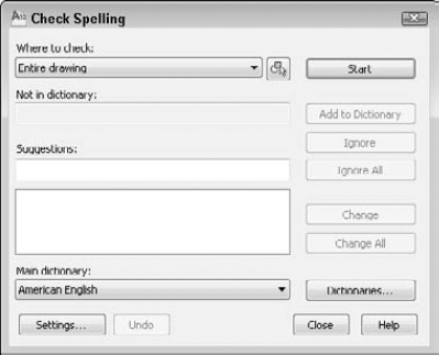
From the Where to Check drop-down list, choose Entire Drawing, Current Space/Layout, or Selected Objects. (I cover layouts in Chapter 17.) Click the Settings button to open the Check Spelling Settings dialog box, where you can choose if you want to include dimension text (see Chapter 14), block attributes (see Chapter 18), or external references (see Chapter 19). You can also ignore capitalized words (proper names), words that include numbers, uppercase words, words with mixed cases, such as EllenFinkelstein.com, and words containing punctuation. Click OK when you're done.
In the Check Spelling dialog box, click Start. When the first misspelled word appears in the Not in Dictionary text box, you have the following options:
Add to Dictionary. Choose Add to Dictionary to add the word to the dictionary. The word will not appear again as misspelled.
Ignore. Choose Ignore to ignore the current instance of this word only.
Ignore All. Choose Ignore All to ignore all instances of this word.
Change. Select the suggested word that you want, and choose Change to change the current instance of the word to the suggested word that you selected.
Change All. Select the suggested word that you want, and choose Change All to change all instances of the word to the suggested word that you selected.
Notice that the drawing zooms in and highlights each word. The command automatically moves from word to word until you see the message Spelling Check Complete. Click OK and click Close to close the Check Spelling dialog box.
When you edit text, the Text Editor tab appears, which contains a Spell Check panel. Click the dialog box launcher arrow at the right end of the panel's title bar to open the Check Spelling Settings dialog box, where you can specify which type of text you want to include in spell checks and set options for ignoring certain types of text, such as capitalized words. You can change the main and custom spelling dictionaries. To change the main dictionary, choose one from the Main Dictionary drop-down list; these are dictionaries in different languages. Choose Dictionaries from the Check Spelling dialog box to open the Dictionaries dialog box, as shown in Figure 13.32.
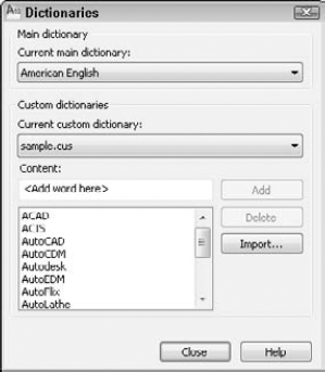
The custom dictionary is the dictionary that you add to when you click Add in the Dictionaries dialog box. It is a simple text file that includes words that you have added during spelling checks, as well as a list of drawing-related words that come with the file. You can add words to the custom dictionary by typing them in the Content text box and clicking Add.
Tip
Another way to edit the custom dictionary is to open the file directly with a text editor. The custom dictionary is called sample.cus. To find sample.cus, choose Application Button
You can use a different custom dictionary. For example, it can be useful to use the same dictionary in your drawing as you use in your word processor. Here's how to use the Microsoft Word dictionary:
Find Word's custom dictionary. If necessary, choose Start
As explained in the previous Tip, find the location of
sample.cus. Use Windows Explorer to copycustom.dicto that folder. You can hold down Ctrl as you drag it from one folder to another or use the right mouse button to click the file, choose Copy, and then paste it in its new location.Click
custom.dicto highlight it. Click it again and change its filename extension to.cus. Press Enter. Windows asks you whether you are sure you want to do this. Click Yes.Click Dictionaries in the Check Spelling dialog box to open the Dictionaries dialog box. From the Current Custom Dictionary drop-down list, choose Manage Custom Dictionaries, and click Add. Find the file, and click Open.
Click Close three times to return to your drawing.
In this chapter, you learned how to create, edit, and manage text. You read about:
Using DTEXT and TEXT to create single-line text
Editing single-line text
Creating text styles to control the formatting of your text, including creating annotative text styles
Utilizing MTEXT for creating and editing paragraph text, including using the In-Place Text Editor
Importing text
Creating tables to clearly display data, including linking to external data and extracting object data
Using fields to automate the insertion of text
Managing text for the fastest display
Finding and replacing text
Checking spelling in your drawing and editing the spelling dictionaries
In the next chapter, you read about how to create dimensions.