
Gas Turbine Fuel Systems and Fuels
Abstract
The basics of a gas turbine fuel system are similar for all turbines. The most common fuels are natural gas, LNG (liquid natural gas), and light diesel. With appropriate design changes, the gas turbine has proved to be capable of handling residual oil, pulverized coal, syngas from coal and various low BTU fluids, both liquid and gas, that may be waste streams of petrochemical processes or, for instance, gas from a steel (or other industry) blast furnace. Handling low BTU fuel can be a tricky operation, requiring long test periods and a willingness to trade the savings in fuel costs with the loss of turbine availability during initial prototype full load tests. This chapter covers gas turbine fuel systems and includes a case study (Case 5) on blast furnace gas in a combined cycle power plant (CCPP).
Keywords
Gas turbine fuel systems; syngas; coal; oil types; fuel strategy; combustion process; fuel treatment
“All truths are easy to understand once they are discovered, the point is to discover them.”
—Plato
The basics1 of a gas turbine fuel system are similar for all turbines. The most common fuels are natural gas, LNG (liquid natural gas), and light diesel. With appropriate design changes, the gas turbine has proved to be capable of handling residual oil, pulverized coal, syngas from coal and various low BTU fluids, both liquid and gas, that may be waste streams of petrochemical processes or for instance gas from a steel (or other industry) blast furnace. Handling low BTU fuel can be a tricky operation, requiring long test periods and a willingness to trade the savings in fuel costs with the loss of turbine availability during initial prototype full load tests.
This chapter includes a case study (case 5) on blast furnace gas in a combined cycle power plant (CCPP). Chapter 4 has a case study that describes some of the combustion chamber component design changes required to handle low BTU waste gas.
As the world continues to industrialize, the applications that use waste fluids as low BTU fuel are likely to increase. Residence time in the combustion chamber is one factor that helps facilitate this economy of resources.
In general, a gas turbine fuel system consists of:
• A fuel delivery system that includes pump(s), valves, piping, and other accessories
• Fuel nozzles, simplex (one jet for one fuel type or phase, usually gas), duplex (gas or liquid), dual fuel (gas and liquid at the same time), or triplex (three fuel types)
If the fuel in question is nonconventional, for instance, heavy residual fuel, the fuel system also embodies
• Fuel additives (to deal with vanadium)
• Fuel washing (to deal with sodium and potassium salts)
• Modifications to the fuel delivery system (such as preheating to move more viscous fuels more easily) and fuel nozzles
If the fuel is pulverized coal, biomass (agricultural or otherwise), peat or black liquor from pulp and paper manufacture, waste hydrocarbons from plastics manufacture, flue gas from steel production, or a myriad of expanding options, the individual system has design refinements to suit those fuels. These design modifications may incorporate higher residence times in the combustion chamber (to allow for lower BTU values) as well as hardware changes.
Fuel efficiency is a key ingredient of gas turbine and gas turbine systems marketing, especially if the fuel is an optimum choice fuel, such as natural gas, which burns cleaner than other fossil fuels. All other aspects of gas turbine design, including aerodynamic efficiency and losses (aerodynamic or otherwise) affect fuel efficiency. As is indicated in the chapter on calculations, designers struggle for every fraction of an efficiency point (see also Chapter 14, The Business of Gas Turbines, and Chapter 18, Future Trends in the Gas Turbine Industry). How much they gain depends heavily on the type(s) of fuel in use and their delivery system.
What follows is the description of the basic fuel system of a gas turbine. The specific fuel system referred to belongs to a Rolls Royce aeroengine (the Gem 60). However, the basic components and fuel flow depicted are similar in most gas turbine engines, although design nuances and refinements vary greatly among OEMs. Note also that a turboprop application is similar to a land-based mechanical drive application.
Basic Gas Turbine Fuel System2
The functions of the fuel system are to provide the engine with fuel in a form suitable for combustion and to control the flow to the required quantity necessary for easy starting, acceleration and stable running, at all engine operating conditions. To do this, one or more fuel pumps are used to deliver the fuel to the fuel spray nozzles, which inject it into the combustion system in the form of an atomized spray. Because the flow rate must vary according to the amount of air passing through the engine to maintain a constant selected engine speed or pressure ratio, the controlling devices are fully automatic with the exception of engine power selection, which is achieved by a manual throttle or power lever. A fuel shutoff valve (cock) control lever is also used to stop the engine, although in some instances these two manual controls are combined for single-lever operation.
It is also necessary to have automatic safety controls that prevent the engine gas temperature, compressor delivery pressure, and the rotating assembly speed from exceeding their maximum limitations.
With the turbo-propeller engine, changes in propeller speed and pitch have to be taken into account due to their effect on the power output of the engine. Thus, it is usual to interconnect the throttle lever and propeller controller unit, for by so doing the correct relationship between fuel flow and airflow is maintained at all engine speeds and the pilot is given single-lever control of the engine. Although the maximum speed of the engine is normally determined by the propeller speed controller, overspeeding is ultimately prevented by a governor in the fuel system.
The fuel system often provides for ancillary functions, such as oil cooling and the hydraulic control of various engine control systems; for example, compressor airflow control.
Manual and Automatic Control
The control of power or thrust of the gas turbine engine is effected by regulating the quantity of fuel injected into the combustion system. When a higher thrust is required, the throttle is opened and the pressure to the fuel spray nozzles increases due to the greater fuel flow. This has the effect of increasing the gas temperature, which in turn increases the acceleration of the gases through the turbine to give a higher engine speed and a correspondingly greater airflow, consequently producing an increase in engine thrust.
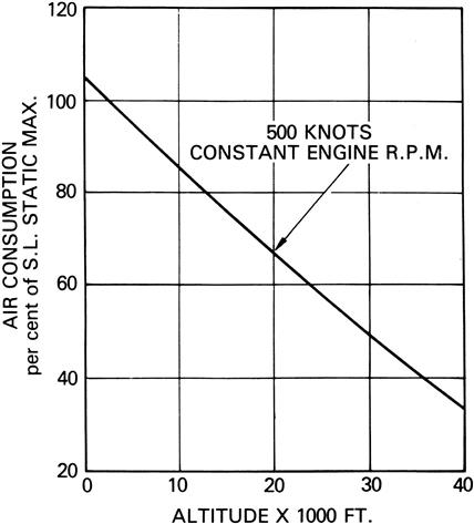
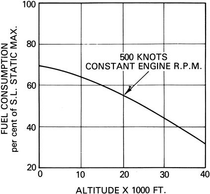
This relationship between the airflow induced through the engine and the fuel supplied is, however, complicated by changes in altitude, air temperature and aircraft speed. These variables change the density of the air at the engine intake and consequently the mass of air induced through the engine. A typical change of airflow with altitude is shown in Figure 7–1. To meet this change in airflow a similar change in fuel flow (Figure 7–2) must occur, otherwise the ratio of airflow to fuel flow will change and will increase or decrease the engine speed from that originally selected by the throttle lever position.
Described here are five representative systems of automatic fuel control; these are the pressure control and flow control systems, which are hydro-mechanical, and the acceleration and speed control and pressure ratio control systems, which are mechanical. With the exception of the pressure ratio control system, which uses a gear-type pump, all the systems use a variable-stroke, multi-plunger type fuel pump to supply the fuel to the spray nozzles.
Some engines are fitted with an electronic system of control and this generally involves the use of electronic circuits to measure and translate changing engine conditions to automatically adjust the fuel pump output. On helicopters powered by gas turbine engines using the free-power turbine principle, additional manual and automatic controls on the engine govern the free-power turbine and, consequently, aircraft rotor speed.
Fuel Control Systems
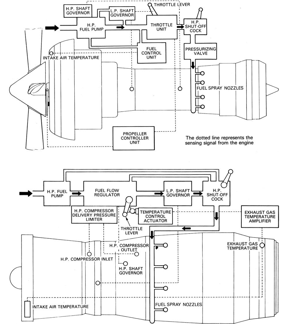
Typical high-pressure (H.P.) fuel control systems for a turbo-propeller engine and a turbo-jet engine are shown in simplified form in Figure 7–3, each basically consisting of an H.P. pump, a throttle control, and a number of fuel spray nozzles. In addition, certain sensing devices are incorporated to provide automatic control of the fuel flow in response to engine requirements. On the turbo-propeller engine, the fuel and propeller systems are coordinated to produce the appropriate fuel/rpm combination.
The usual method of varying the fuel flow to the spray nozzles is by adjusting the output of the H.P. fuel pump. This is effected through a servo system in response to some or all of the following:
2. Air temperature and pressure
3. Rapid acceleration and deceleration
4. Signals of engine speed, engine gas temperature, and compressor delivery pressure
Pressure Control (Turbo-Propeller Engine)
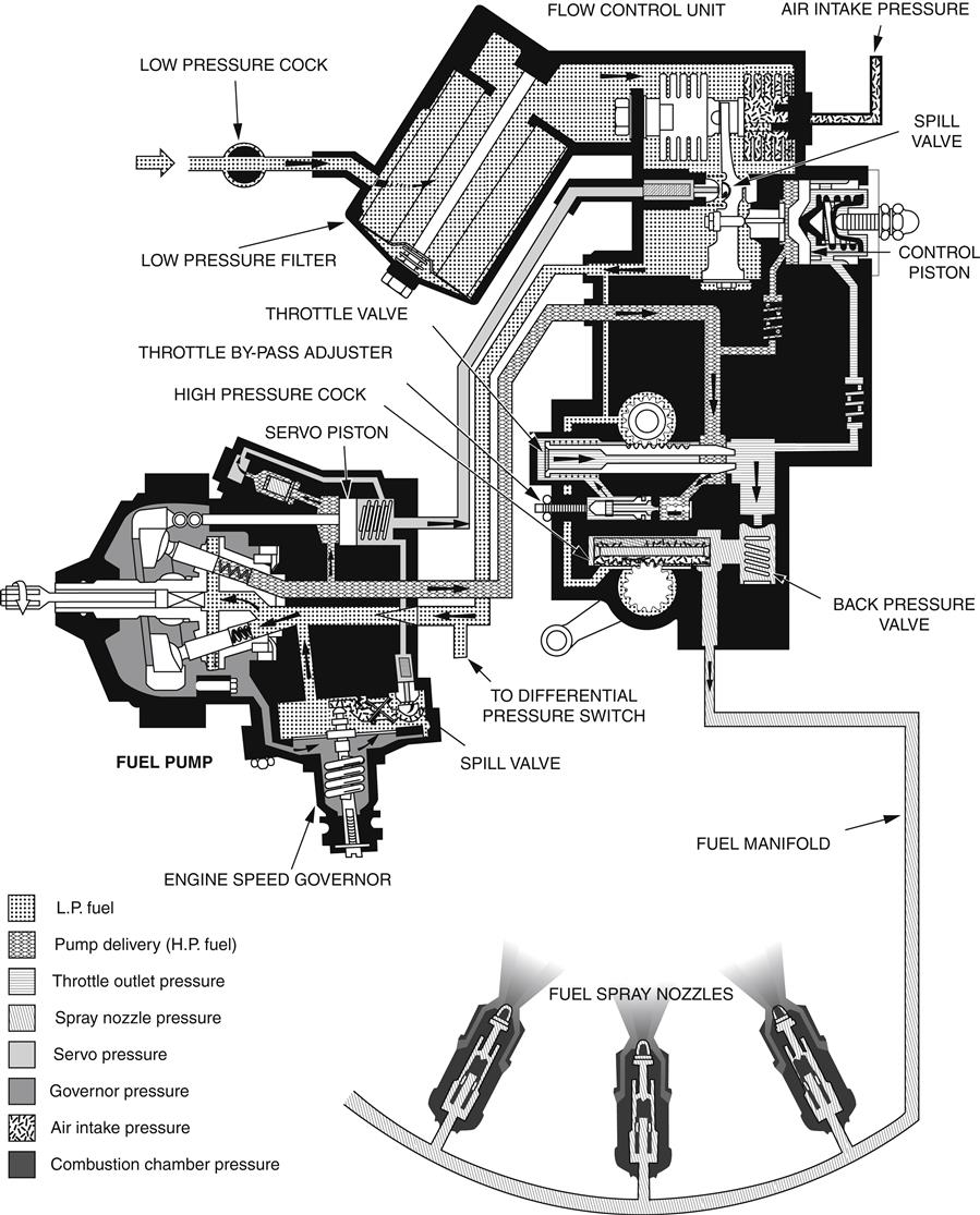
The pressure control system (Figure 7–4) is a typical system as fitted to a turbo-propeller engine where the rate of engine acceleration is restricted by a propeller speed controller. The fuel pump output is automatically controlled by spill valves in the flow control unit (F.C.U.) and the engine speed governor. These valves, by varying the fuel pump servo pressure, adjust the pump stroke to give the correct fuel flow to the engine.
At steady running conditions, at a given air intake pressure and below governed speed, the spill valve in the F.C.U. is in a sensitive position, creating a balance of forces across the fuel pump servo piston and ensuring a steady pressure to the throttle valve.
When the throttle is slowly opened, the pressure to the throttle valve falls and allows the F.C.U. spill valve to close, so increasing the servo pressure and pump delivery. As the pressure to the throttle is restored, the spill valve returns to its sensitive or controlling position, and the fuel pump stabilizes its output to give the engine speed for the selected throttle position. The reverse sequence occurs as the throttle is closed.
A reduction of air intake pressure, due to a reduction of aircraft forward speed or increase in altitude, causes the F.C.U. capsule to expand, thus increasing the bleed from the F.C.U. spill valve. This reduces fuel pump delivery until the fuel flow matches the airflow and the reduced H.P. pump delivery (throttle inlet pressure), allows the spill valve to return to its sensitive position. Conversely, an increase in air intake pressure reduces the bleed from the spill valve and increases the fuel flow. The compensation for changes in air intake pressure is such that fuel flow cannot be increased beyond the predetermined maximum permissible for static International Standard Atmosphere (I.S.A.) sea-level conditions.
The engine speed governor prevents the engine from exceeding its maximum speed limitation. With increasing engine speed, the centrifugal pressure from the fuel pump rotor radial drillings increases and this is sensed by the engine speed governor diaphragm. When the engine reaches its speed limitation, the diaphragm is deflected to open the governor spill valve, thus overriding the F.C.U., and preventing any further increase in fuel flow. Some pressure control systems employ a hydro-mechanical governor.
The governor spill valve also acts as a safety relief valve. If the fuel pump delivery pressure exceeds its maximum controlling value, the servo pressure acting on the orifice area of the spill valve forces the valve open regardless of the engine speed, so preventing any further increase in fuel delivery pressure.
Pressure Control (Turbo-Jet Engine)
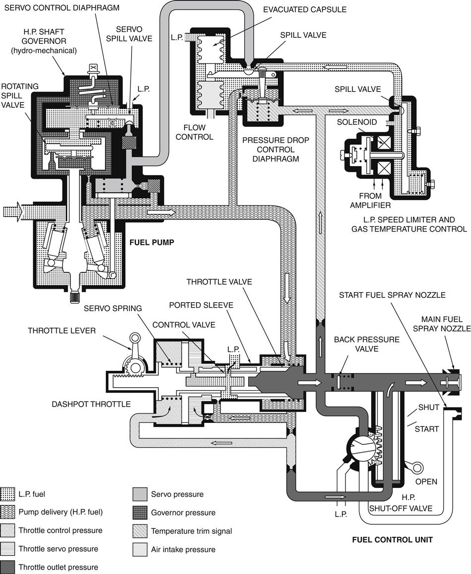
In the pressure control system illustrated in Figure 7–5, the rate of engine acceleration is controlled by a dashpot throttle unit. The unit forms part of the fuel control unit and consists of a servo-operated throttle, which moves in a ported sleeve, and a control valve. The control valve slides freely within the bore of the throttle valve and is linked to the pilot’s throttle by a rack and pinion mechanism. Movement of the throttle lever causes the throttle valve to progressively uncover ports in the sleeve and thus increase the fuel flow. Figure 7–6 shows the throttle valve and control valve in their various controlling positions.
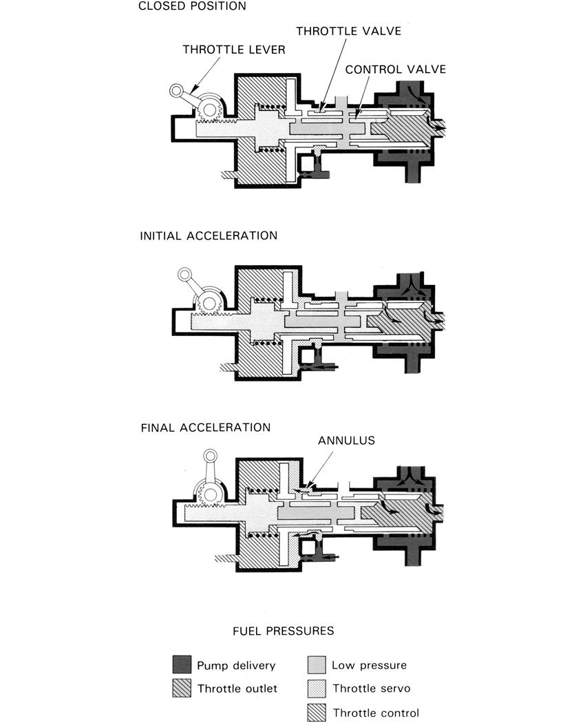
At steady running conditions, the dashpot throttle valve is held in equilibrium by throttle servo pressure opposed by throttle control pressure plus spring force. The pressures across the pressure drop control diaphragm are in balance and the pump servo pressure adjusts the fuel pump to give a constant fuel flow.
When the throttle is opened, the control valve closes the low-pressure (L.P.) fuel port in the sleeve and the throttle servo pressure increases. The throttle valve moves towards the selected throttle position until the L.P. port opens and the pressure balance across the throttle valve is restored. The decreasing fuel pressure difference across the throttle valve is sensed by the pressure drop control diaphragm, which closes the spill valve to increase the pump servo pressure and therefore the pump output. The spill valve moves into the sensitive position, controlling the pump servo mechanism so that the correct fuel flow is maintained for the selected throttle position.
During initial acceleration, fuel control is as described previously; however, at a predetermined throttle position the engine can accept more fuel and at this point the throttle valve uncovers an annulus, so introducing extra fuel at a higher pressure (pump delivery through one restrictor). This extra fuel further increases the throttle servo pressure, which increases the speed of throttle valve travel and the rate of fuel supply to the spray nozzle.
On deceleration, movement of the control valve acts directly on the throttle valve through the servo spring. Control valve movement opens the flow ports through the control valve and throttle valve, to bleed servo fuel through the L.P. port. Throttle control pressure then moves the throttle valve towards the closed position, thus reducing the fuel flow to the spray nozzles.
Changes in air intake pressure, due to a change in aircraft altitude or forward speed, are sensed by the capsule assembly in the fuel control unit. With increased altitude and a corresponding decrease in air intake pressure, the evacuated capsule opens the spill valve, so causing a reduction in pump stroke until the fuel flow matches the airflow. Conversely, an increase in air intake pressure closes the spill valve to increase the fuel flow.
H.P. compressor shaft rpm is governed by a hydro-mechanical governor that uses hydraulic pressure proportional to engine speed as its controlling parameter. A rotating spill valve senses the engine speed and the controlling pressure is used to limit the pump stroke and so prevent overspeeding of the H.P. shaft rotating assembly. The controlling pressure is unaffected by changes in fuel specific gravity.
At low H.P. shaft speeds, the rotating spill valve is held open, but as engine speed increases, centrifugal loading moves the valve towards the closed position against the diaphragm loads. This restricts the bleed of fuel to the L.P. side of the valve until, at governed speed, the governor pressure deflects the servo control diaphragm and opens the servo spill valve to control the fuel flow and thereby the H.P. shaft speed.
If the engine gas temperature attempts to exceed the maximum limitation, the current in the L.P. speed limiter and temperature control solenoid is reduced. This opens the spill valve to reduce the pressure on the pressure drop control diaphragm. The flow control spill valve then opens to reduce the pump servo pressure and fuel pump output.
To prevent the L.P. compressor from overspeeding, multi-spool engines usually have an L.P. compressor shaft speed governor. A signal of L.P. shaft speed and intake temperature is fed to an amplifier and solenoid valve, the valve limiting the fuel flow in the same way as the gas temperature control.
The system described uses main and starting spray nozzles under the control of an H.P. shutoff valve. Two starting nozzles are fitted in the combustion chamber, each being forward of an igniter plug. When the engine has started, the fuel flow to these nozzles is cut off by the H.P. shutoff valve.
To ensure that a satisfactory fuel pressure to the spray nozzles is maintained at high altitudes, a back pressure valve, located downstream of the throttle valve, raises the pressure levels sufficiently to ensure satisfactory operation of the fuel pump servo system.
Flow Control
A flow control fuel system is generally more compact than a pressure control system and is not sensitive to flow effect of variations downstream of the throttle. The fuel pump delivery pressure is related to engine speed; thus, at low engine speeds pump delivery pressure is quite low. The fuel pump output is controlled to give a constant pressure difference across the throttle valve at a constant air intake condition. Various devices are also used to adjust the fuel flow for air intake pressure variations, idling and acceleration control, gas temperature and compressor delivery pressure control.
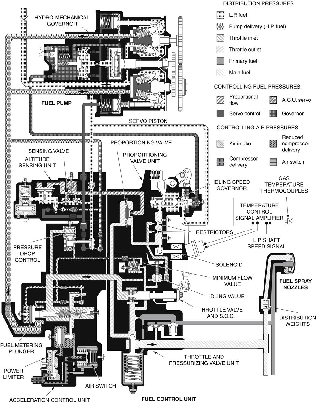
A variation of the flow control system is the proportional flow control system (Figure 7–7), which is more suitable for engines requiring large fuel flows and which also enables the fuel trimming devices to adjust the fuel flow more accurately. A small controlling flow is created that has the same characteristics as the main flow, and this controlling or proportional flow is used to adjust the main flow.
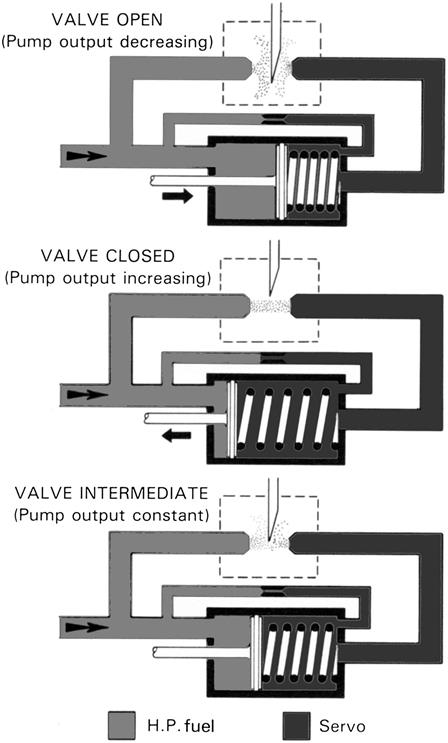
A different type of spill valve, referred to as a kinetic valve, is used in this system. This valve consists of two opposing jets, one subjected to pump delivery pressure and the other to pump servo pressure, and an interrupter blade that can be moved between the jets (Figure 7–8). When the blade is clear of the jets, the kinetic force of the H.P. fuel jet causes the servo pressure to rise (spill valve closed) and the fuel pump moves to maximum stroke to increase the fuel flow. When the blade is lowered between the jets, the pressure jet is deflected and the servo pressure falls, so reducing the pump stroke and the fuel flow. When the engine is steadily running, the blade is in an intermediate position allowing a slow bleed from servo and thus balancing the fuel pump output.
All the controlling devices, except for the engine speed governor, are contained in one combined fuel control unit. The main parts of the control unit are the altitude sensing unit (A.S.U.), the acceleration control unit (A.C.U.), the throttle and pressurizing valve unit, and the proportioning valve unit.
At any steady running condition below governed speed, the fuel pump delivery is controlled to a fixed value by the A.S.U. The spill valve in this unit is held in the controlling position by a balance of forces, spring force and the piston force. The piston is sensitive to the pressure difference across the sensing valve, the pressure difference being created by fuel flowing from the proportioning valve back to the fuel pump inlet.
The proportioning valve diaphragm is held open in a balanced condition allowing fuel to pass to the A.S.U. This means that the restrictor outlet pressure is equal to the throttle outlet pressure and, as their inlet pressures are equal, it follows that the pressure difference across the restrictors and the throttle are equal; therefore, a constant fuel flow is obtained.
When the throttle is slowly opened, the pressure difference across the throttle valve and the proportioning flow restrictors decreases and the proportioning valve diaphragm adjusts its position. This reduces the proportional flow, which closes the A.S.U. spill valve and increases the servo pressure. The fuel pump increases its delivery and this restores the pressure difference across the throttle valve and equalizes the pressure difference across the restrictors. The proportional flow is restored to its original value and the balance of forces in the A.S.U. returns the spill valve to the controlling position.
A variation of air intake pressure, due to a change of aircraft forward speed or altitude, is sensed by the capsule in the A.S.U. A pressure reduction causes the A.S.U. capsule to expand, thus increasing the bleed from the spill valve. This reduces fuel pump delivery until the fuel flow matches the airflow and results in a lower pressure difference across the throttle valve and the proportioning valve restrictors. The reduced proportional flow restores the balance in the A.S.U. that returns the spill valve to its controlling position. Conversely, an increase in aircraft forward speed increases the air intake pressure, which reduces the bleed from the spill valve and increases the fuel flow.
During a rapid acceleration, the sudden decrease in throttle pressure difference is sensed by the A.S.U., causing the spill valve to close. Such a rapid increase in fuel supply would, however, create an excessive gas temperature and also cause the compressor to surge. This occurs because the inertia of the rotating assembly results in an appreciable time lag in the rate of airflow increase. It is essential, therefore, to have an acceleration control to override the A.S.U. to give a corresponding lag in the rate of fuel flow increase.
The rapid initial increase of fuel flow causes a rise in the pressure difference across the fuel metering plunger and this is sensed by a diaphragm in the pressure drop control section. At a fixed value of overfueling, the pressure drop control diaphragm opens its servo spill valve to override the A.S.U. and maintains a constant pressure difference across the metering plunger.
The increased fuel supply causes the engine to accelerate and the fuel metering plunger gives the maximum permissible fuel flow to match the increasing compressor delivery pressure. This it achieves through the A.C.U. servo system, which is under the control of a spill valve operated by compressor delivery air pressure acting on a capsule.
As the compressor delivery pressure continues to rise, the capsule is compressed to open the spill valve and to bleed pressure from above the metering plunger. Pump delivery pressure acting underneath the plunger causes it to lift, this increases the area of the main fuel flow passage.
The pressure drop control spill valve closes to increase the fuel pump delivery and maintains the controlling pressure difference across the plunger. The fuel flow, therefore, progressively rises as airflow through the compressor increases. The degree of overfueling can be automatically changed by the air switch, which increases the pressure signal on to the capsule. The full value of compressor delivery pressure is now passed on to the A.C.U. capsule assembly, thus increasing the opening rate of the metering plunger.
As the controlled overfueling continues, the pressure difference across the throttle valve increases. When it reaches the controlling value, the A.S.U. takes over due to the increasing proportional flow and again gives a steady fuel flow to the spray nozzles.
The engine speed governor can be of the pressure control type described previously, or a hydro-mechanical governor also described previously.
The control of servo pressure by the hydro-mechanical governor is very similar to that of the pressure control governor, except that the governor pressure is obtained from pump delivery fuel passing through a restrictor and the restricted pressure is controlled by a rotating spill valve; this type of governor is unaffected by changes in fuel specific gravity.
At low engine speeds, the rotating spill valve is held open; however, as engine speed increases, centrifugal loading moves the valve towards the closed position against the diaphragm loads. This restricts the bleed of H.P. fuel to the L.P. side of the drum until, at governed speed, the governor pressure deflects the diaphragm and opens the fuel pump servo pressure spill valve to control the maximum fuel flow and engine speed.
If the engine gas temperature exceeds its maximum limitation, the solenoid on the proportioning valve unit is progressively energized. This causes a movement of the rocker arm to increase the effective flow area of one restrictor, thus increasing the proportional flow and opening the A.S.U. spill valve to reduce servo pressure. The fuel flow is thus reduced and any further increase of gas temperature is prevented.
To prevent the L.P. compressor from overspeeding, some twin-spool engines have an L.P. shaft rpm governor. A signal of L.P. shaft speed is fed to an amplifier and solenoid valve, which limits the fuel output in the same way as the gas temperature control.
An idling speed governor is often fitted to ensure that the idling rpm does not vary with changing engine loads. A variation of idling rpm causes the rocker arm to move and alter the proportional flow, and the A.S.U. adjusts the pump delivery until the correct idling rpm is restored.
On some engines, a power limiter is used to prevent overstressing of the engine. To achieve this, compressor delivery pressure acts on the power limiter capsule. Excess pressure opens the power limiter atmospheric bleed to limit the pressure on the A.C.U. capsule and this controls the fuel flow through the metering plunger.
To enable the engine to be relit and to prevent flame-out at altitude, the engine idling rpm is made to increase with altitude. To achieve this, some engines incorporate a minimum flow valve that adds a constant minimum fuel flow to that passing through the throttle valve.
Combined Acceleration and Speed Control
The combined acceleration and speed control system (Figure 7–9) is a mechanical system without small restrictors or spill valves. It is also an all-speed governor system and therefore needs no separate governor unit for controlling the maximum rpm. The controlling mechanism is contained in one unit, usually referred to as the fuel flow regulator (F.F.R.). An H.P. fuel pump is used and the fuel pump servo piston is operated by H.P. fuel on one side and main spray nozzle (servo) pressure on the spring side.
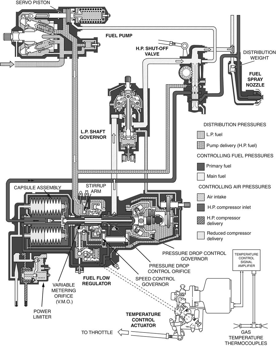
The F.F.R. is driven by the engine through a gear train and has two centrifugal governors, known as the speed control governor and the pressure drop control governor. Two sliding valves are also rotated by the gear train. One valve, known as the variable metering sleeve, has a triangular orifice, known as the variable metering orifice (V.M.O.), and this sleeve is given axial movement by a capsule assembly. The V.M.O. sleeve moves inside a non-rotating governor sleeve that is moved axially by the speed control governor. The other valve, known as the pressure drop control valve, is provided with axial movement by the pressure drop control governor and has a triangular orifice, known as the pressure drop control orifice, and a fixed-area rectangular orifice. The speed control governor is set by the throttle lever through a cam, a spring, and a stirrup arm inside the regulator.
At any steady running condition, the engine speed is governed by the regulator controlling the fuel flow. The fuel pump delivery is fixed at a constant value by applying the system pressure difference to the fuel pump servo piston. This is arranged to balance the servo piston spring forces.
When the air intake pressure is at a constant value, the rotating V.M.O. sleeve is held in a fixed axial position by the capsule loading. The fixed throttle setting maintains a set load on the speed control governor and, as the rpm is constant, the governor sleeve is held in a fixed position.
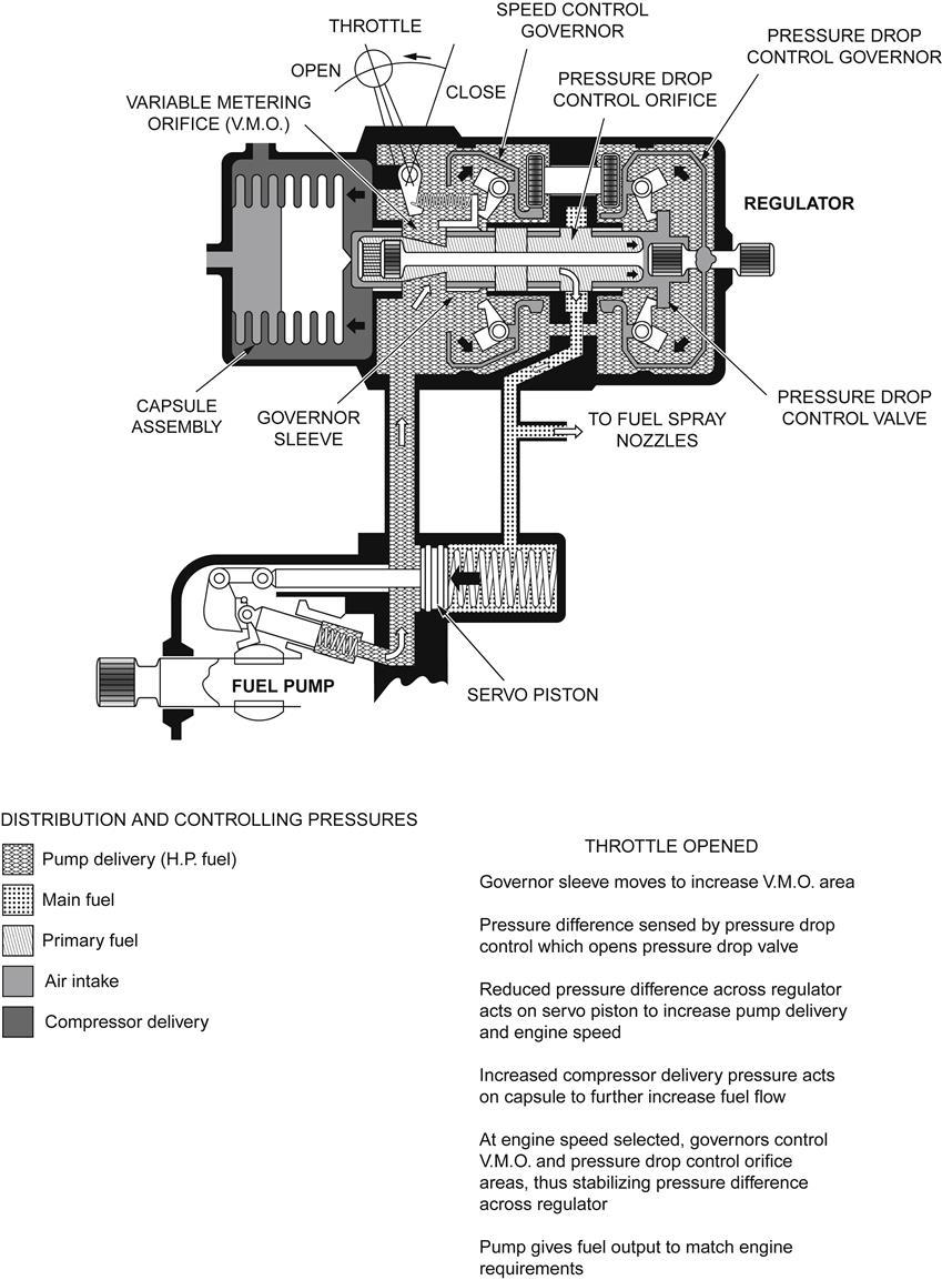
The fuel pump delivery is passed to the annulus surrounding the V.M.O.; the annulus area is controlled by the governor sleeve, and the exposed area of the orifice is set by the axial position of the V.M.O. sleeve. Consequently, fuel passes to the inside of the sleeve at a constant flow and therefore at a constant pressure difference.
The pressure drop control valve, which also forms a piston, senses the pressure difference across the V.M.O. and maintains the fuel flow at a fixed value in relation to a function of engine speed, by controlling the exposed area of the pressure drop control orifice.
When the throttle is slowly opened, the load on the speed control governor is increased, so moving the governor sleeve to increase the V.M.O. annulus area. The effect of opening the V.M.O. is to reduce the pressure difference and this is sensed by the pressure drop control governor, which opens the pressure drop valve. The reduced system pressure difference is immediately sensed by the fuel pump servo piston, which increases the pump stroke and consequently the fuel output. The increased compressor delivery pressure acts on the capsule assembly that gradually opens the V.M.O. so that the fuel flow and engine speed continue to increase. At the speed selected, centrifugal forces acting on the speed control governor move the governor sleeve to reduce the V.M.O. annulus area. The resultant increased pressure difference is sensed by the pressure drop control governor, which adjusts the pressure drop valve to a point at which the pump servo system gives an output to match the engine requirements. The function of the governors and the control of the fuel flow is shown diagrammatically in Figure 7–10.
During a rapid acceleration, the initial degree of overfueling is mechanically controlled by a stop that limits the opening movement of the speed control governor sleeve. A similar stop also prevents the fuel supply from being completely cut off by the governor sleeve during a rapid deceleration.
Changes in altitude or forward speed of the aircraft vary the fuel flow required to maintain a constant engine speed. To provide this control, the capsule assembly senses changes in H.P. compressor inlet and delivery pressures and adjusts the V.M.O. accordingly. For instance, as the aircraft altitude increases, the compressor delivery pressure falls and the capsule assembly expands to reduce the V.M.O. The increased system pressure drop is sensed by the fuel pump servo piston, which adjusts the pump output to match the reduced airflow and so maintain a constant engine speed. Conversely, an increase in aircraft forward speed causes the capsule assembly to be compressed and increase the V.M.O. The reduced system pressure drop causes the fuel pump to increase its output to match the increased airflow.
To prevent the maximum gas temperature from being exceeded, fuel flow is reduced in response to signals from thermocouples sensing the temperature. When the maximum temperature is reached, the signals are amplified and passed to a rotary actuator, which adjusts the throttle mechanism. This movement has the same effect on fuel flow as manual operation of the throttle.
To ensure that the engine is not overstressed, the H.P. compressor delivery pressure is controlled to a predetermined value. At this value, a pressure-limiting device, known as a power limiter, reduces the pressure in the capsule chamber, thus allowing the capsule assembly to expand and reduce the V.M.O. so preventing any further increase in fuel flow.
A governor prevents the L.P. compressor shaft from exceeding its operating limitations and also acts as a maximum speed governor in an event of a failure of the F.F.R. The governor provides a variable restrictor between the regulator and the main fuel spray nozzle manifold. Should the L.P. compressor reach its speed limitation, flyweights in the governor move a sleeve valve to reduce the flow area. The increased system pressure drop is sensed by the fuel pump servo piston, which reduces the fuel flow to the spray nozzles.
This fuel system has no pressurizing valve to divide the flow from the fuel pump into main and primary fuel flows. Primary fuel pressure is taken from the fixed-area orifice of the pressure drop control valve. This pressure is always higher than the main fuel pressure and it is not shut off by the pressure drop control piston. It therefore gives a satisfactory idling fuel flow at all altitudes.
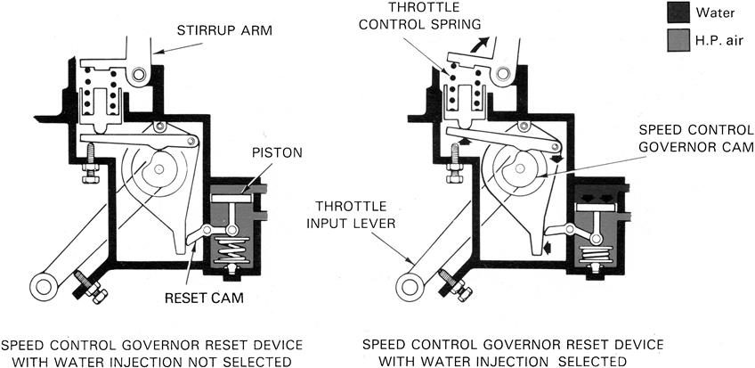
On engines featuring water injection, a reset device (Figure 7–11), operated by a piston and reset cam, increases the loading on the throttle control spring and stirrup arm, thus selecting a higher engine speed during water injection. To prevent the power limiter (Figure 7–9) from canceling the effect of water injection, a capsule in the limiter is subjected to water pressure to raise the compressor delivery pressure at which the power limiter operates.
Pressure Ratio Control
The pressure ratio control (Figure 7–12) is a mechanical system similar to the combined acceleration and speed control system, but uses the ratio of H.R. compressor delivery pressure to air intake pressure (1¾/P1) as the main controlling parameter. It needs no separate governor unit for controlling the maximum rpm The controlling mechanism is contained in one unit, which is usually referred to as a fuel flow regulator (F.F.R.). A gear-type pump is used, as described later, and the pump output to the F.F.R. is controlled by a pressure drop spill valve.
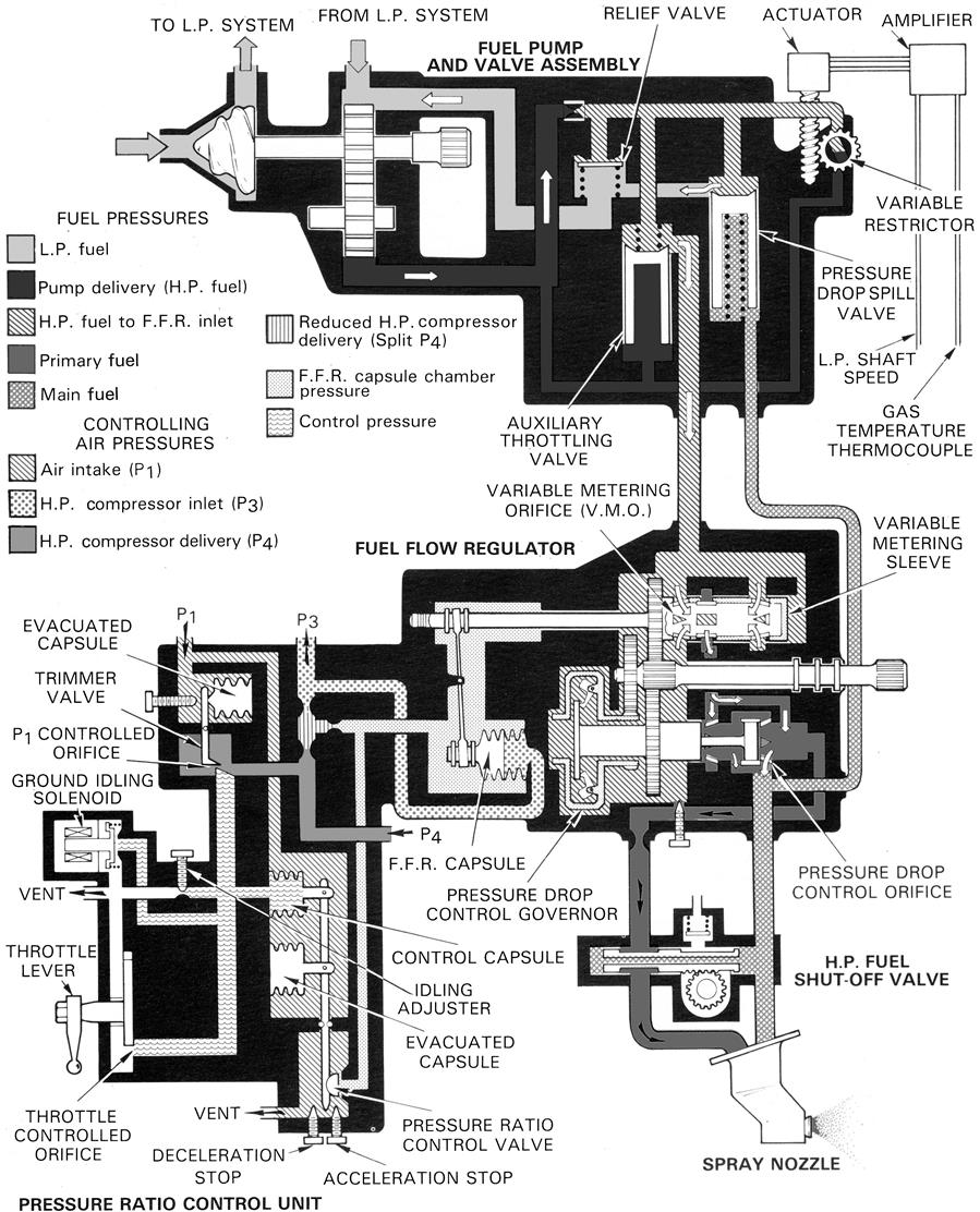
The F.F.R. is driven by the engine through a gear train and has two rotating valves. One valve, known as a variable metering sleeve, has a triangular orifice, known as the variable metering orifice (V.M.O.), and this sleeve is given axial movement by a capsule assembly. The other valve, known as the pressure drop control valve, is provided with axial movement by a centrifugal governor, known as a pressure drop control governor. Both valves form variable restrictors which control the fuel flow to the spray nozzles.
Control of the V.M.O. area is a function of a pressure ratio control unit housed in the F.F.R. A pressure ratio control valve, subjected to P4 and P1 pressures, regulates the movement of the F.F.R. capsule and thus controls the V.M.O. area to produce the pressure ratio dictated by the throttle or power lever.
At any steady running condition, the output of the fuel pump is greater than the engine requirement. The pressure drop spill valve is open to allow surplus fuel to return to the inlet side of the pump. This action controls the fuel delivery to that demanded by the F.F.R.
When the throttle is slowly opened, the throttle-controlled orifice is increased and the control pressure falls, thus allowing the pressure ratio control valve to move towards the closed position (acceleration stop). F.F.R. capsule chamber pressure increases and the capsule moves the metering sleeve to increase the V.M.O. area. The effect of opening the V.M.O. is to reduce the pressure difference and this is sensed by the pressure drop governor, which opens the pressure drop control orifice. The reduced system pressure difference is immediately sensed by the pressure drop spill valve, which moves towards the closed position and consequently increases the fuel output. The increased fuel flow accelerates the engine with a subsequent increase in pressure ratio (P4/P1). When the required pressure ratio is reached, the pressure ratio control valve opens and the F.F.R. capsule chamber pressure reduces. The capsule assembly expands, moving the V.M.O. sleeve to reduce the orifice area. The resultant increased pressure difference is sensed by the pressure drop control governor, which adjusts the pressure drop control orifice to a point at which the pressure drop spill valve gives a fuel output consistent with steady running requirements.
During a rapid acceleration, the degree of overfueling is mechanically controlled by the acceleration stop, which limits the movement of the pressure ratio control valve. A similar stop prevents the fuel supply from being completely cut off during a rapid deceleration.
When accelerating to a higher P4/P1 ratio, the throttle control orifice is increased. The reduced pressure allows the pressure ratio control capsule to contract so that the valve contacts the acceleration stop. F.F.R. capsule chamber pressure increases and the capsule moves to increase the V.M.O. area. This action continues until the required P4/P1 ratio is reached. The increased P4 pressure allows the pressure ratio control capsule to re-expand and the valve to return to the steady running position.
A change in altitude of the aircraft requires a variation in fuel flow to match the engine thrust and aircraft climb requirement. The normal effect of an altitude increase is to decrease the P1 and P4 pressures, thus opening the pressure ratio control valve and allowing the F.F.R. capsule to expand to reduce the V.M.O. area and, in consequence, the fuel flow. However, to match the engine thrust and aircraft climb requirement it is necessary to increase the P4/P1 ratio with increasing altitude. This is done by a trimmer valve and a capsule that is subjected to P1 pressure. As P1 pressure decreases, the trimmer valve moves across the P1 controlled orifice to reduce the control pressure. This is sensed by the control capsule, which, by acting on the pressure ratio control valve, slows the closure of the V.M.O. as altitude is increased. This maintains the thrust requirement with the throttle at a fixed position.
To prevent the maximum L.P. compressor rpm and engine gas temperature from being exceeded, a valve known as the auxiliary throttling valve is fitted in the outlet from the fuel pump. Under steady running conditions, the valve is held open by spring force. When limiting conditions are reached, the fuel flow is reduced in response to speed and temperature signals from the engine. The signals are amplified and passed to a rotary actuator that reduces the area of a variable restrictor. The effect of this is to increase the fuel pressure, which partially closes the throttling valve. H.P. fuel pressure acting on the face of the pressure drop spill valve is increased and the spill valve opens to reduce the fuel flow to the spray nozzles.
H.P. shaft speed is also governed by the auxiliary throttling valve. Should other controlling devices fail and pump speed increase, the fuel pressure closes the throttling valve and opens the pressure drop spill valve to reduce the fuel flow.
With the throttle closed, idling condition is determined by controlling the amount of air being vented through the idling adjuster and the ground idling solenoid valve. With both bleeds in operation, satisfactory flight idling for the air off-takes is ensured. By closing the solenoid valve a lower power condition for ground idling is obtained.
This fuel system, like the combined acceleration and speed control system, has no pressurizing valve to divide the flow from the fuel pump into main and primary flows.
Electronic Engine Control
As stated previously, some engines utilize a system of electronic control to monitor engine performance and make necessary control inputs to maintain certain engine parameters within predetermined limits. The main areas of control are engine shaft speeds and exhaust gas temperature (E.G.T.) which are continuously monitored during engine operation. Some types of electronic control function as a limiter only, that is, should engine shaft speed or E.G.T. approach the limits of safe operation, then an input is made to the fuel flow regulator (F.F.R.) to reduce the fuel flow thus maintaining shaft speed or E.G.T. at a safe level. Supervisory control systems may contain a limiter function but, basically, by using aircraft generated data, the system enables a more appropriate thrust setting to be selected quickly and accurately by the pilot. The control system then makes small control adjustments to maintain engine thrust consistent with that pre-set by the pilot, regardless of changing atmospheric conditions. Full authority digital engine control (F.A.D.E.C.) takes over virtually all of the steady state and transient control intelligence and replaces most of the hydro-mechanical and pneumatic elements of the fuel system. The fuel system is thus reduced to a pump and control valve, an independent shutoff cock and a minimum of additional features necessary to keep the engine safe in the event of extensive electronic failure.
Full authority fuel control (F.A.F.C.) provides full electronic control of the engine fuel system in the same way as F.A.D.E.C. but has none of the transient control intelligence capability used to control the compressor airflow system as the existing engine control system is used for these.
Speed and Temperature Control Amplifiers
The speed and temperature control amplifier receives signals from thermocouples measuring E.G.T. and from speed probes sensing L.P. and in some cases I.P. shaft speeds (N1 and N2). The amplifier basically comprises speed and temperature channels that monitor the signals sensed. If either N1, N2, or E.G.T. exceeds pre-set datums, the amplifier output stage is triggered to connect an electrical supply to a solenoid valve or a variable restrictor that overrides the F.F.R. and causes a reduction in fuel flow. The limiter will only relinquish control back to the F.F.R. if the input conditions are altered (altitude, speed, ambient temperature, or throttle lever position). The limiter system is designed to protect against parameters exceeding their design values under normal operation and basic fuel system failures.
Engine Supervisory Control
The engine supervisory control (E.S.C.) system performs a supervisory function by trimming the fuel flow scheduled by the fuel flow governor (F.F.G.) to match the actual engine power with a calculated engine power for a given throttle angle. The E.S.C. provides supervisory and limiting functions by means of a single control output signal to a torque motor in the F.F.G. In order to perform its supervisory function the E.S.C. monitors inputs of throttle angle, engine bleed state, engine pressure ratio (E.P.R.), and air data computer information (altitude, Mach number, and temperatures). From this data the supervisory channel predicts the value of N1 required to achieve the command E.P.R. calculated for the throttle angle set by the pilot. Simultaneously a comparison is made between the command E.P.R. and the actual E.P.R. and the difference is compared with a programmed datum.
During acceleration the comparitor connects the predicted value of N1 to the limiter channel until the difference between the command and actual E.P.R. is approximately 0.03 E.P.R. At this point the predicted L.P. shaft speed is disconnected and the E.P.R. difference signal is connected to the limiter channel.
The final output from the supervisory channel, in the form of an error signal, is supplied to a “lowest wins” circuit along with the error signals from the limiter channel. While the three error signals remain positive (N1 and E.G.T. below datum level and actual E.P.R. below command E.P.R.) no output is signaled to the torque motor. If, however, the output stage of the E.S.C. predicts that E.G.T. will exceed datum or that N1 will either exceed its datum or the predicted level for the command E.P.R., then a signal is passed to the torque motor to trim the fuel flow.
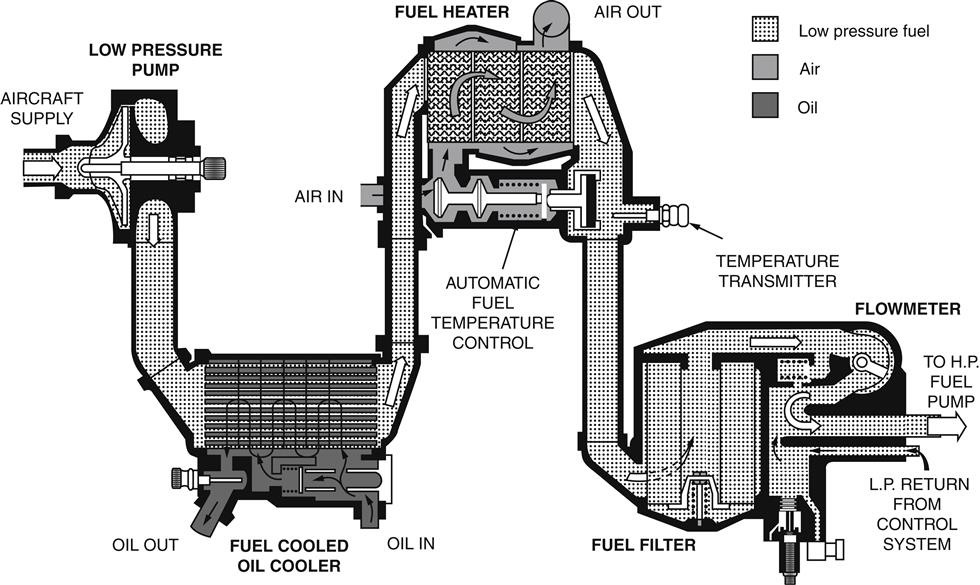
Low-Pressure Fuel System
An L.P. system (Figure 7–13) must be provided to supply the fuel to the engine at a suitable pressure, rate of flow and temperature to ensure satisfactory engine operation. This system may include an L.P. pump to prevent vapor locking and cavitation of the fuel, and a fuel heater to prevent ice crystals forming. A fuel filter is always used in the system and in some instances the flow passes through an oil cooler. Transmitters may also be used to signal fuel pressure, flow, and temperature.
Fuel Pumps
There are two basic types of fuel pump, the plunger-type pump and the constant-delivery gear-type pump; both of these are positive displacement pumps. Where low pressures are required at the fuel spray nozzles, the gear-type pump is preferred because of its lightness.
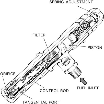
Plunger-Type Fuel Pump
The pump shown in Figure 7–14 is of the single-unit, variable-stroke, plunger type; similar pumps may be used as double units depending upon the engine fuel flow requirements.
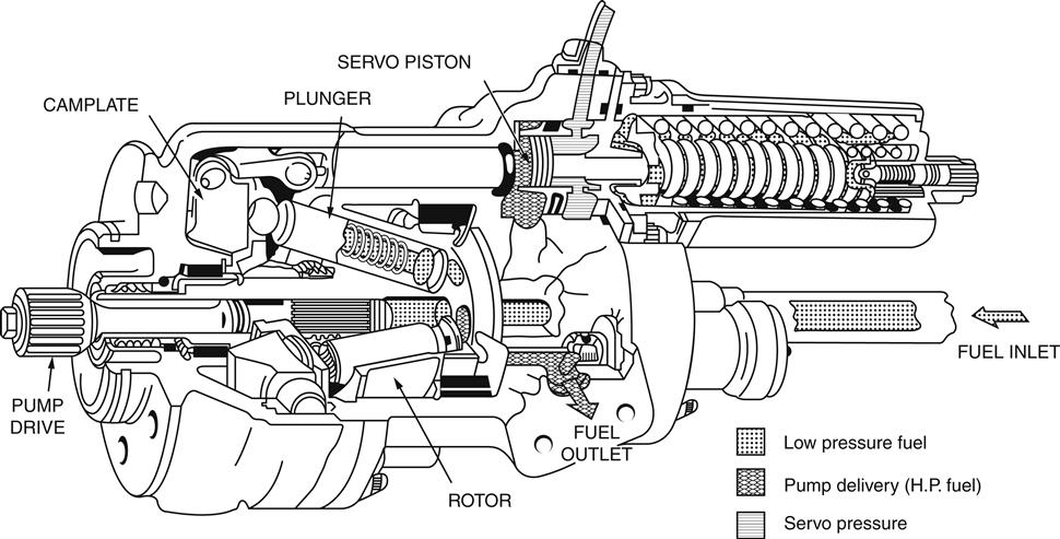
The fuel pump is driven by the engine gear train and its output depends upon its rotational speed and the stroke of the plungers. A single-unit fuel pump can deliver fuel at the rate of 100–2000 gallons per hour at a maximum pressure of about 2000 lb. per square inch. To drive this pump, as much as 60 horsepower may be required.
The fuel pump consists of a rotor assembly fitted with several plungers, the ends of which project from their bores and bear on to a non-rotating camplate. Due to the inclination of the camplate, movement of the rotor imparts a reciprocating motion to the plungers, thus producing a pumping action. The stroke of the plungers is determined by the angle of inclination of the camplate. The degree of inclination is varied by the movement of a servo piston that is mechanically linked to the camplate and is biased by springs to give the full stroke position of the plungers. The piston is subjected to servo pressure on the spring side and on the other side to pump delivery pressure; thus variations in the pressure difference across the servo piston cause it to move with corresponding variations of the camplate angle and, therefore, pump stroke.
Gear-Type Fuel Pump
The gear-type fuel pump (Figure 7–12) is driven from the engine and its output is directly proportional to its speed. The fuel flow to the spray nozzles is controlled by recirculating excess fuel delivery back to inlet. A spill valve, sensitive to the pressure drop across the controlling units in the system, opens and closes as necessary to increase or decrease the spill.
Fuel Spray Nozzles
The final components of the fuel system are the fuel spray nozzles, which have as their essential function the task of atomizing or vaporizing the fuel to ensure its rapid burning. The difficulties involved in this process can be readily appreciated when one considers the velocity of the air stream from the compressor and the short length of combustion system in which the burning must be completed.
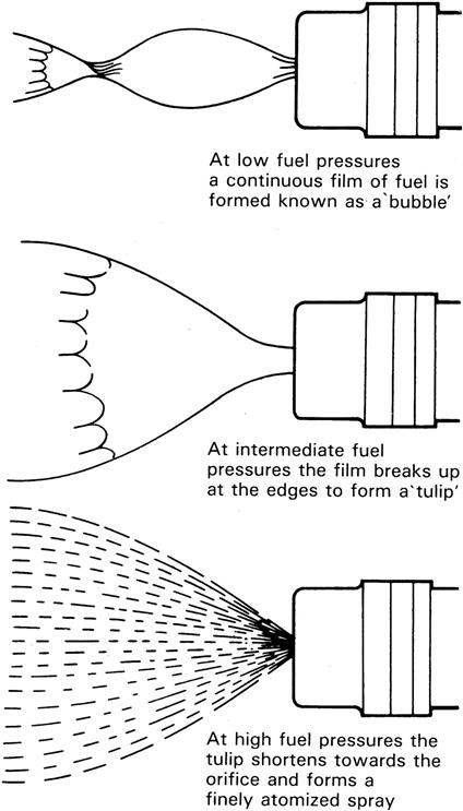
An early method of atomizing the fuel is to pass it through a swirl chamber where tangentially disposed holes or slots imparted swirl to the fuel by converting its pressure energy to kinetic energy. In this state, the fuel is passed through the discharge orifice that removes the swirl motion as the fuel is atomized to form a cone-shaped spray. This is called “pressure jet atomization.” The rate of swirl and pressure of the fuel at the fuel spray nozzle are important factors in good atomization. The shape of the spray is an indication of the degree of atomization as shown in Figure 7–15. Later fuel spray nozzles utilize the airspray principle that employs high velocity air instead of high velocity fuel to cause atomization. This method allows atomization at low fuel flow rates (provided sufficient air velocity exists) thus providing an advantage over the pressure jet atomizer by allowing fuel pumps of a lighter construction to be used.
The atomizing spray nozzle, as distinct from the vaporizing burner, has been developed in five fairly distinct types, the Simplex, the variable port (Lubbock), the Duplex or Duple, the spill type, and the airspray nozzle.
The Simplex spray nozzle shown in Figure 7–16 was first used on early jet engines. It consists of a chamber, which induces a swirl into the fuel, and a fixed-area atomizing orifice. This fuel spray nozzle gave good atomization at the higher fuel flows, that is, at the higher fuel pressures, but was very unsatisfactory at the low pressures required at low engine speeds and especially at high altitudes. The reason for this is that the Simplex was, by the nature of its design, a “square law” spray nozzle; that is, the flow through the nozzle is proportional to the square root of the pressure drop across it. This meant that if the minimum pressure for effective atomization was 30 lb. per square inch, the pressure needed to give maximum flow would be about 3000 lb. per square inch. The fuel pumps available at that time were unable to cope with such high pressures so the variable port spray nozzle was developed in an effort to overcome the square law effect.
Although now only of historical value, the variable port or Lubbock fuel spray nozzle (Figure 7–17) made use of a spring-loaded piston to control the area of the inlet ports to the swirl chamber. At low fuel flows, the ports were partly uncovered by the movement of the piston; at high flows, they were fully open. By this method, the square law pressure relationship was mainly overcome and good atomization was maintained over a wide range of fuel flows. The matching of sets of spray nozzles and the sticking of the sliding piston due to dirt particles were, however, difficulties inherent in the design, and this type was eventually superseded by the Duplex and the Duple fuel spray nozzles.
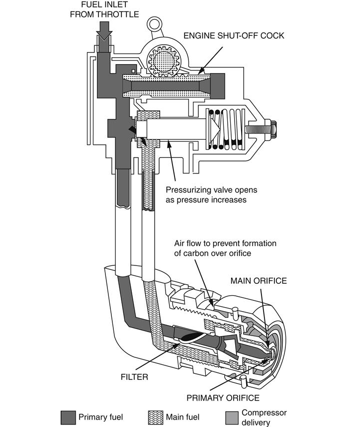
The Duplex and the Duple spray nozzles require a primary and a main fuel manifold and have two independent orifices, one much smaller than the other. The smaller orifice handles the lower flows and the larger orifice deals with the higher flows as the fuel pressure increases. A pressurizing valve may be employed with this type of spray nozzle to apportion the fuel to the manifolds (Figure 7–18). As the fuel flow and pressure increase, the pressurizing valve moves to progressively admit fuel to the main manifold and the main orifices. This gives a combined flow down both manifolds. In this way, the Duplex and Duple nozzles are able to give effective atomization over a wider flow range than the Simplex spray nozzle for the same maximum fuel pressure. Also, efficient atomization is obtained at the low flows that may be required at high altitude. In the combined acceleration and speed control system, the fuel flow to the spray nozzles is apportioned in the F.F.R.
The spill-type fuel spray nozzle can be described as being a Simplex spray nozzle with a passage from the swirl chamber for spilling fuel away. With this arrangement it is possible to supply fuel to the swirl chamber at a high pressure all the time. As the fuel demand decreases with altitude or reduction in engine speed, more fuel is spilled away from the swirl chamber, leaving less to pass through the atomizing orifice. The spill spray nozzles’ constant use of a relatively high pressure means that even at the extremely low fuel flows that occur at high altitude there is adequate swirl to provide constant and efficient atomization of the fuel.
The spill spray nozzle system, however, involves a somewhat modified type of fuel supply and control system from that used with the previous types. A means has to be provided for removing the spill and also for controlling the amount of spill flow at various engine operating conditions. A disadvantage of this system is that excess heat may be generated when a large volume of fuel is being recirculated to inlet. Such heat may eventually lead to a deterioration of the fuel.
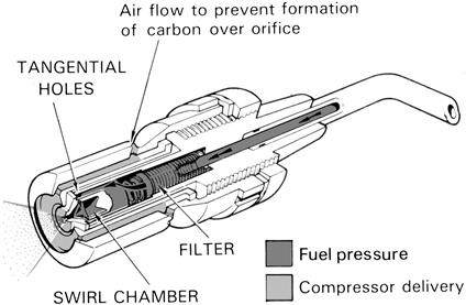
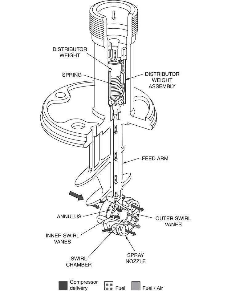
The airspray nozzle (Figure 7–19) carries a proportion of the primary combustion air with the injected fuel. By aerating the spray, the local fuel-rich concentrations produced by other types of spray nozzle are avoided, thus giving a reduction in both carbon formation and exhaust smoke. An additional advantage of the airspray nozzle is that the low pressures required for atomization of the fuel permit the use of the comparatively lighter gear-type pump.
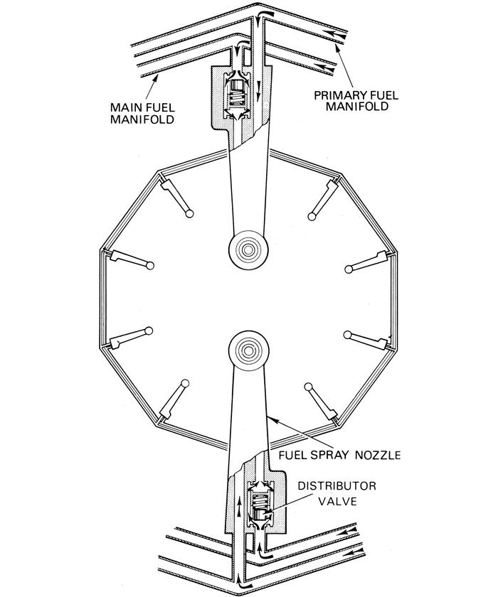
A flow distributor (Figure 7–20) is often required to compensate for the gravity head across the manifold at low fuel pressures to ensure that all spray nozzles pass equal quantities of fuel.
Some combustion systems vaporize the fuel as it enters the combustion zone.
Fuel Heating
On many engines, a fuel-cooled oil cooler is located between the L.P. fuel pump and the inlet to the fuel filter (Figure 7–13), and advantage is taken of this to transfer the heat from the oil to the fuel and thus prevent blockage of the filter element by ice particles. When heat transference by this means is insufficient, the fuel is passed through a second heat exchanger where it absorbs heat from a thermostatically controlled airflow taken from the compressor.
Effect of a Change of Fuel
The main effect on the engine of a change from one grade of fuel to another arises from the variation of specific gravity and the number of heat units obtainable from a gallon of fuel. As the number of heat units per pound is practically the same for all fuels approved for gas turbine engines, a comparison of heat values per gallon can be obtained by comparing specific gravities.
Changes in specific gravity have a definite effect on the centrifugal pressure type of engine speed governor, for with an increase in specific gravity the centrifugal pressure acting on the governor diaphragm is greater. Thus the speed at which the governor controls is reduced, and in consequence the governor must be reset.
With a decrease in specific gravity, the centrifugal pressure on the diaphragm is less and the speed at which the governor controls is increased; in consequence, the pilot must control the maximum rpm by manual operation of the throttle to prevent overspeeding the engine until the governor can be reset. The hydro-mechanical governor is less sensitive to changes of specific gravity than the centrifugal governor and is therefore preferred on many fuel systems.
The pressure drop governor in the combined acceleration and speed control system is density compensated, by using a buoyant material for the governor weights, resulting in fuel being metered on mass flow rather than volume flow.
Changes to a lower grade of fuel can lead to production of carbon, giving a greater flame luminosity and temperature, leading to higher combustor metal temperatures and reduced combustor and turbine life.
Gas Turbine Fuels
Fuels for aircraft gas turbine engines must conform to strict requirements to give optimum engine performance, economy, safety, and overhaul life. Fuels are classed under two headings, kerosene-type fuel and wide-cut gasoline-type fuel.
Fuel Requirements
In general, a gas turbine fuel should have the following qualities:
1. Be “pumpable” and flow easily under all operating conditions
2. Permit engine starting at all ground conditions and give satisfactory flight relighting characteristics
3. Give efficient combustion at all conditions
4. Have as high a calorific value as possible
5. Produce minimal harmful effects on the combustion system or the turbine blades
6. Produce minimal corrosive effects on the fuel system components
7. Provide adequate lubrication for the moving parts of the fuel system
The pumping qualities of the fuel depend upon its viscosity or thickness, which is related to fuel temperature. Fuel must be satisfactory down to approximately –50°C. As the fuel temperature falls, ice crystals may form to cause blockage of the fuel filter or the orifices in the fuel system. Fuel heating and anti-icing additives are available to alleviate this problem.
For easy starting, the gas turbine engine depends upon the satisfactory ignition of the atomized spray of fuel from the fuel spray nozzles, assuming that the engine is being motored at the required speed. Satisfactory ignition depends upon the quality of fuel in two ways:
1. The volatility of the fuel; that is, its ability to vaporize easily, especially at low temperatures.
2. The degree of atomization, which depends upon the viscosity of the fuel, the fuel pressure applied, and the design of the atomizer.
The calorific value (Figure 7–21) of a fuel is an expression of the heat or energy content per pound or gallon that is released during combustion. This value, which is usually expressed in British thermal units, influences the range of an aircraft. Where the limiting factor is the capacity of the aircraft tanks, the calorific value per unit volume should be as high as possible, thus enabling more energy, and hence more aircraft range, to be obtained from a given volume of fuel. When the useful payload is the limiting factor, the calorific value per unit of weight should be as high as possible, because more energy can then be obtained from a minimum weight of fuel. Other factors that affect the choice of heat per unit of volume or weight must also be taken into consideration; these include the type of aircraft, the duration of flight, and the required balance between fuel weight and payload.

Turbine fuels tend to corrode the components of the fuel and combustion systems mainly as a result of the sulfur and water content of the fuel. Sulfur, when burned in air, forms sulfur dioxide; when mixed with water this forms sulfurous acid and is very corrosive, particularly on copper and lead. Because it is impracticable to completely remove the sulfur content, it is essential that the sulfur be kept to a controlled minimum. Although free water is removed prior to use, dissolved water, i.e., water in solution, cannot be effectively removed, as a fuel would reabsorb moisture from the atmosphere when stored in a vented aircraft or storage tank.
All gas turbine fuels are potentially dangerous; handling storage precautions should be strictly observed.
Vapor Locking and Boiling
The main physical difference between kerosene and wide-cut fuels is their degree of volatility, the latter type of fuel having a higher volatility, thus increasing the problem of vapor locking boiling. With kerosene-type fuels, the volatility is controlled by distillation and flash point, but with the wide-cut fuels it is controlled by distillation Reid Vapor Pressure (R.V.P.) test. In this test, the absolute pressure of the fuel is recorded by special apparatus with the fuel temperature at 37.8°C (100°F).
Kerosene has a low vapor pressure and will boil only at extremely high altitudes or high temperatures, whereas a wide-cut fuel will boil at a much lower altitude.
The fuel temperature during flight depends upon altitude, rate of climb, duration at altitude, and kinetic heating due to forward speed. When boiling does occur, the vapor loss can be very high, especially with wide-cut fuels, and this may cause vapor locking with consequent malfunctions of the engine fuel system and fuel metering equipment.
To obviate or reduce the risk of boiling, it is usual to pressurize the fuel tanks. This involves maintaining an absolute pressure above the fuel in excess of its vapor pressure at any specific temperature. This may be accomplished by using an inert gas or by using the fuel vapor pressure with a controlled venting system.
For sustained supersonic flight, some measure of tank insulation is necessary to reduce kinetic heating effects, even when lower volatility fuels are used.
Fuel Contamination Control
Fuel can be maintained in good condition by well-planned storage and by making routine aircraft tank drain checks. The use of suitable filters, fuel/water separators, and selected additives will restrict the contamination level, e.g., free water and solid matter, to a practical minimum. Keeping the fuel free of undissolved water will prevent serious icing problems, reduce the microbiological growth, and minimize corrosion. Reducing the solid matter will prevent undue wear in the fuel pumps, reduce corrosion, and lessen the possibility of blockage occurring within the fuel system.
Fuel and Fuel Oil Properties3
Fuel and fuel oil properties are required for engine performance calculations including design point, off design, windmilling, starting, transient and test data analysis. This section describes the parameters of relevance and provides a database to cover all needs for such calculations.
The more general topic of properties of fuels and oils in relation to all gas turbine engine design disciplines is exhaustive and cannot be covered here.
Combustion Process, Fuel Properties, and Gas Turbine Fuel Types
Combustion Process
The combustion process primarily entails the exothermic reaction of a hydrocarbon fuel with oxygen, to produce carbon dioxide and water. The number of moles of each is dictated by the fuel composition. For illustration the reaction for one of the hydrocarbons present in kerosene is described below.
| C10H20 | + | 15O2 | = | 10CO2 | + | 10H2O | Chemical equation |
| 1 | 15 | 10 | 10 | By mole | |||
| 10 × 12 + 20 × 1 | 15 × 32 | 10 × (12 + 32) | 10 × (2 + 16) | By mass | |||
| 140 | 480 | 440 | 180 | By mass | |||
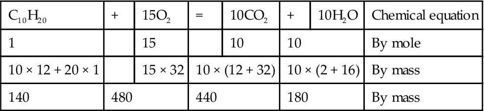
The stoichiometric fuel air ratio, where all the atmospheric oxygen would he consumed, is then easily derived. The required number of moles of air is evaluated, and then converted to mass. This is shown below using the molar oxygen content of air, and then the molecular weight of air:
15 × (1/0.2095) = 71.6 Number of moles of air
71.6 × 28.964 = 2073.8 Mass of air
140/2073.8 = 0.0675 FAR by mass
In fact the chemical reaction is far more complex with many reactions taking place simultaneously. This includes the above for the whole range of hydrocarbons present, as well as formation and consumption of carbon monoxide and oxides of nitrogen (NOx). The last is due to dissociation of atmospheric nitrogen.
Direct Firing and Indirect Firing
The vast majority of gas turbine engines employ direct firing where the fuel is injected into the engine combustion chamber and then burned. This is the case for the three primary fuels: kerosene, diesel, and natural gas, and also for a number of less common fuels.
However, for certain obscure fuels considered for industrial engines direct firing may not be practical due to their corrosive or erosive nature. The only manner in which such fuel may be utilized is via indirect firing where it is burned external to the gas turbine, with a heat exchanger to transfer heat to the compressor delivery air. Another indirect firing case of interest is a nuclear powered closed cycle.
For indirect firing the following changes must be made to performance calculations:
• No mass of fuel is added in the combustor calculations.
• CP downstream of the combustor is that for air at the given temperature, as opposed to that of combustion products.
The impact of both of the above is to lower power output and thermal efficiency since the mass flow and CP in the turbines are both lower. The exact power loss depends upon the engine cycle, and is between 4 and 8%.
Kerosene
Kerosene is a faction of crude oil primarily comprising a band of hydrocarbons with an average composition of C12H23.5 and molecular weight of 167.7. There are a number of commercial grades available such as JP4, JP5, Jet Al, and AVTUR that are refined to a tight specification. The proprietary high cost JP10 is a high-density fuel used for certain military applications such as missiles. The term kerosene is usually also taken to encompass the tighter faction aviation gasoline, or AVGAS.
Aeroengines almost exclusively use kerosene as its high calorific value minimizes fuel weight, and because it is free of corrosive elements such as sulfur, which is essential for such high cost engines. The premium in fuel price is warranted by these gains.
Diesel
Diesel fuel is a heavier faction of crude oil than kerosene, again comprising a band of hydrocarbons, with an average composition of C12.9H23.9 and molecular weight of 178.6. It is less refined and hence has a lower cost, but therefore also contains small percentages of other elements such as the corrosive agent sulfur. The terms diesel and fuel oil are commonly used interchangeably. There are a number of grades spanning Number 1 fuel oil to Number 6 fuel oil, the tolerance relative to the nominal specification for each grade is significantly wider than for the kerosenes. The lower Numbers are closer to kerosene, have lower amounts of sulfur (typically up to 1.5% by weight being acceptable), and hence usually only Numbers 1 and 2 are used for gas turbine engines.
For cost considerations, diesel is almost exclusively used for marine engines, and in military applications it presents a lower risk of explosion. Its corrosive sulfur content is less of an issue, since marine engines must be designed to withstand a corrosive atmosphere anyway due to the seawater environment.
Though land-based power generation engines usually burn natural gas, a back-up liquid fuel capability is often required to guard against an interrupted gas supply. In addition some niche applications use only liquid fuel. Again, due to cost, fuel oil Numbers 1 or 2 are employed, but life is shorter than for natural gas.
Natural Gas
Natural gas comprises over 80% methane with minor amounts of ethane, propane, butane, and heavier hydrocarbons. It may also include carbon dioxide, nitrogen, and hydrogen. There are a plethora of blends of natural gas available worldwide. The composition on a molar basis of a common blend, used as a “typical” natural gas for deriving gas properties of combustion products, is listed below:
| Methane: | 95% | I-Pentane: | 0.1% |
| Ethane: | 1.9% | N-Pentane: | 0.1% |
| Propane: | 0.5% | Hexane | 0.1% |
| I-Butane: | 0.5% | Nitrogen: | 1.5% |
| N-Butane: | 0.1% | Carbon dioxide: | 0.2% |

As stated, industrial engines for power generation predominantly use natural gas. This is because of its abundance, competitive cost, and negligible content of corrosive elements such as sulfur. The benefits include lower emissions of carbon dioxide and good engine life, and the large volume required is not a logistics issue as it is for aircraft or marine propulsion. The lower emissions of carbon dioxide are because the lighter hydrocarbons contain more hydrogen and produce more water and less carbon dioxide when burned. As described later the higher water content of the combustion products leads to a higher power output and thermal efficiency for a given engine and SOT level. Engines for natural gas pumping burn solely the gas tapped off the pipeline.
Liquefied petroleum gas (LPG) may be burned in gas turbines, injected either as a liquid or as a gas. Refinery tail gases are also of interest, and are produced as a by-product of oil refining. Other gas fuels occur naturally in lower quantities, such as condensates and naphtha. Their composition does not comprise the high percentage of methane present in “natural gas” and their properties provide significant difficulties for satisfactory fuel injection. For instance, condensates condense into a liquid at ambient temperature under the action of pressure.
Other Fuels
For industrial engines other fuels have been considered for specific applications/projects, but none have managed to take a significant share of the market.
Extensive efforts over many decades have been spent on developing coal as a fuel for gas turbine engines; however, to date success has been limited. Coal gasification involves pyrolysis of coal in an atmosphere of steam and usually oxygen (as opposed to air). The resultant fuel comprises primarily carbon monoxide and hydrogen, with minor amounts of carbon dioxide, methane, and sulfur compounds. Other attempts have also been made to coarse mill the coal to around 1 mm particles and then chemically clean it to remove the corrosive and erosive elements such as sodium, potassium, vanadium, and ash (silicon-based compounds). It is fine milled to sub-10 μm particle size such that it has characteristics of a gas for direct firing.
Hydrogen has been considered on a research basis for aircraft engines due to its high calorific value by weight. However, the volume of fuel required is prohibitive, requiring complex tank arrangements. Hydrogen is present in many blends of natural gas; too high a content leads to problems with fuel injector flow number.
Biomass is a gas fuel produced from natural vegetation. While it has been considered more recently as a renewable fuel it is not widely used due to the large area of cultivated land required to fuel one engine continuously.
Database of Key Fuel Properties for Performance Calculations
This section presents descriptions of the key fuel properties for performance calculations, together with a database. There are many other properties essential to gas turbine design, such as volatility and cloud point, which are outside the scope of this book.
Calorific or Heating Value on a Mass or Volumetric Basis
Calorific value is the heat energy released per unit mass of fuel burned as shown by Formula F7.1. Gross calorific value, or higher heating value (HHV), is the total heat released making no allowance for the latent heat required to vaporize the liquid water produced by the combustion process. Hence it is a theoretical parameter and is rarely used. The net calorific value, or lower heating value (LHV), does account for the latent heat of vaporization and hence is the parameter most commonly used for gas turbine performance calculations. Strictly LHV is quoted as the heat released under pressure in a constant volume when the combustion products are cooled to the initial temperature of 25°C. Hence for exhaustively rigorous combustion calculations the enthalpy balance should include:
• Heat release/absorption to raise fuel to 25°C
• Heat release due to reducing compressor delivery temperature to 25°C
• The resultant heat from the above is that available to raise combustion products from 25°C to combustor outlet temperature
Occasionally for gas fuels calorific value is quoted on a volumetric basis (Formula F7.2) having units of either kJ/m3 or kl/scm. The scm (standard cubic meter) is the amount of gas that would occupy 1 m3 at the ISO pressure and temperature of 101.325 kPa and 288.15 K respectively. Formula F7.3 shows how the number of scm present in a volume of gas fuel at any given pressure and temperature may be calculated.
LHV is used in most performance calculations such as design point, off design and test data analysis. Nominal values for the three primary gas turbine fuels are presented below, followed by methodologies for deriving values for a specific batch of fuel used during an engine test.
Liquid Fuels
The most accurate method is to measure LHV by testing a sample in a bomb calorimeter, and is normal practice for performance testing.
Natural Gas
For key performance tests using natural gas the fuel composition must first be determined using a gas chromatograph. The formula for then calculating LHV is complex, being a function of the wide range of constituents. Natural gas LHV can also be measured using a bubble calorimeter; however, this is only undertaken for “guarantee” performance tests as a further check on the calculated value.
Density and Specific Gravity
Fuel density, the mass of fuel in a given volume (Formula F7.4), is important during engine performance testing. Invariably volumetric flow rate is measured and density must be derived such that heat release may be calculated. It is not of interest for other gas turbine performance topics.
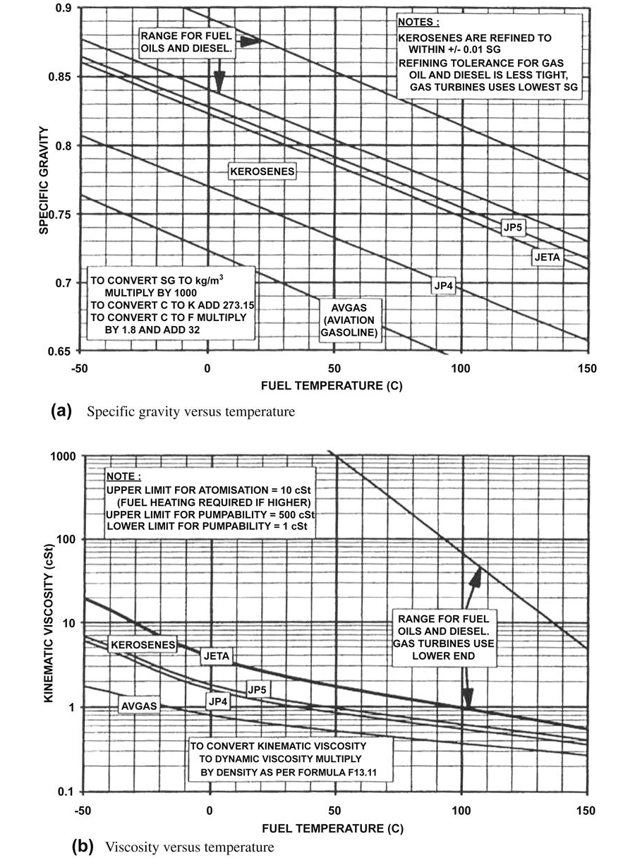
Specific gravity is commonly used for liquid fuels and is the ratio of the fuel density to that of water at 4°C as shown by Formula F7.5. Figure 7–22 presents SG versus fuel temperature for commonly used kerosenes and diesels. At 15°C the SG for AVGAS is 0.704, the rest of the kerosenes are between 0.76 and 0.818, and diesels range from 0.82–0.88. For a given kerosene type the tolerance is around ±0.1 and for diesel it is even wider. Hence Figure 7–22 can only be used as indicative of SG level and for key engine performance tests it must be measured. This is accomplished using a fuel sample in a laboratory with a calibrated hydrometer. The fuel sample temperature must be measured simultaneously and Formula F7.6 is used to derive SG at the fuel temperature measured during the engine performance test.
Gas fuel density may be calculated from Formula F7.7 where the “compressibility” term z is used to modify the perfect gas law such that it may be applied to non-perfect gases. Gas fuel pressure and temperature must be measured in the vicinity of the turbine flow meter. ASME (1993) Performance Test Code PTC–22 and ASME (1969) Gaseous Fuels PTC 3.3 show how R and z may be derived once the fuel gas composition is known. The calculation process for the latter is complex; however, if it is not followed then significant errors will result.
Viscosity, Dynamic and Kinematic
Dynamic viscosity is the resistance to movement of one layer of a fluid over another and is defined by Formula F7.8. Kinematic viscosity is dynamic viscosity divided by density (Formula F7.9) and is the ratio of viscous forces to inertia forces. Dynamic viscosity for liquid fuels is occasionally required for performance calculations in determining fuel pump power requirements such as during start modeling. Kinematic viscosity is a second-order variable in the calibration of bulk meters and turbine flow meters for measuring liquid fuel volumetric flow rate.
Figure 7–23 presents kinematic viscosity for gas turbine liquid fuels. It is common practice to arrange fuel dynamic viscosity as an input value to a performance computer program. Hence suitable values may be taken from Figures 7–22 and 7–23. If necessary the reader may “fit” a polynomial to the data presented in these charts to embed the properties within the computer program.
Liquid fuels are not “pumpable” with a kinematic viscosity of less than 1 cSt, and atomization will be unsatisfactory above 10 cSt. Figure 7–22 shows that kerosenes generally have a viscosity of less than 10 cSt even at –50°C and hence are always acceptable for atomization. However, diesels do exceed the limit and hence fuel heating is required if its temperature is allowed to fall below the threshold level.
None of the above effects are of importance for gas fuel as its viscosity is an order of magnitude lower; hence a database is not provided here.
CP of Fuels
For fully rigorous modeling fuel CP is required to calculate enthalpy input of the fuel prior to combustion. Approximate levels of CP for the primary gas turbine fuels are:
CP of Combustion Products
CP of the products of combustion is required for all performance calculations involving combustion including design point, off design, and engine testing.
However, this is not so for natural gas that may come in a huge variety of blends, often with more than 10 constituents. Where second-order loss of accuracy is unacceptable then the CP of the products of natural gas combustion must be evaluated rigorously for the given natural gas composition.
Synthesis Exchange Rates for Primary Fuel Types
Industrial engines may often operate on more than one fuel type; in fact many engines are capable of switching between natural gas and diesel fuel in the field. This allows operators to pay a lower tariff for the gas fuel due to an interruptible supply, but not lose any availability. Also, engines may often undergo a production pass off test on kerosene at the manufacturer’s facility, even though they will primarily operate on natural gas in the field.
Hence the second-order effect on engine performance of the different fuel types is often of great interest. The major contributor to performance change is the change in gas properties downstream of the combustor. Any difference in fuel mass flow resulting from different calorific values, and change in referred parameter turbine maps (full non-dimensional maps are unchanged), produces only tertiary effects.
Kerosene to Diesel
The gas properties of the combustion products of kerosene and diesel, as well as their lower heating values are very similar. Hence there is negligible change in performance when burning either of these fuels.
Liquid Fuel to Natural Gas
The CP of the combustion products of the natural gas is around 2% higher than for liquid fuels. This has a noticeable impact upon performance increasing both the fuel energy flow required for a given combustor temperature rise, and the shaft power output. The net effect is an improvement in SFC. The exact change in performance depends upon the engine cycle but at constant SOT the changes when burning gas relative to a liquid fuel are in the range:
Oil Types and Database of Key Properties
Oil Types
Oils used for gas turbine engines fall into two major categories: mineral oils and synthetic oils. Mineral oils result from the refining of crude oil. Usually anti-oxidant and anti-corrosive additives are employed for gas turbine use. Synthetic oils are ester based and their cost is approximately 10 times that of mineral oils.
Synthetic oils are used almost exclusively in gas generators due to their vastly higher auto-ignition temperature. Mineral oils are usually used for industrial power turbines where bearing chamber temperatures are sufficiently low. This is particularly true where journal as opposed to ball bearings are used, because the former requires approximately 20 times the oil flow to dissipate the heat resulting from significantly higher friction, hence the cost of using synthetic oil is prohibitive. Journal bearings are often required in large power turbines as they are capable of reacting far higher thrust loads.
Density
Formula F7.10 enables oil density for a typical synthetic oil with a density of 1100 kg/m3 at 15°C to be calculated as a function of oil temperature. The same formula may be factored to give the typical density of a mineral oil at 15°C, and then used for other oil temperatures. Typical values for oil density at 15°C are:
Viscosity, Kinematic and Dynamic
Kinematic and dynamic viscosity were defined earlier. Oil viscosity is important for calculating bearing and gearbox losses.
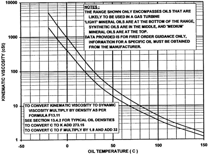
Figure 7–23 presents kinematic viscosity versus temperature for oils typically used in gas turbines. Light mineral oils are at the lower end of the band, synthetic oils in the middle and medium mineral oils at the top.
The formulae presented provide sufficient accuracy for all performance calculations.
Formulae
F7.1 Fuel lower heating value (kJ/kg) = fn(heat release (kJ), fuel mass (kg))
F7.2 Fuel lower heating value by volume (kJ/m3) =fn(heat release (kJ), number of standard cubic meters of gas fuel (m3))
F7.3 Standard cubic meters (m3) = fn(volume (m3), gas fuel pressure, and temperature (kPa, K))
This calculates the number of standard cubic meters that are equivalent to the amount of gas occupying the current volume at the prevailing P and T.
F7.4 Density (kg/m3) = fn(mass (kg), volume (m3))
F7.5 Fuel specific gravity = fn(actual density (kg/m3), standard density (kg/m3))
The standard density of 1000 kg/m3 is that of water at 4°C.
F7.6 Fuel specific gravity = fn(fuel sample SG, fuel sample temperature (°C), fuel temperature (°C))
“Sample” refers to a fuel sample for which the SG and temperature have been measured in a laboratory.
To convert from FSG to actual density multiply by 1000 kg/m3.
F7.7 Gas fuel density = fn(static pressure (kPa), gas constant (J/kgK), temperature (K), compressibility)
F7.8 Dynamic viscosity (Ns/m2) = fn(shear stress (N/m2), velocity gradient (m/sm), static temperature (K))
Fshear is the shear stress in the fluid. V is the velocity in the direction of the shear stress. dV/dy is the velocity gradient perpendicular to the shear stress.
F7.9 Kinematic viscosity (cSt) = fn(dynamic viscosity (Ns/m2), density (kg/m3))
F7.10 Oil density (kg/m3) = fn (oil temperature (K))
This is for a typical synthetic oil.
F7.11 Average molecular weight of combustion products = fn(molecular weights of constituents, number of moles of constituents)
Unconventional Fuels
Unconventional means different things to different people. Today, end users, with the OEMs’ cooperation, are burning biowaste, paper production waste liquor, pulverized coal gas, low BTU waste (from plastics manufacture) hydrocarbons, and a variety of other “emerging” fuels.
What follows are extracts of recent studies conducted by an EPC contractor4 and a gas turbine OEM,5 both of which discuss different aspects of the use of unconventional fuels and contrast that with use of natural gas. The equipment supplied by an OEM of fuel treatment systems (Westfalia) is also discussed.6 Further, the authors of these works represent engineering (the EPC contractor), economics and logistics/global project finance (the OEM in concert with the World Bank), and accessory system design (Westfalia Separator makes treatment systems for fuel and systems that support the fuel system). The reader needs to note the different emphases placed on the same system with the same fuel, by these different technical and corporate functions.
Emerging Fuel Trends/New Fuel Technologies
The fracking movement has generated much controversy in the USA. The natural gas it yields may vary somewhat in its extent of impurities and geological “additives,” but it is still natural gas. The process has opened up natural gas reserves that were previously unattainable. Other countries and continents are sure to follow. The potential problem is that with fracking, oil and gas companies may opt to use contractors. Contractors do not always use the same safety standards to which a major oil company may be held. Therefore “results” with respect to work items such as getting rid of associated waste water (and associated impurities) varies.
With fracking, the oil and gas companies saw a potential for subcontracting work. Employing contractors to drill into natural gas-rich formations, then create the “minor” explosions that break up the rock to the extent that the ground releases its entrained natural gas, then inject the fluid mix that moves the gas to the wellhead at the surface, is cheaper than the oil company doing it themselves. Their legal liability for what corners these contractors may cut may be less than had they done it themselves.
Fracking technology is reasonably well thought out. A casing sheath is supposed to protect surrounding rock and soil formations, as well as ground water sources, from being contaminated with the potentially poisonous mix of drilling fluid (water plus chemical additives). Sheath ruptures and punctures happen. This book shall not attempt to debate how often.
The risk, even were the technology perfect, is evident and its chances of increasing with smaller contractors who may feel they have to cut corners must be acknowledged. Will fracking be more competently done by seasoned oil and gas companies than contractors? Probably yes, they have the resources, the experience, the safety standards. Also their liability exposure is greater and they have much to lose if they can be found to have cut corners.
All this said, the bottom line is that gas prices dropped as a result of the increased production from fracking. In 1997, the known global gas reserves stood at 70 years' worth; coal at 200. A decade later, known gas reserves had increased, thanks to new exploration and improved deep sea drilling methods that attained depths that were formerly unknown.
However, even with a world giddy with the thought of more natural gas, coal refuses to go away. It won’t disappear, even in the gas turbine world, and even in countries that are more heavily legislated with respect to emissions. The reason is advancing technologies with respect to coal as a gas turbine fuel, the capture of carbon-in-fuel or CO2 resulting from coal combustion and the storage of CO2. These technologies either permit or promise the potential of reducing the GHG emissions. The emphasis on this element of running turbines has grown considerably in terms of importance placed on it by OEMs and legislators.
This is interesting in places like the USA where some plant owners have not just converted their steam turbines to combined cycle operation that burns natural gas, but also converted their steam turbines to burn natural gas, without any modifications to the steam turbine that may also raise its effieiency. Conventional wisdom dictates that operators take up base load with a steam turbine, then use gas turbine(s) for peaking, but there have been cases of operators doing the reverse, probably hoping to reduce their on-record emissions.
Coal has been used as a gas turbine fuel in liquefied form and also in pulverized form. More recently, “syngas” from coal (consisted of CO and H2) has been explored. If one neglects impurities, then syngas can burn like natural gas (1 unit of CO2 per unit of syngas by weight).
Once a gas turbine has been modified to burn coal in any form, it can then spread its wings still further. Some OEMs have done work on buring biomass with DLN combustors.
Consider also that gas turbines, in combined cycle or otherwise, can be modified to burn other unconventional fuels. Flue gas from steel mills and other industries, waste liquids from petrochemical and plastics plants, black liquor from producing paper have all been used with varying degrees of success. Residual fuel is a popular fuel in some gas-poor countries as well, and this chapter deals considerably with the equipment and treatment required to successfully do this.
Returning to the subject of coal as a potential turbine fuel: many operators globally have operated steam turbines to supply the bulk of their power and gas turbines run on LNG (if they have no gas resources, like Japan) to fill in peaking demands. What this created in some countries, like China and Japan, is the drive to work with supercritical, ultra-supercritical (USC) and now advanced ultra-supercritical steam. The EU and the USA now have research programs of their own. Siemens won the EU grant to work on advanced steam turbine metallurgy research, but that program has run (maybe temporarily) out of money. The US DOE continues its work to explore boiler materials that will operate with 700°C temperature and over steam.
There have been some interesting studies of systems that integrate the heating and cooling streams from gas and steam turbines (see Chapters 10 and 12). Consider also that the Benson boiler design common in most GT CCs is essentially the same boiler design (neglecting scale) as is used with steam turbine cycles. The potential for cycle adaptation for fossil fueled turbines abounds.
IGCC is one of the most studied systems for using coal (PC) fuel in GTs. This chapter has more material on that technology. Oxy-combustion and hydrogen fuel are two other fuel technique/fuel systems being actively explored.
Oxy-combustion has now replaced IGCC as being the intended combustion technique to be used in Illinois’ FutureGen project. Discussion on both oxy-combustion and hydrogen as a fuel has been addressed in Chapter 18, the Future of Gas Turbines, as these are fuel fields still in their relative youth.
All coal-fueled power plants are either using or planning carbon removal, then carbon sequestration and storage (CSS) systems. These are discussed in Chapter 11 (on emissions).
Economic Conditions that Affect Fuel Strategy
In the 2007 economic climate of rocketing natural gas prices, nonconventional fuels are more important than ever. Even when global politics stabilize, because fossil fuel deposits are finite, nonconventional fuels will tend to transition into “conventional.” Let us first consider the market conditions relevant to fuel selection in gas turbines and their operating environment and how these may affect the various sectors of the gas turbine environment.
Market Demand7
Contract awards for the last five years for fossil fuel-fired power plants (above 50 MW) averaged 63 GW per year, sales are forecasted to average about 67 GW per year over the period 1999–2004. From a regional viewpoint, the market in the Asia Pacific Basin is declining, while showing a moderate growth in Europe (starting from a low level) and strong growth in North America. This is reflected in the growth of the 60 Hz market. In the past, the proportion of power plants with gas turbines, that is, open cycle and closed cycle (combining gas and steam turbines), was around 54% of total fossil-fuel-fired power plants. For the next five years, this proportion is expected to rise to 63%. For open- and closed-cycle power plants, this means that sales are expected to grow from 34 GW per annum to 42 GW per annum. This growth is predominantly due to market developments in North America.
In comparison with coal-fired power plants, open- and closed-cycle power plants are characterized by lower investment costs. On the other hand, fuel costs (i.e., fuel price and plant efficiency) play a relatively more important role. Therefore, gas pricing is a very important issue, which ranges presently from about $2.0/GJ to $4.5/GJ, with the North American prices being at the lower end of the range. Thus, particularly in North America, open- and closed-cycle power plants can be particularly attractive investments.
Technology, Performance, Environment, and Design Trends
Over the last 50 years, the efficiencies of gas turbines went up from 33–38% (LHV) and the efficiencies of combined-cycle plants from 48–58%. At present, there are a rather small number of global manufacturers and suppliers offering GT products covering a wide range of power output. The products of the different suppliers can be grouped in clusters by comparable output. A rough classification is small (S), that is, up to 50 MW; medium (M), above 50 MW; and large (L), which is the class of the largest, high-performing heavy-duty gas turbines in the market with a power output above 200 MW. For all major manufacturers, the small and medium classes include proven existing GT models with lower efficiencies and operating temperatures but with robust and reliable performance; the large classes are confined to high-performance machines.
The latest gas turbine technology also reflects the expertise of aero-jet engine manufacturers. As a result, using pressure ratios of around 17, performance features have been achieved for heat rates in the range of 9400–9800 kJ/kWh and for efficiencies up to 38%. These performance improvements have been achieved through improved compressor design; higher turbine inlet temperature (approximately 1250°C ISO); advanced blading (design, materials, coating); optimal design of the turbine blade cooling system, with or without the need for external coolers; improved cooling of the combustion system sections (chamber, canes, transitions); and less pressure drop in the turbine exhaust.
Less than 25-ppm NOx emissions can be expected from these machines. This compares with the maximum allowable levels of 60 ppm for GTs fired with natural gas as set out in the World Bank’s “Thermal Power-Guidelines for New Plants.” Because of better materials (alloys and coatings), with a higher resistance to high temperature oxidation and corrosion, combined with better cooling techniques, gas turbines are expected to reach a unit capacity of around 250–350 MW and GT efficiencies of 40% over the next years. In conjunction with optimized main steam parameters and improved plant component efficiencies, this in turn will increase the CC plant capacity into the 375–500 MW range, with CC efficiencies around 60%. (See also Figure 7–24.)
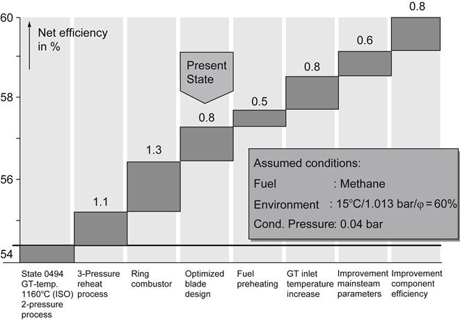
From a plant aspect, plant construction time has been shortened by the concept of predesigning, introduction of modules, and advanced project management and logistics. Inter alia, this was effected by simplification of the electrical and I&C systems as well as the foundation and overall civil works construction requirements. In addition, plant operation has been simplified, for example, by allowing full 100% steam bypass operation in the event of steam turbine malfunctions.
Cost Trends
Typical combined-cycle blocks are roughly in the range of 50–500 MW and costs range from $500–750/kW.
Impacts on Design and Manufacturing in Developing Countries
Table 7–1 shows the cost breakdown for combined-cycle plants (350–700 MW capacity) based on Siemens experience into the following categories: integrated services (project management/subcontracting; plant and project engineering/project management software, plant erection/commissioning/training; transport/insurance) and lots (civil works; gas- and steam-turbine and generator sets; balance of plant; electrical systems; instrumentation and control systems; and the boiler island). Up to approximately 25–35% of the costs of CC plants can be provided locally in countries such as Argentina, Brazil, China, India, Malaysia, the Philippines, South Africa, and Thailand.
TABLE 7–1
Cost Breakdown for CC Power Plants
| Integrated Services | 4% | Project Management/Subcontracting |
| 2% | Plant and Project Engineering/Software | |
| 8% | Plant Erection/Commissions/Training | |
| 1% | Transport, Insurance | |
| Σ15% | ||
| Lots | 15% | Civil Works |
| 32% | Gas- and Steam Turbine Set | |
| 16% | Balance of Plants | |
| 7% | Electrical Systems | |
| 4% | Instrumental and Control | |
| 11% | Boiler Island | |
| Σ85% | ||
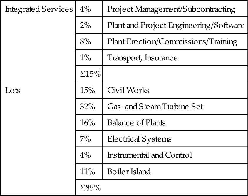
Basis: 350/700 MW CC Plant with a V94. 3A Gas Turbine
(Source: Siemens.)
These include some of the engineering services (project engineering/project management as well as plant erection/commissioning) as well as some or all of the following lots: civil works, balance of plant, electrical systems, and the boiler island.
Upgrading Fossil-Fueled Power Plant
The preceding descriptions of technology developments have been confined to “Greenfield” plant installations. However, in many cases the power plant operator looks to improve plant performance beyond what can be achieved through routine maintenance; in particular, the operator desires higher output, additional heat extraction, improved pollution control, and improved plant control. A common approach to this problem is to incorporate a gas turbine into an existing fossil-fired steam generation system. The most common configuration (Figure 7–25) is called parallel powering, where the gas turbine exhausts are used in the existing steam cycle. This is achieved by feeding the exhausts into a heat-recovery steam generator (HRSG), which provides additional steam to the existing steam turbine. Typically, parallel powering requires the addition of a gas turbine, associated electrical and instrumentation, and control equipment, civil engineering, HRSG, additional piping and pumps as well upgrading the steam turbine. Generally, parallel powering can be undertaken fairly separately from the existing part of the plant, with a final integration phase and a plant downtime of 1.5–2 months. The typical cost range is $300–500/kW.
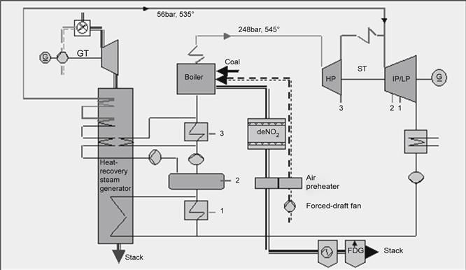
Physical Properties that Affect Fuel Selection and System Design
Gas8 fuels are more suitable than liquid fuels for continuous base-load operation. Gas turbine combustion system design reflects this fact. Burning natural gas in a premix mode is the most efficient fossil fuel technology with the lowest emissions.
A wide range of other gaseous fuels can also be used in gas turbines. Table 7–2 shows other gaseous fuel types and their impact on gas turbine design.
TABLE 7–2
| Fuel Types | Leading Property | Lower Heating Value (BTU/scf) | Impact on Fuel System Designs |
| Natural gas | Basic fuel | 800–1200 | Basic design |
| Process gases | Low heating value (large volume flow) |
||
| 100–150 | Increased compressor flow | ||
| Syngas | 200–400 | Configuration of fuel supply system combustors | |
| Low BTU natural gas | 400–800 | ||
| Liquefied petroleum gases Other gaseous fuels |
High heating value (low volume flow) |
2300–3200 | Configuration of fuel supply systems, combustors. Special constraints for startup and part-load operation |
| Process gases Syngas |
High hydrogen content | 300–1000 | High flame velocity, special material, safety issues |
| Gases with heavy hydrocarbon content | High dew point | Formation of droplets, erosion, nonhomogeneous composition, variable heat flow |
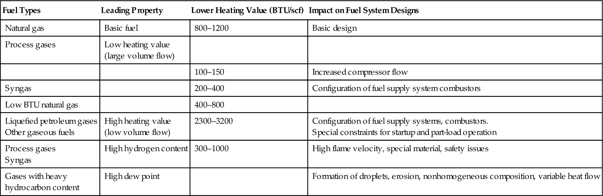
Fuels Rich in Hydrogen
Hydrogen (H2) characteristics differ substantially from those of natural gas. H2 exhibits low ignition energy, low molecular weight and density, and high flame temperature and propagation speed. Since H2 has the ability to diffuse through and embrittle materials, the gas turbine itself and ancillary systems must allow for this fact.
For H2-rich fuels, the combustors are particularly susceptible to premature ignition. Their design must avoid flashback by accelerating the fuel flow through burner passages while avoiding nozzle erosion caused by H2’s high-speed flame. The diffusion combustion must use substantial amounts of steam cooling diluents for NOx reduction because of the high flame temperature. Therefore, the combustion products have a high moisture content and a heightened heat transfer capability, which affect the life of hot-gas-path components. So the use of gaseous fuel with high H2 content (above 50% volume) is currently limited to firing temperature typically found in older E-class gas turbine technology.
However, several combustion testing facilities are working on studying the behavior of full-scale combustor operation for F-class technology at firing temperatures and at actual operating pressures and flows. In several IGCC plants, fuel with more moderate H2 content (between 20 and 30%) is combusted in diffusion mode at F-class firing temperature. Development of dry low NOx combustors operating with higher than 10% H2 content (the present maximum allowable concentration) will be a major breakthrough.
From both the end users’ and the EPC contractors’ perspective, the use of H2-rich fuels presents many challenges, such as providing a different startup fuel capability, ensuring adequate purging systems to cope with much larger fuel handling systems volume (low BTU value), and dealing with stringent safety issues for leakage detection, explosion-proofing, ventilation, and so on. Special consideration should be given to materials of construction for pipes and valves as well as welded connections and sealing materials.
One EPC contractor’s (Bechtel) experience with medium H2 content fuel is at Tampa Electric Company’s Polk Power Station Unit 1, an IGCC plant with a syngas fuel content of approximately 37% H2 by volume at a lower heating value (LHV) of 200 BTU/ft3 (20% of the natural gas LHV).
Liquefied Natural Gas
To supply natural gas from the extraction fields to end users over large distances or oceans, the most common method is to liquefy the natural gas by refrigeration at –160°C (256°F) and then transport it in spherical tankers. At the receiving terminal, the liquefied natural gas (LNG) is unloaded and stored in insulated tanks. From the storage tank, the LNG is pumped at the desired pressure and vaporized for use in gas turbines. The combustion of vaporized LNG in a gas turbine is not much different than that of regular pipeline-quality natural gas in gaseous form. The use of LNG can be noted in many Asia-Pacific countries, where local natural gas resources are scarce.
It is expensive and therefore is used in countries such as Japan, which also has higher emissions standards than those in the rest of SE Asia.
Based on at least nine major projects, one major EPC contractor’s experience shows that integration of the LNG unloading, storage, and regasification facilities with the associated combined-cycle power plant yields substantial advantages to the owner. Sizable cost savings can be achieved by developing common auxiliary systems for cooling water and fire protection, by optimizing the site layout, and by integrating the unloading pier with power plant water intake and discharge structures.
A special feature of integration of the two facilities (LNG terminal and power plant) is the recovery of LNG cold energy from regasifying the LNG. In the past, the regasification was done by heating with seawater using open rack vaporizers without the heat. For the integrated system, one patented process uses a glycol-water mixture as the working fluid, which is cooled to 1°C in a closed-loop LNG vaporizer heat exchanger. The cold glycol water is then sent to the gas turbine to cool the gas turbine inlet air to 7°C. A fin-tube-type air-cooling coil is located downstream of the air filters. The return glycol water is pumped back to the LNG terminal, where it passes through a seawater heat exchanger to add supplemental heat as needed. Following the return of the warm glycol-water working fluid, the regasification process starts over again. Figure 7–26 illustrates the benefits of inlet cooling.
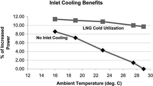
Liquefied Petroleum Gas
Liquefied petroleum gas (LPG) typically consists of butane and/or propane. LPG is a natural derivative of both natural gas and crude oil. Since LPG is composed mainly of heavier hydrocarbons, the gas turbine combustion system operates quite differently than for LNG. As the price for butane and propane varies seasonally, the receiving terminal should be designed to receive LPG in any combination of the two hydrocarbons, from 100% propane to 100% butane.
LPG is not widely used as a fuel for gas turbines because of its limited availability and the complexity of the fuel handling equipment. In terms of phase change properties at atmospheric pressure, propane is liquid at –42°C (44°F) and butane at 0°C (32°F). For use in gas turbines, the LPG is supplied at 90 bar (1300 psi); at this pressure, it can easily change phase between liquid and gas. One result of LPG’s volatility is that gas turbines can operate in only two modes, either “on” at full load or “off” at full speed, no load. With LPG supplied as 100% liquid at a lower pressure and with careful temperature control, gas turbine operation across the entire range of loads is possible. The limited market for LPG has kept manufacturers from developing dry low NOx combustion systems for this fuel. The use of conventional diffusion burners necessitates the use of diluents to meet emissions limits, which affect the equipment life and increase the cost of the water treatment plant.
LPG vaporization can be also used to cool the air inlet to the gas turbine in the same way as LNG cold utilization. The economics of the inlet chilling systems, however, are quite different due to the diverse cryogenic properties of pentane and butane.
Today dimethyl-ether (DME) manufacture is commercialized. DME, which is interchangeable with LPG, can be manufactured from multifeedstocks such as coal, natural gas, and biomass in the same way as methanol. Table 7–3 lists properties of DME in comparison with butane and propane.
TABLE 7–3
Selected Dimethyl-Ether Properties [7-1]
| Property | DME | Propane | Butane |
| Boiling point (°C) | –24.9 | –42.1 | –0.5 |
| Vapor pressure at 20°C (bar) | 5.1 | 8.4 | 2.1 |
| Liquid density at 20°C (kg/m3) | 668 | 501 | 610 |
| Specific density (gas) | 1.59 | 1.52 | 2.01 |
| Low heating value (MJ/kg) | 28.4 | 46.4 | 45.7 |
| Autoignition temperature at 1 bar (°C) | 235–350 | 470 | 365 |
| Explosion/flammability limit in air (volume %) | 3.4–17 | 2.1–9.4 | 1.9–8.4 |
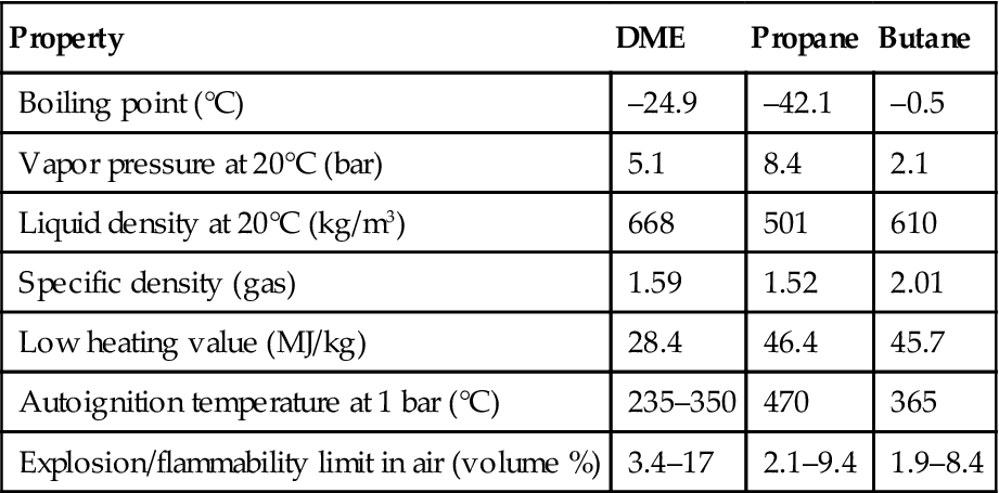
This multipurpose fuel is very attractive for developing countries (China, India) in permanent need of portable (bottled) or easily transportable fuels. OEMs (GE in particular) are looking at commercial offerings of DME-fired E- or F-class heavy-duty turbines. In Japan, the DME forum (JDF), formed in 2000, with 37 Japanese companies and two universities as members, works to ensure large-scale DME technology development. With low emissions and good thermal efficiency, DME could play an important role in specific power generation markets.
Fire detection and protection systems must be designed to allow for the fact that LPG and DME are heavier than air. Further, the fuel treatment system requires (1) fuel preheating to ensure that the fuel temperature is maintained above its dew point at all times and conditions and (2) proper handling and storage of the fuel.
Syngas and Other Low-Btu Gases
Gasification of coal and other low-grade fuels to produce syngas enables more efficient use of these fuels through IGCC technology. Over 40 projects worldwide (existing or in development) use heavy oil, petroleum coke, coal, biomass, and waste materials as fuel. The capital cost continues to drop as a result of technological advances and incorporation of lessons learned from existing facilities. Under the generic name of low-BTU gases, these fuels can vary significantly from one application to another and are highly dependent on the type of feedstock and gasification process. Table 7–4 summarizes some of the low-BTU gases based on hydrogen content and the range of LHV.
TABLE 7–4
| Gas Source | H2 Content | LHV (BTU/scf) | Remarks |
| Oxygen-blown gasification | Above 30% volume | 200–400 | Steam injection for NOx control |
| Air-blown gasification | 8–20% volume | 100–150 | Very large fuel systems |
| Blast furnace | Less than 100 | Must be mixed with other fuels, usually natural gas | |
| Coke oven | Very high value above 40% volume | Requires “scrubbing” before use in a gas turbine |
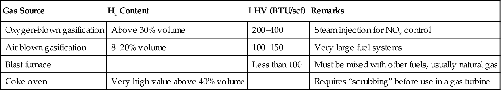
Conventional gas turbine combustion systems and associated fuel pretreatment apparatus cannot be used unmodified for these fuels. Since each fuel has different properties, analytical (mainly computational fluid dynamics; CFD) and experimental work is conducted before field implementation. Low-BTU gases on the combustion system necessitate full characterization of the combustor performance in test facilities. However, there is no substitute for actual field operational experience with each type of fuel. As a result, extended startup time is required to fine-tune the gas turbine fuel supply system. Table 7–4 illustrates the wide variety of low-BTU gases used in gas turbines.
The Wobbe Index (WI), a measurement of volumetric energy (calculated using the LHV and specific gravity of the fuel), indicates a combustor’s capability to burn different types of fuels using a unique fuel supply system. Usually, the maximum allowable WI variability is around ±5% of its value. Beyond this limit, multiple gases can be combusted in the same gas turbine only if supplied by independent fuel trains with different control valves, manifolds, and fuel nozzles, which add complexity and cost. Table 7–5 depicts the composition of low-BTU gases in comparison with natural gas. The LHV and WI are calculated as a percent of their absolute values for natural gas.
TABLE 7–5
Typical Syngas Fuel Composition [7-1]
| Syngases | H2 | CO | H2O | N2 | CO2 | CH4 | C2+ | LHV as % of Natural Gas LHV |
Wobbe as % of Natural Gas WI |
| 1 | 31.25 | 29.78 | 34.59 | 0.98 | 3.27 | 0.13 | 0 | 22.62 | 16.96 |
| 2 | 9.03 | 16.25 | 5.46 | 40.56 | 13.61 | 14.6 | 0.53 | 16.39 | 17.06 |
| 3 | 9.56 | 9.61 | 29.55 | 22.42 | 7.48 | 20.73 | 0.54 | 22.91 | 21.62 |
| 4 | 0 | 0 | 32.6 | 11.72 | 8.38 | 44.64 | 2.65 | 32.32 | 37.84 |
| 5 | 0 | 0 | 0 | 5 | 10 | 84.5 | 0.5 | 76.92 | 73.86 |
| Natural gas | 0 | 0 | 0 | 1.2 | 0.2 | 94.8 | 3.8 | 100 | 100 |
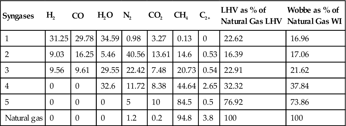
As shown in the Table 7–5, the LHV of syngas is lower than that of natural gas, requiring a considerable fuel mass flow increase to match the necessary heat input. When fully fired on typical syngas compositions, the gas turbine produces up to 25% more power than a conventional machine operating on natural gas, due to this increased mass flow.
In addition to the complexity of the combustion process related to the fuel composition, a major concern for gas turbines firing syngas is the significant amount of contaminants usually found in this type of fuel.
Deposits and Degradation
Certain deposits, especially from trace metals, affect gas turbine integrity and performance. In one particular application, Ni deposits concentrated on the tip of the burner forced a redesign of the burner. In many cases, the deposits plug the blades’ cooling holes and cause overheating as well as cracks in the material. Special coatings on the blades often are used to minimize the corrosion.
Performance Degradation
Another negative effect of deposits is the accelerated thermal performance degradation. Limits on the allowable degradation, recoverable and nonrecoverable from base load conditions can be provided by the OEMs. Operating below these limits will increase the risk of compressor surge. In the development phase of a project, the impact of the recoverable and nonrecoverable degradation, scheduled outages, and so on needs to be analyzed.
Global Experience with IGCC
As of 2004, 21 global integrated gasification combined-cycle (IGCC) power plants producing 5810 MW are in operation. GE heavy-duty gas turbines are used in or planned for some of these IGCC projects. These projects include various levels of integration within the gasification plant as well as a variety of fuel compositions. Siemens and Ansaldo (a Siemens licensee) are also active participants in this technology. Several units with silo combustors (V94.2) have been in operation for at least five years. MHI has entered the IGCC arena, using asphalt as the main feedstock and combusting the syngas in a modified M701F gas turbine. Table 7–6 lists gas turbines from various manufacturers currently being employed in IGCC plants.
Liquid Fuels
Light Distillates in Heavy-Duty Gas Turbines
Heavy-duty gas turbines are capable of burning a variety of liquid fuels ranging from light petroleum distillates to heavy residuals. The combustion process of light distillates such as naphtha, kerosene, and No. 2 fuel oil is well proven through millions of hours of operation. The real challenges for gas turbine design and operation come from the use of heavier ash-forming fuels. The combustion system capable must efficiently burn the fuel while maintaining emission limits and hardware integrity.
Residual Fuel
There is a glut of cheap residual fuel on the market. Countries like China are keen to use it. Even after the cost of transportation via tankers from the Middle East is added, it is still an attractive option for fast developing countries. Power generation is the largest industrial sector in China, which will grow to be the largest power producer in the world. A look at China’s environmental standards reveals that the Chinese are tightening their limits, but they still do not address CO2 greenhouse gas emissions, other than aiming for maximized fuel efficiency. For all other emissions, like NOx, if OEMs keep to best available technology (BAT), the environmental regulation targets are easily met.
The OEMs' response to their newly industrialized country (NIC) clients is predictable. When presented with a technical challenge, residual fuel or otherwise, they find a way to work with it. So, overall, residual fuel, with its resultant CO2 emissions that exceed those formed with natural gas combustion, will continue to grow in terms of usage. Not just gas- and oil-poor countries use it. One of Siemens’s most successful residual fuel plants is in Mexico. Some OEMs are doing interesting work on CO2 mitigation generally by postcombustion absorption, reinjection into rock formations (which they expect will hold the gas for some period of time), and similar initiatives. To this point, there has been no real breakthrough on this front.
Residual or “Bunker” Fuel Combustion9
Traditionally, older E-class technology gas turbines have been used for combusting crude oils, residue oils, and other heavy oils, since their firing temperatures are lower. Because the fuel is cheap, high efficiency is not an issue. However, the combustion of these fuels can prove extremely detrimental to gas turbine life due to corrosion, erosion, and fouling of the blades. Hot corrosion due to trace elements such as sodium (Na), potassium (K), lead (Pb), and particularly vanadium (V) in the fuel has a major impact on gas turbine performance and service life of hot gas path components.
Small amounts of V, naturally found in liquid fuels, create low-temperature-melting (1250°F) vanadium pentoxide (V2O5) ash. At typical gas turbine operation temperatures, these V ash deposits are in molten form and accelerate oxidation of turbine blades and vanes. The presence of other alkali metal contaminants in the fuel, Na and K salts, leads to formation of sodium sulfates (Na2SO4) (the sulfidation attack) through reaction with sulfur (S) in the fuel, resulting in pitting of the hot path components.
Fuel Specifications
Crude composition varies widely in terms of the amount of trace metal contaminants, ash, sulfur, and wax as well as physical properties such as viscosity, gravity, and distillation range.
OEMs have specifications for allowable levels of these contaminants in the fuel as well as the appropriate test methodology to determine them. Their concentrations might be corrected based on the actual LHV of the fuel.
Typical values are presented in Table 7–7.
TABLE 7–7
Limits of Major Contaminants in Liquid Fuels [7-1]
| Element | Units | Liquid Fuel Limits | Remarks |
| Vanadium (V) | ppm (wt) | Less than 0.5 | |
| Lead (Pb) | ppm (wt) | Less than 1.0 | No violation allowed |
| Sodium (Na) and Potassium (Ka) | ppm (wt) | Less than 0.5 | For coastal areas, even less. Also function of other additives |
| Ash | ppm (wt) | Less than 100 | Additives increase the amount of ash |
| Water | % volume | Less than 1.0 | Corrosion of fuel system components |
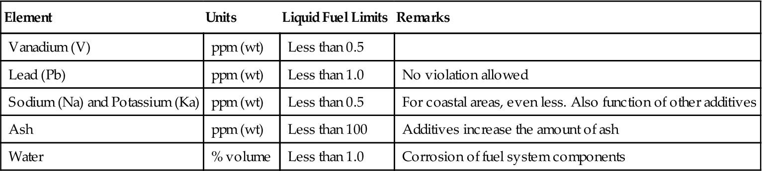
For crude fuels with a low flash point, the fuel system must meet explosion-proof design specifications.
Fuel Treatment Summary
Prior to combustion in the gas turbine, the fuel has to be pretreated to reduce the concentration of contaminants to meet the stringent requirements set in Table 7–7. The pretreatment process involves chemical reactions and mechanical cleaning systems.
Additives for Residual Fuel
Na and K salts are soluble in water and can be removed by on-site fuel washing. Other methods of fuel treatment include the use of high-temperature corrosion additives. Effective additives are tailored to a specific fuel composition. The most common additive is magnesium (Mg). Additives containing Mg are used primarily to control vanadium oxidation by increasing the ash melting point, allowing the ash to remain in a solid state on gas turbine blades and vanes. The melting temperature of the new ash compound, which contains Mg, V, and oxygen (O), is much higher (around 1238°C or 2260°F) and dictates the maximum allowable firing temperature of the gas turbine. Other additives, based on chromium (Cr) and silicon (Si), are used mainly to combat Na- and K-based contaminants.
Mg-based additives are generically of three types: water soluble, oil soluble, and oil dispersible. The water-soluble type is the cheapest; however, it requires extensive mechanical handling. Oil-soluble additives are the easiest to handle, since they are self-dispersing on line and off line in fuel storage tanks. However, they are five times more expensive than the water-based additive. Magnesium sulfate (MgSO4) is the most common water-soluble product using a 1:1 ratio for Mg:V. An example of oil-soluble product is KI 150 from Petrolite using a 3:1 ratio for Mg:V.
Mechanical System Functions
To reduce the amount of expensive additives, a preliminary step for improving fuel quality entails use of commercially available mechanical fuel treatment skids composed of centrifugal separators, pumps, and sludge tanks. The devices can reduce the concentration of Na, K, S, and V. A typical two-stage system can reduce the Na content from 150 ppm to 1 ppm for heavy salts. An alternative is the use of an electrostatic desalting system, where the water is coalesced to large droplets to enhance settling. However, electrostatic systems require longer startup time and more filtration than a centrifugal system.
Operation and Maintenance Issues with Residual and Other Heavy Fuels
Many unique requirements are associated with the use of heavy oils as the main or backup fuel. Contaminants, formation of ash, and low flammability need to be considered.
Startup and Shutdown
To ensure that the entire gas turbine fuel system is free from waxy fuel buildup or plugging, startup and shutdown must be done using No. 2 fuel oil. Transfer to crude can occur after the unit has been synchronized. The process should be carried out slowly to ensure heat-up of the piping, since crude needs to be preheated to 275°F to ensure that no frozen blocks are formed. On shutdown, No. 2 fuel oil is required to purge the system from any residues of crude.
Normal Operation
During normal operation, it is necessary to remove the ash formation on first-stage nozzles. The rate of deposits depends on type of fuel and ambient temperature. Because the amount of air moving through the turbine is larger at low ambient temperatures, the allowable plugging should not exceed 5–7%. At higher ambient temperatures, such as in the summer, the allowable plugging can exceed 10–12%. To reduce the amount of off-line water wash, some on-line wash could be done using an on-line turbine abrasive system and injecting particles at the first-stage nozzle.
Off-Line Cleaning
This process takes 10–12 hours from shutdown to start and comprises the steps shown in Table 7–8. Table 7–9 describes a gas turbine typical cleaning cycle. The concentration of contaminants determines the actual cleaning schedule.
TABLE 7–8
Off-Line Cleaning Process [7-1]
| Procedure | Time | Remarks |
| Shutdown | 9 hr. | Wheel space temperature to reach 300°F |
| Off-line compressor wash | 5 min. | Injected in the compressor, gas turbine in turning gear |
| Soaking | 20 min. | Unit is shut down |
| Water injection in the hot path | 20 min. | Via atomizing air piping for all combustors, gas turbine in turning gear |
TABLE 7–9
Gas Turbine Typical Cleaning Cycle [7-1]
| Hours of Operation | Power Output (%) | Activity | Remarks |
| 0 | 100 | Start of operation | |
| 150 | 87 | On-line abrasive cleaning | Restored power to 92% |
| 200 | 85 | Unit shut down for off-line cleaning | Restored power to 96% |
| 300 | 82 | On-line abrasive cleaning | Restored power to 90% |
| 350 | 85 | Unit shut down for off-line cleaning | Restored power to 92% |
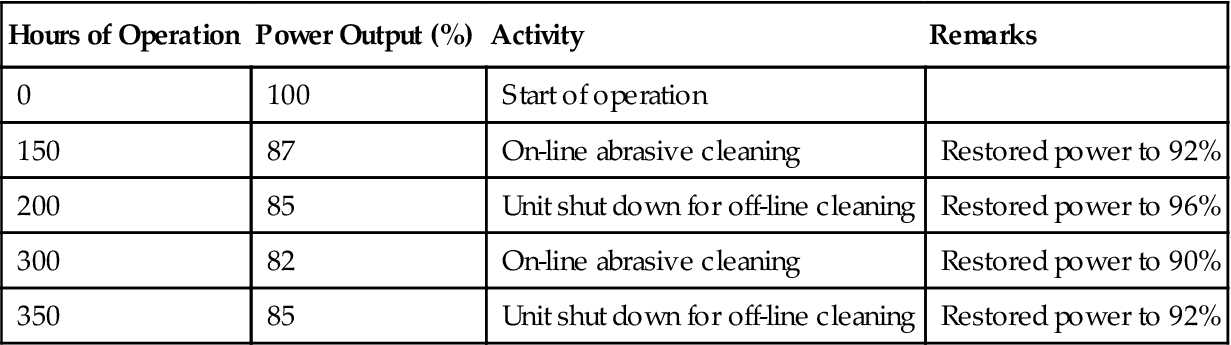
Inspection Intervals
Inspection intervals are specific to each installation, determined by the condition of the hot-gas-path parts. In addition to contaminant corrosion, fuel containing heavier hydrocarbons has a higher H2 content, which releases a higher amount of thermal energy during combustion. Higher combustion temperature leads to poorer hardware condition and shorter intervals between inspections. The number of equivalent operating hours (EOH), on which maintenance intervals are based, increases more rapidly based on fuel contaminant concentration. This can mean a factor of 1.5 for each operating hour.
A typical expected maintenance schedule follows in Table 7–10.
TABLE 7–10
Typical Maintenance Schedule [7-5]
| Inspection | Hours | Starts |
| Combustion system Hot gas path Major |
3000 6000–12,000 18,000–24,000 |
400 1200 2400 |
According to GE, several older gas turbines (7EA, Frame 5, and Frame 6) have accumulated several millions of hours of operation using “light Arabian crude” with V concentration of 10 to 30 ppm. The fuel is supplied directly from the refinery and then washed on site. An Mg additive is added at a ratio of 3:1 Mg:V. The units start and stop on crude. GE reports that after 1 million hours of operation, no significant hot path damage was found. Note that the older machines operate at much lower firing temperature (949°C or 1740°F) than modern gas turbines with a firing temperature of 1343°C or 2450°F or higher.
Success with Nonconventional Fuels10
Siemens’ experience in this arena demonstrates additional success with nonconventional fuel. Table 7–11 provides a sample of naphtha- and heavy oil-fired power plants in operation and in the planning stage. As this figure shows, some plants (e.g., Kot Addu and Valladolid) accumulated 30–60,000 hrs of successful operation over five years or more.
TABLE 7–11
Operational Experience with Naphtha and Heavy-oil-fired CC Plants [7-1]
| “Naphtha Class” projects∗: | |||||
| Plant Name | Location | Fuel | Gas Turbine Model | Rating | Operating Hours |
| Paguthan | India | Naphtha, Distillate, NG | 3 × V94.2 1 GUD 3.94.2 | 630 MW | 19,000 hours |
| Santa Rita | Philippines | Naphtha, Condensate, Distillate, NG | 4 × V84.3A 4 GUD 1S.84.3A | 950 MW | Erection phase |
| Faridabad | India | NG, Naphtha, HSD | 2 × V94.2 1 GUD 2.94.2 | 440 MW | Engineering phase |
| Latest plants with ash-forming fuels∗∗: | |||||
| Plant Name | Location | Fuel | Gas Turbine Model | Rating | Operating Hours |
| Valladolid | Mexico | Residual oil | 2 × V84.2 1 GUD 2.84.2 | 220 MW | 24,000 hrs |
| Kot Addu | Pakistan | Furnace oil (Heavy oil) | 4 × V94.2 2 GUD 2.94.2 | 820 MW | 60,000 hrs |
| Rousch | Pakistan | Heavy oil | 2 × V94.2 1 GUD 2.94.2 | 390 MW | Commissioning phase |
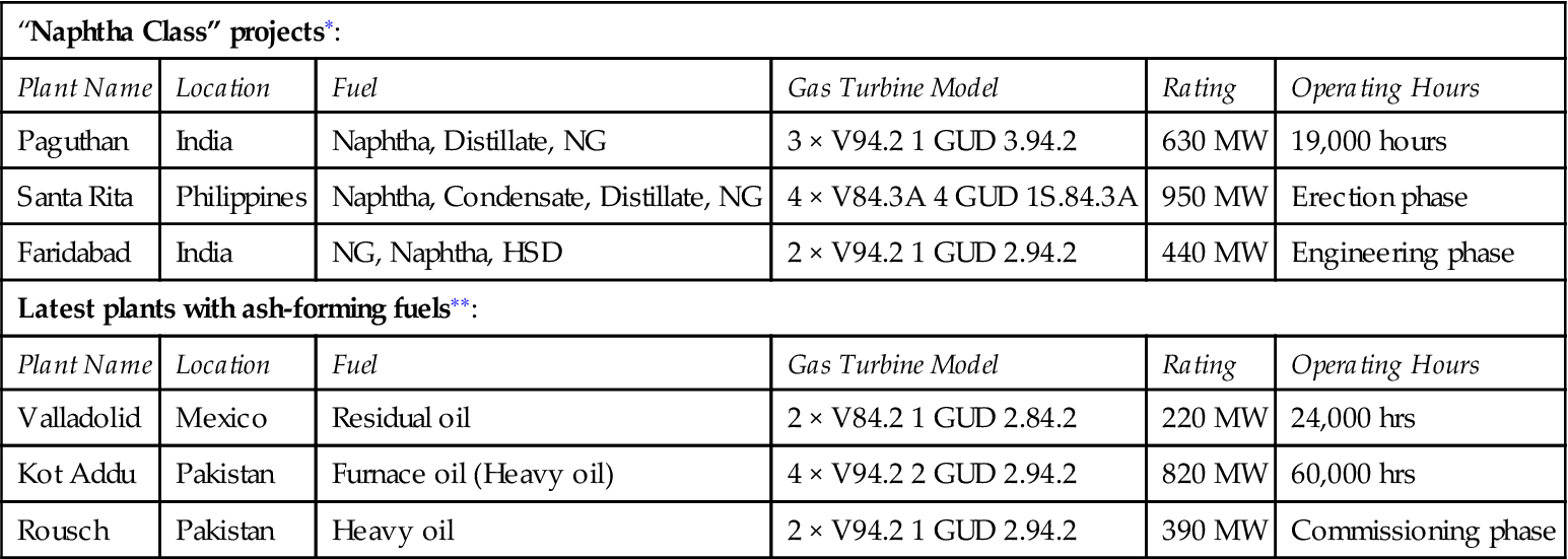
∗Note: 9 Gas Turbines ordered for fuels of “Naphtha Class”. “Naphtha Class” means light, low boiling liquid fuels.
∗∗Note: 34 Gas Turbines delivered for ash-formlng fuels In total accumulated operating hours approx. 140,000 hours.
As a result of the impacts of deregulation, environmental standards as well as usage as secondary fuels, up to 25% of the gas turbine output (in MWs) in the next 10 years could involve non-natural gas fuels. Naphtha is expected to be the dominant fuel in this category with a few thousand MW of new capacity being added every year.
Technology, Performance, and Design Trends
Design and operation of these plants requires more attention than natural-gas-fired plants particularly in relation to fuel variables such as calorific content, density, composition, concentration of contaminants, and emissions, as well as different burning behaviors (e.g., ignitability, flame velocity and stability).
To overcome these difficult fuel properties, technological adaptation, additional equipment, and operational requirements are necessary. These include GT-layout (compressor, turbine) for the changed mass flows, different burner technology (burner design, burner nozzles), additional startup/shutdown fuel system, and safety measures. Performance, availability and operation and maintenance (O&M) expenses can be affected. To illustrate this, Table 7–12 shows important nonstandard fuels and their effect on a standard fuel system.
TABLE 7–12
Gas Turbines for Nonstandard Fuels, Critical Fuel Properties [7-2]
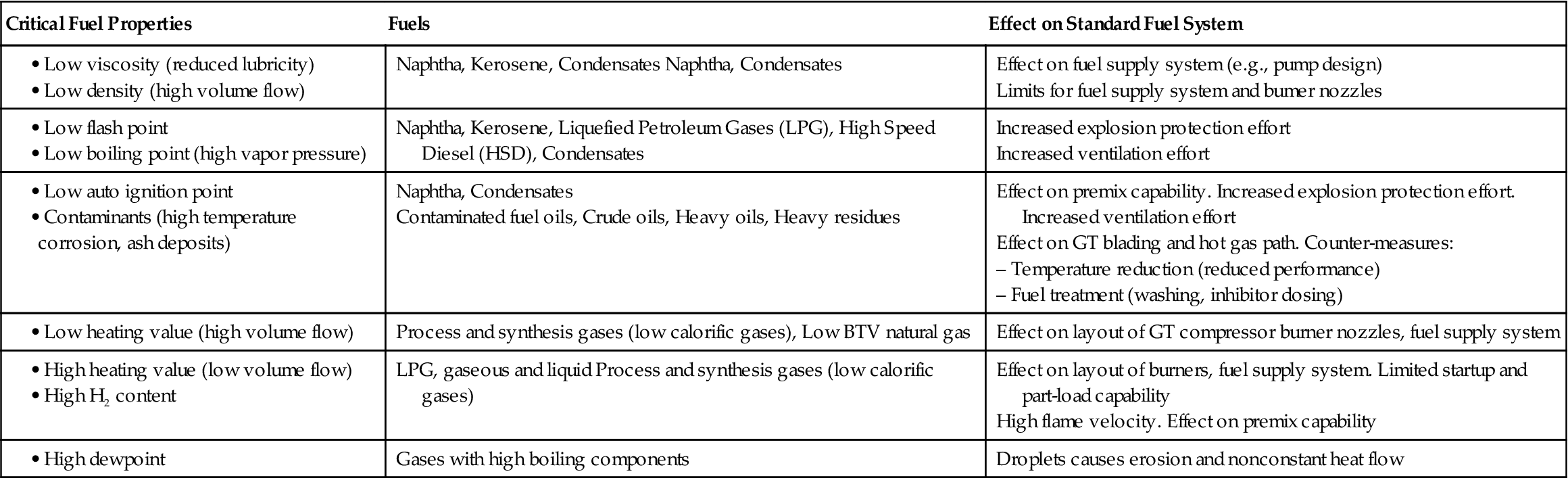
A Siemens example of gas turbine combined cycle plant burning a nonconventional fuel is the 220 MW Valladolid plant in Mexico. This plant has been operating since 1994, burning heavily contaminated fuel oil, containing 4.2% sodium and up to 300 ppm vanadium. Associated with this fuel are its impurities (sodium, potassium, and vanadium), which tend to form ash particles in the combustion process, form deposits, and corrode the gas turbine blades. In the case of the Valladolid plant, “Epsom salts,” consisting mainly of magnesium sulfate (MgSO4 7H2O), was dissolved in water injected into the gas turbine combustor through special orifices. This converts the vanadium into a stable water-soluble product (magnesium vanadates). While this is deposited downstream of the combustor on the gas turbine blades, it causes only minor blade corrosion and has to be removed through blade washing. At Valladolid, it was determined that washing every 150 hours was necessary to keep the aerodynamic performance of the blades, the plant efficiency, and reliability near to design levels. Good manhole access was a critical success factor for this project as servicing and maintenance during turbine washing shutdowns are simplified. It is planned to convert the Valladolid plant to natural gas operation in the near future.
OEM Design Requirements as They Relate to Integrated Gasification Combined-Cycle Plants
IGCC plants consist of three main sections: the “gas island” for conversion of coal and refinery residues (such as heavy fuel oil, vacuum residues, or petroleum coke) including gasification and downstream gas purification (removal of sulfur and heavy metal compounds in accord with required emissions levels), the air separation unit, and the combined-cycle plant. The modular design (gas generation, gas turbine system, HRSG, and the steam turbine system) offers the possibility of phased construction as well as retrofitting of CC plants with a gasification plant, thus replacing the “standard” gas turbine fuels (natural gas or fuel oil) by syngas produced from coal or refinery residues.
In principle, IGCC is a combination of two mature technologies; however, proper integration is the key to the success of the IGCC projects from lessons learned from several demonstration projects in Europe and the United States. Although more than 350 gasifiers are operating commercially worldwide and at least seven technology suppliers, and orders of more than 100 CC units per year are being handled by the major manufacturers, there is only limited experience of commercial operation as an integrated IGCC plant. IGCC can be expected to be a field of commercial application in developed countries, such as Italy, for residual refinery fuels and gasified coal.
Through 2015, the potential for refinery-based integrated coal gasification combined-cycle plants is estimated to be 135 GW. Currently over 6 GW of coal- and refinery-residue-based IGCC projects are either under construction or planned. Figure 7–27 shows some of the IGCC plants planned or under construction.
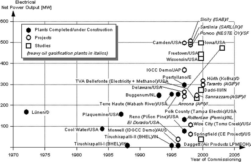
Technology, Performance, Environment, and Demand Trends
Figure 7–28 compares the supply flows, emissions, and by-products of different 600 MW-class plants. With reference to environmental emissions (including GHG), it may be seen that IGCC plants compare favorably with pulverized-coal-fired steam power plants.
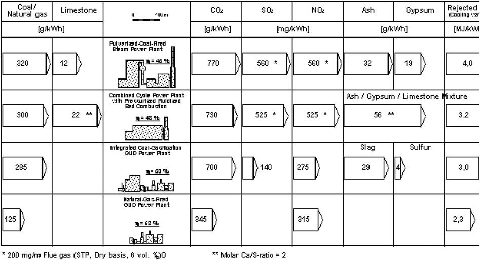
Depending on the degree of integration between the gas turbine and the air separation unit (ASU), either standard gas turbine/compressor configurations can be applied, or limited modifications are required, to compensate for the mismatch between turbine and compressor mass flows, which results from the application of gases with low heating values. Three principal options are available. The selection of the appropriate air and nitrogen integration concept depends on a number of factors to be considered on a case-by-case basis. A summary of the important criteria is provided in Figure 7–29.
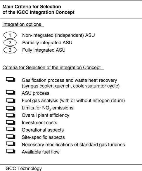
Figure 7–30 sets out the principal criteria for selection of the different IGCC integration concepts. The denominated “fully integrated approach,” which was selected for the European coal-based demonstration plants, resulted in the highest efficiency potential, but it is to be considered as highly sophisticated from the operational point of view. Nevertheless, after some initial operational problems, the Buggenum IGCC facility has demonstrated that this type of plant can be operated successfully and with the required availability.
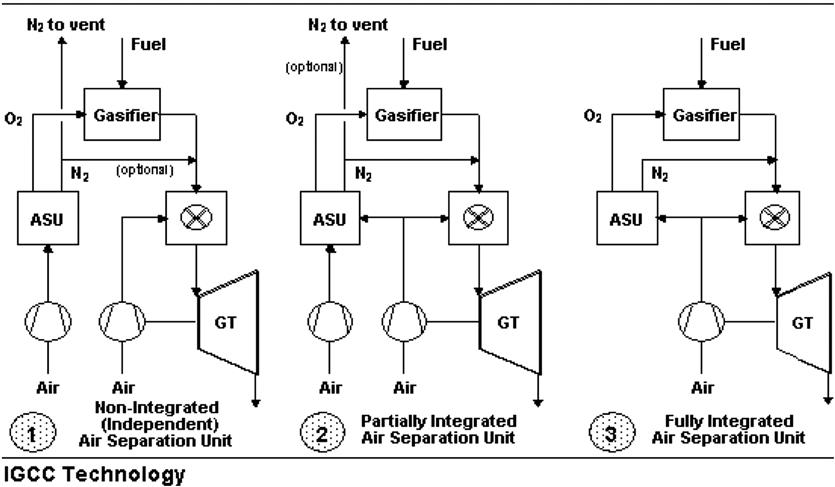
The nonintegrated concept with a completely independent ASU is expected to have advantages concerning simplification of plant operation and possibly in achievable availability. On the other hand, the loss in overall IGCC net plant efficiency compared with the fully integrated concept amounts to 1.5–2.5%. This concept therefore is primarily of interest for application in cases where efficiency is not the key factor (e.g., for the gasification of refinery residues).
The concept with partial air-side integration is an interesting compromise solution, with an only moderate loss in efficiency but improved plant flexibility compared with the fully integrated concept.
In summary, this OEM notes that
1. Industrial gas turbines, fired by natural gas, are a well-established technology. Ongoing development and the short-term introduction of the most advanced products improve GT efficiency to around 40%, with the largest GT capacities being in the range of 250–350 MW. This, in turn, improves the advanced CC efficiency to 60%, with corresponding plant capacities being in the range of 375–500 MW.
2. Using low cost salts, such as Epsom, as inhibitors, the GT components of CC plants can be successfully fired with refinery residues with high sodium and vanadium content. However, great care is needed in handling such difficult fuels.
3. IGCC can be expected to become a field of commercial application for residual refinery fuels (particularly in developed countries such as Italy) and gasified coal. However, great care needs to be taken in implementing an IGCC commercialization strategy for developing countries. Particular attention needs to paid to addressing integration issues.
Fuel Treatment Hardware11
Fuel Properties that Affect Fuel Treatment
Liquid Fuel
Liquid petroleum fuels fall into two basic classifications: true distillate and ash-forming oils. True distillate oils are most frequently the lighter oils such as naphtha, kerosene, and Number 2 distillate oil. This class of fuels is clean burning and behaves in a manner similar to natural gas as far as the internal portion of a gas turbine is concerned.
Naphtha, NGL, kerosene, and Light Number 1 distillate oil have little or no lubricity. Special handling equipment will be required in order to prevent damage to the peripheral equipment such as the main fuel pump, fuel nozzle plunger, flow dividers, etc.
Ash-forming oils are normally the heavier oils, such as blends, crude, and residual oils. Since they usually contain trace metal contaminants, fuel treatment is required to remove or modify the effects of harmful constituents prior to combustion in the power plant.
The degree of equipment sophistication, plant equipment investment and operating cost required for this treatment are tied directly to key physical and chemical properties of the fuel. Physically, the parameters of interest include specific gravity, viscosity, flash point, pour point, and wax content. Chemically, the prime interests are the amounts of corrosive trace metals present, the overall fuel washability, and compatibility of one fuel with another. The latter is particularly significant for users who obtain fuel from multiple sources (Figure 7–31).
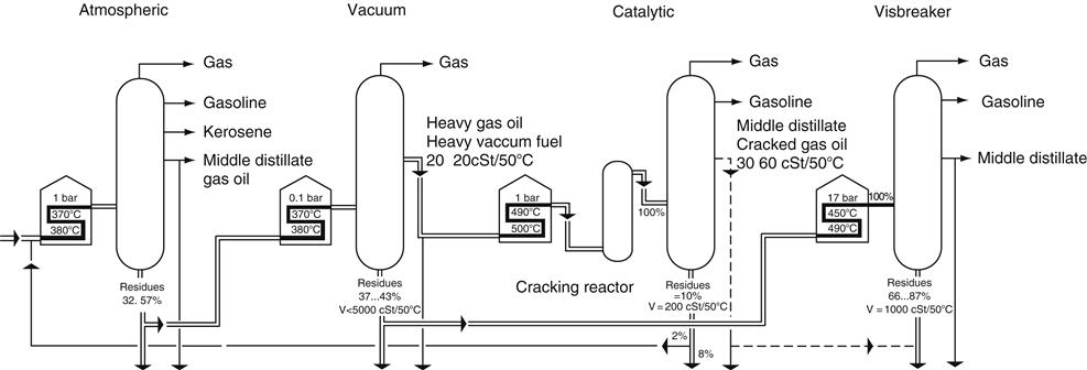
Trace Metals
Trace metal contaminants of concern include sodium, potassium, calcium, lead, vanadium, and magnesium. Vanadium, sodium, potassium, and lead are corrosive to turbine components (buckets and nozzles) at elevated temperatures, particularly when present in amounts above specification limits. All of these materials plus calcium can also form hard deposits that are difficult to remove. These deposits can cause plugging of the turbine nozzle, form deposits on the compressor blades, and reduce turbine output.
Table 7–13 lists the trace metals of interest, their effect on the turbines, and the means of treatment to reduce harmful effects along with typical permissible limits. Dealing with these metal contaminants will be discussed in the fuel treatment section of this book.
TABLE 7–13
| Trace Metal | Effects on Turbine | Type of Treatment |
| Sodium (Na) | High temperature corrosion | Fuel washing |
| Potassium (K) | ||
| Calcium (Ca) | Fouling deposits | Fuel washing to a limited extent |
| Lead (Pb) | High temperature corrosion | None, limit spec. |
| Vanadium∗ (V) | High temperature corrosion | Inhibited by magnesium |
| Magnesium (Mg) | Inhibits vanadium, forms deposits | Used to inhibit vanadium |
∗Vanadium levels less than 0.5 ppm do not require inhibition. Maximum vanadium levels may be dictated by local codes regarding stack particulate emissions and the user’s acceptable costs to inhibit.
(Source: Westfalia.)
Density
The density of a fuel oil is the ratio of the weight of a given volume of the oil at 15°C to the weight of an equal volume of distilled water at the same temperature.
The closer the density of the fuel is to that of the water, the more difficult it is to treat the fuel. Westfalia’s experience has shown that fuel with a high density of 0.991 can easily be processed by centrifugal separation.
Viscosity
The viscosity of a fluid is a measure of its resistance to flow and is expressed in various units. The most common viscosity units are kinematic viscosity in Centistokes (cSt), Saybolt Universal Seconds (SSU), and Saybolt Furol Seconds (SSF).
Westfalia’s experience has shown that viscosities of 1000 cSt at 50°C can easily be processed. Greater viscosities can be handled but they are evaluated on an individual basis.
Flash Point
The flash point is the lowest temperature at which application of a flame causes the vapor above a sample to ignite. This value indicates the potential fire hazard associated with handling fuels. Consideration should be given to explosion proofing if the flash point of any fuel that is used in the system is below 60°C.
Pour Point
The pour point is the lowest temperature at which the oil will flow under standard test conditions.
High pour points are characteristic for paraffin-based oils and dictate the need for increased storage temperature, higher capacity suction heaters, heat tracing of lines, as well as certain equipment and recirculation circuits to establish and maintain the operating temperature.
Wax Content
Wax can be present in fuel oil, particularly crude oil and heavy distillates. The percentage of wax and its melting point must be determined and suitable heating and heat tracing must be provided in order to ensure that the wax in the fuel is dissolved at all times.
Stability of Fuels
Future fuels will be of considerably poorer quality in the years to come. The major factor of such oils may be their incompatibility when oils from different refineries are used.
Incompatibility
At power plant installations, sludge of an asphaltic nature may be produced if fuels from different refineries are mixed. When this occurs, the fuels are incompatible. Such incompatibility first becomes evident in the form of excessive amounts of sludge separating out from the fuel. Asphalt sludge may also clog the pipes, heaters, and filters and collect in the tank’s bottom. Changing oil temperature has virtually no effect on the formation of sludge. The reason is that the more intensive refining process, particularly the use of the viscosity breakers (visbreakers), produces a higher content of asphaltenes. If a heavy oil of the above kind is mixed with a fuel that has a lower capacity for dissolving asphaltenes, the asphaltenes precipitate out of the fuel. Instability of this nature exists even when the mixed component is of a paraffin-base distillate.
Stability
Fuel oils are composed of many hydrocarbons of which four types are present in the largest volume. These are, in order of increasing instability: paraffin, naphthene, aromatics, and olefin being the most unstable. The stability of these hydrocarbons is governed by their resistance to oxidation or the ability to pick up oxygen and their reaction to heat and/or high temperature.
Sometimes an oil’s instability may go undetected. The following items are indicative of instability of fuel oils:
1. Excessive amount of sludge in storage tanks. There will be a normal amount found in most tanks but it should not accumulate rapidly.
2. Large carbon formation in preheaters, due to coking of some excessively heavy carbonaceous materials.
3. Large formation of soot caused by the incomplete combustion of the heavy precipitated insoluble compounds.
4. Thick sludge, waxy and gum-like substances found on screens and strainers.
Classical Heavy Fuel Oil (HFO)
The classical HFO is a mixture of residues from atmospheric and/or vacuum distillation processes and light distillate.
Atmospheric Distillation Desalted and dehydrated crude oil is heated in the distillation tower to 370–380°C and is split up into compounds of differing molecular structure (fractions) in a distillate tower at atmospheric pressure. The temperature is relatively low, otherwise the mineral oil products would begin to crack (decompose).
Fractions with a high hydrogen content are drawn off from the crude oil. The remaining residue contains molecules with a fairly low hydrogen and a fairly high carbon content. The combustion characteristics of this residue are fairly good.
Depending upon the source of the crude oil, the amounts of residue collected are between 32% and 57% relative to the initial quantity of crude oil.
Crude oils from the Middle East are generally of the paraffin base. The residual from this crude burns well.
Vacuum Distillation Vacuum distillation is a follow-up distillation process to the atmospheric distillation. Residual oil from the atmospheric distillation process can be fractionated to a further degree in a vacuum distillation process. The distillation takes place under a vacuum at a pressure of 100 mm of mercury. By means of this process, the residual from the atmospheric distillation can be reduced to 37–43% with a viscosity of 6000 cSt at 50°C. At the same time, a vacuum heavy oil with an approximate viscosity of 20–200 cSt at 50°C is obtained.
The residual fuel from vacuum distillation is extremely viscous (2000–6000 cSt at 50°C) and cannot be further broken down by distillation. It can be processed into bitumen for road building.
At the present time, the vacuum residue is still being blended with inexpensive distillate to bring it to the viscosity of heavy fuel oil. However, it is increasingly becoming the practice to reduce its viscosity in the viscosity breaker (visbreaker) in order to save on distillate fuel.
Another possibility for further processing is to coke the vacuum residue into petroleum coke by splitting off light components.
The other refining method is called cracking. This method is divided into two distinct types: catalytic cracking and thermal cracking (viscosity breaking—visbreaking). The catalytic cracking method is the more modern and efficient method.
Low-Grade Heavy Fuel Oil (HFO)
The low grade HFO will contain residues from the catalytic cracker and visbreaker in addition to the classical HFO.
Catalytic Cracker The cracking processes involved in these cases are used to obtain distillates with a desired boiling point from vacuum heavy oil by molecular cleavage. In this distillation process the existing molecules are segregated into fractions. Large high-viscosity molecules are converted into small fluid low-viscosity hydrocarbon molecules. Light distillates are thus obtained but these distillates have a hydrogen deficiency.
There are many catalytic cracking processes. Heavy vacuum distillate is cracked to a further degree by the use of a powdered aluminum silicate catalyst. This catalyst is heated to approximately 700°C and mixed with the vacuum heavy oil, then preheated to approximately 420°C, before being fed into the reaction chamber. In the reaction chamber, the catalyst causes the molecules of the vacuum heavy oil to split at a process temperature of approximately 500°C and a pressure of 1 bar.
Cracked residual is particularly low in hydrogen and rich in carbon and it contains a large proportion of unsaturated hydrocarbons. This means increased sludge formation and accompanied in some cases by abrasive residues in powder form from the catalyst. The quantities of this catalyst may be as high as 200–300 ppm. Therefore, the fuel must be cleaned (remover of the catalytic fines) before it is used in diesel engines and gas turbines.
From the heavy vacuum fuel about 90% will be converted to middle distillate in a catalytic cracker. This distillate fuel will have a viscosity of 30–50 cSt at 50°C, of which 10% will be residue with a viscosity of 200 cSt at 50°C. From this, 2% will be routed back to the atmospheric distillation tower.
Viscosity Breaking (Visbreaking—Thermal Cracking)
Visbreaking is a simple process in which the very viscous residues from the vacuum distillation or even the atmospheric residues are subjected to thermal treatment at 450–490°C and 17 bars pressure. This results in the formation of low molecular weight, low-viscosity hydrocarbons that considerably reduce the residual viscosity.
Because the obtained residual is occasionally too viscous, it is diluted with cracked gas oil. Cracked gas oil is used as a diluent in order to reduce the tendency to sediment formation (the separating out of asphaltenes). Because of the high asphaltene content, the question of compatibility with other heavy fuel oils is particularly important (formation of excessive sludge in the centrifuge).
From the 100% stock at 450–490°C and 17 bars that enters the visbreaker, 66–87% of it is a residual fuel with a viscosity of up to 1000 cSt at 50°C.
Note: Based on the new distillation processes where sludge and catalytic fines are produced, no electrostatic desalter is recommended as a fuel treatment system for gas turbine fuels.
Fuel Treatment
Liquid Fuel Treatment
In the case of a true light distillate oil, treatment is required primarily to capture dirt and shipment contaminants that have not been removed by settling in the fuel storage tanks. Undetected and untreated, a single shipment of contaminated fuel can cause substantial damage to a power plant. Filters are the most commonly used device although centrifuges and sometimes other desalting methods may also be required to remove sodium if present as a result of seawater contamination.
Treatment and conditioning systems for ash-forming fuels are more complex because of the processing steps required to remove or control their characteristic trace metal contaminants. Particular attention must be paid to sodium, potassium, lead, and vanadium. Complete fuel treatment includes:
1. Washing the fuel to remove the water-soluble trace metals such as sodium, potassium, and certain calcium compounds. Centrifugal washing also removes much of the inorganic particulate material that is normally forwarded to the filtering system. Washing involves the addition of water to the fuel and subsequent removal of the contaminant laden water. Under special circumstances it may be possible to remove the water that is in the raw fuel without adding water and still be able to obtain adequate contaminant removal. This special process is called “fuel purification” and is frequently applied to light crude oils and distillate. Fuel purification is discussed in a separate technical paper.
2. Filtering the fuel to remove solids, oxides, silicates, and other related compounds that are not adequately removed prior to forwarding of the fuel to power plants. These particles can clog fuel pumps, fuel nozzle plungers, flow dividers, and fuel nozzles.
3. Inhibiting the vanadium in the fuel with magnesium compounds in a ratio of three parts of magnesium, by weight, to each part of vanadium. This form of treatment inhibits the corrosive characteristics of vanadium by forming high-melting temperature ash composed of magnesium sulfate, magnesium oxide, and magnesium vanadates.
Lead is also corrosive to power plant components (turbines) and should be avoided. Since there is no economical technique for removing or providing an inhibitor, it is necessary to only purchase fuel with extremely low amounts of lead (less than 1 ppm).
Fuel Washing
Since heavy fuel oils are almost universally contaminated with salts and salt water, they normally require water washing to remove the water-soluble salts of sodium and potassium. Fuel washing involves mixing heated fuel with 5–10% of potable water along with a small amount (0.02%) of an emulsion-breaking fluid to aid in separation. The washing process is a two-stage extraction procedure with the extraction water flowing counter-current to the fuel. Each stage has a mixer to initiate contact of the washwater with the fuel, followed by a mechanism to separate the salt-laden water from the extracted fuel.
The number of extraction stages required depends on the salt level in the fuel to be processed and on certain properties of the fuel such as specific gravity and viscosity. Since the successful operation of the fuel-washing system depends on a working difference between the specific gravities of fuel and that of water, fuels with specific gravities above 0.991 may not be washable unless they are first blended with a compatible liquid that has a lower specific gravity such as distillate fuel.
Chemicals referred to as demulsifiers are added to the fuel to assist in breaking up difficult oil/water emulsions.
Water is added to the fuel oil and is subjected to controlled mixing in order to distribute the sodium-seeking water throughout the raw fuel. The mixture of water and oil flows to a separator that is a mechanical centrifuge. In the centrifuge, the oil and water are separated under centrifugal force, the cleaned oil flows into one circuit and the latent wash water with a high concentration of salts flows out from the centrifuge through another circuit.
The effluent water may require a treatment system to remove the entrained oil to comply with local codes.
For example, a customer specification of “no visible sheen” which is approximately 15 ppm of free oil in the water. Reduction of oil content below these values may require a complicated system.