Day 30. PVST and Rapid PVST+ Operation and Configuration
CCNA 200-101 ICND2 Exam Topics
![]() Identify enhanced switching technologies
Identify enhanced switching technologies
![]() Configure and verify PVSTP operation
Configure and verify PVSTP operation
Key Topics
The original Spanning Tree Protocol (STP) IEEE 802.1D standard only allowed for one instance of STP to run for the entire switched network. Today’s review specifically covers Per-VLAN Spanning Tree (PVST) and Rapid STP (RSTP), both of which improved the original standard.
PVST Operation
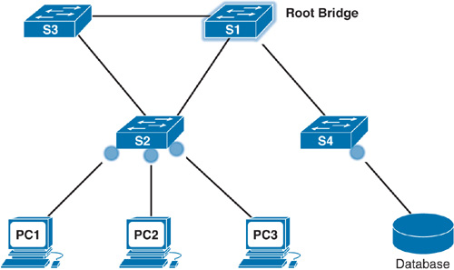
PVST Plus (PVST+) is the default setting on all Cisco Catalyst switches. In a PVST+ environment, you can tune the spanning-tree parameters so that half the VLANs forward on each uplink trunk. You do this by configuring one switch to be elected the root bridge for half of the VLANs in the network and a second switch to be elected the root bridge for the other half of the VLANs. In the example shown in Figure 30-1, S1 is the root bridge for VLAN 10, and S3 is the root bridge for VLAN 20.

From the perspective of S2, a port will be forwarding or blocking depending on the VLAN instance. After convergence, port F0/2 will be forwarding VLAN 10 frames and blocking VLAN 20 frames. Port F0/3 will be forwarding VLAN 20 frames and blocking VLAN 10 frames.
Switched networks running PVST+ have the following characteristics:
![]() Configured PVST per VLAN allows redundant links to be fully utilized.
Configured PVST per VLAN allows redundant links to be fully utilized.
![]() Each additional spanning-tree instance for a VLAN adds more CPU cycles to all switches in the network.
Each additional spanning-tree instance for a VLAN adds more CPU cycles to all switches in the network.
Port States
The spanning tree is determined immediately after a switch is finished booting. If a switch port transitions directly from the blocking to the forwarding state without information about the full topology during the transition, the port can temporarily create a data loop. For this reason, STP introduces the five port states. Table 30-1 describes the port states that ensure that no loops are created during the creation of the logical spanning tree.

Extended System ID
PVST+ requires a separate instance of spanning tree for each VLAN. The BID field in the BPDU must carry VLAN ID (VID) information, as shown in Figure 30-2.

The BID includes the following fields:
![]() Bridge Priority: A 4-bit field is still used to carry bridge priority. However, the priority is conveyed in discrete values in increments of 4096 rather than discrete values in increments of 1 because only the first 4 most-significant bits are available from the 16-bit field.
Bridge Priority: A 4-bit field is still used to carry bridge priority. However, the priority is conveyed in discrete values in increments of 4096 rather than discrete values in increments of 1 because only the first 4 most-significant bits are available from the 16-bit field.
![]() Extended System ID: A 12-bit field carrying the VID for PVST+.
Extended System ID: A 12-bit field carrying the VID for PVST+.
![]() MAC Address: A 6-byte field with the MAC address of a single switch.
MAC Address: A 6-byte field with the MAC address of a single switch.
Rapid PVST+ Operation
In Rapid PVST+, a single instance of RSTP runs for each VLAN. This is why Rapid PVST+ has a very high demand for switch resources (CPU cycles and RAM).
Note
Rapid PVST+ is simply the Cisco implementation of RSTP on a per-VLAN basis. The rest of this review uses RSTP and Rapid PVST+ interchangeably.
With RSTP, IEEE improved the convergence performance of STP from 50 seconds to less than 10 seconds with its definition of Rapid STP (RSTP) in the standard 802.1w. RSTP is identical to STP in the following ways:
![]() It elects the root switch using the same parameters and tiebreakers.
It elects the root switch using the same parameters and tiebreakers.
![]() It elects the root port on nonroot switches with the same rules.
It elects the root port on nonroot switches with the same rules.
![]() It elects designated ports on each LAN segment with the same rules.
It elects designated ports on each LAN segment with the same rules.
![]() It places each port in either forwarding or discarding state, although RSTP calls the blocking state the discarding state.
It places each port in either forwarding or discarding state, although RSTP calls the blocking state the discarding state.
RSTP Interface Behavior
The main changes with RSTP can be seen when changes occur in the network. RSTP acts differently on some interfaces based on what is connected to the interface:
![]() Edge-type behavior and PortFast: RSTP improves convergence for edge-type connections by immediately placing the port in forwarding state when the link is physically active.
Edge-type behavior and PortFast: RSTP improves convergence for edge-type connections by immediately placing the port in forwarding state when the link is physically active.
![]() Link-type shared: RSTP does not do anything differently from STP on link-type shared links. However, because most links between switches today are full duplex, point-to-point, and not shared, it does not matter.
Link-type shared: RSTP does not do anything differently from STP on link-type shared links. However, because most links between switches today are full duplex, point-to-point, and not shared, it does not matter.
![]() Link-type point-to-point: RSTP improves convergence over full-duplex links between switches. RSTP recognizes the loss of the path to the root bridge, through the root port, in 6 seconds based on 3 times the Hello timer value of 2 seconds. So, RSTP recognizes a lost path to the root much more quickly.
Link-type point-to-point: RSTP improves convergence over full-duplex links between switches. RSTP recognizes the loss of the path to the root bridge, through the root port, in 6 seconds based on 3 times the Hello timer value of 2 seconds. So, RSTP recognizes a lost path to the root much more quickly.
RSTP uses different terminology to describe port states. Table 30-2 lists the port states for RSTP and STP.

RSTP removes the need for listening state and reduces the time required for learning state by actively discovering the network’s new state. STP passively waits on new BPDUs and reacts to them during the listening and learning states. With RSTP, the switches negotiate with neighboring switches by sending RSTP messages. The messages enable the switches to quickly determine whether an interface can be immediately transitioned to a forwarding state. In many cases, the process takes only a second or two for the entire RSTP domain.
RSTP Port Roles
RSTP also adds three more port roles in addition to the root port and designated port roles defined in STP. Table 30-3 lists and defines the port roles.

Figure 30-3 shows an example of these RSTP port roles.

Edge Ports
In addition to these port roles, RSTP uses an edge port concept that corresponds to the PVST+ PortFast feature. An edge port connects directly to an end device. Therefore, the switch assumes that no other switch is connected to it. RSTP edge ports should immediately transition to the forwarding state, thereby skipping the time-consuming original 802.1D listening and learning port states. The only caveat is that the port must be a point-to-point link. If it is a shared link, then the port is nonedge and PortFast should not be configured. Why? Another switch could be added to a shared link, on purpose or inadvertently. Figure 30-4 shows examples of edge ports.
Configuring and Verifying Varieties of STP
By default, all Cisco switches use STP without any configuration by the network administrator. However, because STP runs on a per-VLAN basis, you can take advantage of several options to load balance traffic across redundant links.
STP Configuration Overview
Before you configure or alter the behavior of STP, it is important to know the current default settings list in Table 30-4.

Configuring and Verifying the BID
Regardless of which PVST you use, two main configuration options can help you achieve load balancing: the bridge ID and port cost manipulation. The bridge ID influences the choice of root switch and can be configured per VLAN. Each interface’s (per-VLAN) STP cost to reach the root influences the choice of designated port on each LAN segment. Because PVST requires that a separate instance of spanning tree run for each VLAN, the BID field is required to carry VLAN ID (VID) information. This is accomplished by reusing a portion of the Priority field as the extended system ID to carry a VID.
To change the bridge ID, use one of the following commands:
Switch(config)# spanning-tree vlan vlan-id root {primary | secondary}
Switch(config)# spanning-tree vlan vlan-id priority priority
To change the interface cost, use the following command:
Switch(config-if)# spanning-tree vlan vlan-id cost cost
Figure 30-5 shows a simple three-switch STP topology without redundant links.

The network administrator wants to ensure that S1 is always the root bridge and S2 is the backup root bridge. The following commands achieve this objective:
S1(config)# spanning-tree vlan 1 root primary
!---------
S2(config)# spanning-tree vlan 1 root secondary
The primary keyword automatically sets the priority to 24576 or to the next 4096 increment value below the lowest bridge priority detected on the network.
The secondary keyword automatically sets the priority to 28672, assuming the rest of the network is set to the default priority of 32768.
Alternatively, the network administrator can explicitly configure the priority value in increments of 4096 between 0 and 65536 using the following command:
S1(config)# spanning-tree vlan 1 priority 24576
!---------
S2(config)# spanning-tree vlan 1 priority 28672
Note
These commands changed the priority values only for VLAN 1. Additional commands must be entered for each VLAN to take advantage of load balancing.
To verify the current spanning-tree instances and root bridges, use the show spanning-tree command, as shown in Example 30-1.
Example 30-1 Verifying Spanning-Tree Configurations
S1# show spanning-tree
VLAN0001
Spanning tree enabled protocol ieee
Root ID Priority 24577
Address 001b.5302.4e80
This bridge is the root
Hello Time 2 sec Max Age 20 sec Forward Delay 15 sec
Bridge ID Priority 24577 (priority 24576 sys-id-ext 1)
Address 001b.5302.4e80
Hello Time 2 sec Max Age 20 sec Forward Delay 15 sec
Aging Time 300
Interface Role Sts Cost Prio.Nbr Type
---------------- ---- --- --------- -------- --------------------------------
Fa0/1 Desg FWD 19 128.1 P2p
Fa0/2 Desg FWD 19 128.2 P2p
Because an extended system ID is used in the BID, the value of the priority includes the addition of the VLAN ID. So, a priority of 24576 plus a VLAN of 1 results in a priority output of 24577.
Configuring PortFast
To speed up convergence for access ports when they become active, you can use Cisco’s proprietary PortFast technology. After PortFast is configured and a port is activated, the port immediately transitions from the blocking state to the forwarding state. Example 30-2 shows the interface command to configure PortFast (assuming that S2 in Figure 30-5 is attached to an end device on F0/11).
Example 30-2 Configuring PortFast
S2# configure terminal
Enter configuration commands, one per line. End with CNTL/Z.
S2(config)# interface f0/11
S2(config)# switchport mode access
S2(config-if)# spanning-tree portfast
Alternatively, you can configure the global command spanning-tree portfast default, which enables PortFast by default on all access ports.
Configuring Rapid PVST+
Remember, PVST+ is the default operation of Cisco switches. To change to rapid PVST+, use a single global command on all switches: spanning-tree mode rapid-pvst.
Table 30-5 summarizes all the rapid PVST+ related commands.

Verifying STP
A number of commands enable you to verify the state of the current STP implementation. Table 30-6 summarizes commands most likely to appear on the CCNA exam.

Note
Ideally, you should review the output of these commands today on lab equipment or a simulator. At the very least, refer to the examples in your study resources.