Day 24. OSPFv2 Modification
CCNA 200-101 ICND2 Exam Topics
![]() Configure and verify OSPF (single-area)
Configure and verify OSPF (single-area)
Key Topics
Both the CCENT and the CCNA exams test the skills and knowledge associated with the Open Shortest Path First (OSPF) Protocol. The CCENT exam focuses on OSPF concepts and configuring and verifying single-area OSPFv2 and OSPFv3. Then the CCNA exam extends OSPFv2 and OSPFv3 coverage to include modifying OSPF configurations, configuring multi-area OSPF, and troubleshooting. Today’s review focuses on OSPFv2.
Configuring OSPFv2 Review
This first section is a necessary review of basic OSPFv2 configuration. If you are already comfortable with these tasks, feel free to skip this section.
The router ospf Command
You enable OSPF with the router ospf process-id global configuration command:
Router(config)# router ospf process-id
The process-id is a number between 1 and 65,535 and is chosen by the network administrator. The process ID is locally significant. It does not have to match other OSPF routers to establish adjacencies with those neighbors.
The network Command
The network command is used in router configuration mode:
Router(config-router)# network network-address wildcard-mask area area-id
The OSPF network command uses a combination of network-address and wildcard-mask. The network address, along with the wildcard mask, is used to specify the interface or range of interfaces that will be enabled for OSPF using the network command.
The area area-id refers to the OSPF area. An OSPF area is a group of routers that share link-state information. All OSPF routers in the same area must have the same link-state information in their link-state databases. Therefore, all the routers within the same OSPF area must be configured with the same area ID on all routers. By convention, the area ID is 0.
Router ID
The router ID plays an important role in OSPF. It is used to uniquely identify each router in the OSPF routing domain. Cisco routers derive the router ID based on three criteria in the following order:
1. Use the IP address configured with the OSPF router-id command.
2. If the router ID is not configured, the router chooses the highest IP address of any of its loopback interfaces.
3. If no loopback interfaces are configured, the router chooses the highest active IP address of any of its physical interfaces.
Because the OSPF router-id command can be controlled by the network administrator and because loopback interfaces clutter up the routing table, it is a best practice to configure the router-id command. The router-id command is configured in router configuration mode and accepts an IPv4 address as its only argument:
Router(config-router)# router-id ip-address
Passive Interfaces
By default, OSPF messages are forwarded out all OSPF-enabled interfaces. However, these messages really only need to be sent out interfaces connecting to other OSPF-enabled routers. Use the passive-interface command in router configuration mode to prevent OSPF updates from being sent out unnecessary interfaces:
Router(config)# passive-interface interface
As an alternative, you can make all interfaces passive by using the passive-interface default command. Then you can re-enable interfaces that should not be passive by using the no passive-interface interface command.
Modifying the OSPF Metric
Cisco IOS Software uses the cumulative bandwidths of the outgoing interfaces from the router to the destination network as the cost value. At each router, the cost for an interface is calculated using the following formula:
Cisco IOS Cost for OSPF = 108 / Bandwidth in bps
In this calculation, the value 108 is known as the reference bandwidth. Table 24-1 shows the default OSPF costs using the default reference bandwidth for several types of interfaces.

In Table 24-1, 10GigE, Gigabit Ethernet, and Fast Ethernet all have the same cost. That’s because the OSPF cost value must be an integer. This was not an issue before the introduction of gigabit and higher data rates.
However, today’s networks are certainly running at gigabit speeds. Therefore, as a matter of policy, you should change the reference bandwidth to accommodate networks with links faster than 100,000,000 bps (100 Mbps). Use the following command to change the reference bandwidth:
Router(config-router)# auto-cost reference-bandwidth Mbps
Because the value entered is in Mbps, changing the reference bandwidth to 10000 will ensure that all OSPF routers are ready to accurately calculate cost for 10GigE networks. When used, this command should be entered on all routers so that the OSPF routing metric remains consistent.
But we are not done. There is still one more adjustment we need to make to ensure that OSPF is using accurate costs. On Cisco routers, the default bandwidth on most serial interfaces is set to T1 speed, or 1.544 Mbps. But the actual contracted speed may be different. In those cases, the cost metric needs to be explicitly configured. You can modify the OSPF metric in two ways:
![]() Use the bandwidth command to modify the bandwidth value used by the Cisco IOS Software in calculating the OSPF cost metric.
Use the bandwidth command to modify the bandwidth value used by the Cisco IOS Software in calculating the OSPF cost metric.
![]() Use the ip ospf cost command, which allows you to directly specify the cost of an interface.
Use the ip ospf cost command, which allows you to directly specify the cost of an interface.
An advantage of configuring a cost over setting the interface bandwidth is that the router does not have to calculate the metric when the cost is manually configured. Also, the ip ospf cost command is useful in multivendor environments, where non-Cisco routers can use a metric other than bandwidth to calculate the OSPF costs.
OSPFv2 Configuration Example
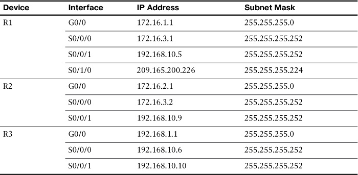
To review the OSPF configuration commands, we will use the topology in Figure 24-1 and the addressing scheme in Table 24-2.

Example 24-1 shows the network commands for all three routers, enabling OSPF on all interfaces.
Example 24-1 Configuring OSPF Networks
R1(config)# router ospf 10
R1(config-router)# router-id 1.1.1.1
R1(config-router)# network 172.16.1.0 0.0.0.255 area 0
R1(config-router)# network 172.16.3.0 0.0.0.3 area 0
R1(config-router)# network 192.168.10.4 0.0.0.3 area 0
R1(config-router)# passive-interface g0/0
R1(config-router)# passive-interface s0/1/0
R1(config-router)# auto-cost reference-bandwidth 10000
R1(config-router)# interface S0/0/1
R1(config-if)# bandwidth 64
R2(config)# router ospf 10
R2(config-router)# router-id 2.2.2.2
R2(config-router)# network 172.16.2.0 0.0.0.255 area 0
R2(config-router)# network 172.16.3.0 0.0.0.3 area 0
R2(config-router)# network 192.168.10.8 0.0.0.3 area 0
R2(config-router)# passive-interface g0/0
R2(config-router)# auto-cost reference-bandwidth 10000
R2(config-router)# interface S0/0/1
R2(config-if)# bandwidth 1024
R3(config)# router ospf 10
R3(config-router)# router-id 3.3.3.3
R3(config-router)# network 192.168.1.0 0.0.0.255 area 0
R3(config-router)# network 192.168.10.4 0.0.0.3 area 0
R3(config-router)# network 192.168.10.8 0.0.0.3 area 0
R3(config-router)# passive-interface g0/0
R3(config-router)# auto-cost reference-bandwidth 10000
R3(config-router)# interface S0/0/0
R3(config-if)# bandwidth 64
R3(config-if)# interface S0/0/1
R3(config-if)# bandwidth 1024
Modifying Single-Area OSPFv2
This section reviews the concepts and commands to redistribute a default route, tune OSPF interfaces, authenticate updates, and manipulate the designated router/backup designated router (DR/BDR) election process.
Redistributing a Default Route
In Figure 24-1, R1 has a link to the Internet that makes R1 an Autonomous System Boundary Router (ASBR). So, we configure a default route to the Internet and redistribute the default static route to R2 and R3 with the default-information originate command, as demonstrated in Example 24-2.
Example 24-2 ASBR Static Default Route Configuration
R1(config)# ip route 0.0.0.0 0.0.0.0 Serial 0/1/0
R1(config)# router ospf 10
R1(config-router)# default-information originate
Both R2 and R3 should now have default routes identified with the O*E2 code, as shown in Example 24-3.
Example 24-3 R2 and R3 OSPF Routes with Default Route
R2# show ip route ospf
172.16.0.0/16 is variably subnetted, 5 subnets, 3 masks
O 172.16.1.0 [110/6477] via 172.16.3.1, 00:02:45, Serial0/0/0
O 192.168.1.0 [110/6486] via 192.168.10.10, 00:00:55, Serial0/0/1
192.168.10.0/24 is variably subnetted, 3 subnets, 2 masks
O 192.168.10.4 [110/12952] via 192.168.10.10, 00:00:55, Serial0/0/1
O*E2 0.0.0.0/0 [110/1] via 172.16.3.1, 00:00:09, Serial0/0/0
R3# show ip route ospf
172.16.0.0/16 is variably subnetted, 3 subnets, 2 masks
O 172.16.1.0 [110/6477] via 192.168.10.5, 00:26:01, Serial0/0/0
O 172.16.2.0 [110/6486] via 192.168.10.9, 00:26:01, Serial0/0/1
O 172.16.3.0 [110/6540] via 192.168.10.5, 00:26:01, Serial0/0/0
O*E2 0.0.0.0/0 [110/1] via 192.168.10.9, 00:01:19, Serial0/0/1
Modifying Hello Intervals and Hold Times
It might be desirable to change the OSPF timers so that routers will detect network failures in less time. Doing this will increase traffic, but sometimes a need for quick convergence outweighs the extra traffic.
You can modify OSPF Hello and Dead intervals manually by using the following interface commands:
Router(config-if)# ip ospf hello-interval seconds
Router(config-if)# ip ospf dead-interval seconds
Example 24-4 shows the Hello and Dead intervals modified to 5 seconds and 20 seconds, respectively, on the serial 0/0/0 interface for R1.
Example 24-4 Modifying Hello and Dead Intervals on R1
R1(config)# interface serial 0/0/0
R1(config-if)# ip ospf hello-interval 5
R1(config-if)# ip ospf dead-interval 20
R1(config-if)# end
Remember, unlike Enhanced Interior Gateway Routing Protocol (EIGRP), OSPF Hello and Dead intervals must be equivalent between neighbors. So, R2 should be configured with the same intervals.
Authenticating OSPF Messages
By default, OSPF link-state advertisements (LSAs) from a neighbor are accepted and used by the local router to calculate the link states and choose the best routes. For this reason, it is a security best practice to configure routers to authenticate routing messages. There are three types of authentication in OSPF:
![]() Null: The default; no authentication is used.
Null: The default; no authentication is used.
![]() Simple password authentication: Legacy authentication method that uses a plain-text password.
Simple password authentication: Legacy authentication method that uses a plain-text password.
![]() MD5 authentication: Currently the most secure method for exchanging routing updates, because the password is never exchanged.
MD5 authentication: Currently the most secure method for exchanging routing updates, because the password is never exchanged.
MD5 (message digest algorithm 5) authentication can be enabled globally for all interfaces or on a per-interface basis. To enable OSPF MD5 authentication globally, configure the following:
![]() ip ospf message-digest-key key md5 password interface configuration mode command
ip ospf message-digest-key key md5 password interface configuration mode command
![]() area area-id authentication message-digest router configuration mode command
area area-id authentication message-digest router configuration mode command
This method forces authentication on all OSPF-enabled interfaces. If an interface is not configured with the ip ospf message-digest-key command, it cannot form adjacencies with other OSPF neighbors.
To provide more flexibility, authentication is now supported on a per-interface basis. To enable MD5 authentication on a per-interface basis, configure the following:
![]() ip ospf message-digest-key key md5 password interface configuration mode command
ip ospf message-digest-key key md5 password interface configuration mode command
![]() ip ospf authentication message-digest interface configuration mode command
ip ospf authentication message-digest interface configuration mode command
Global and per-interface OSPF MD5 authentication can be used on the same router; however, the interface setting overrides the global setting.
Example 24-5 shows how to configure R1 globally for OSPF MD5 authentication.
Example 24-5 Enabling OSPF MD5 Authentication Globally
R1(config)# router ospf 10
R1(config-router)# area 0 authentication message-digest
R1(config-router)# exit
%OSPF-5-ADJCHG: Process 10, Nbr 2.2.2.2 on Serial0/0/0 from FULL to DOWN, Neighbor Down: Dead timer expired
%OSPF-5-ADJCHG: Process 10, Nbr 3.3.3.3 on Serial0/0/1 from FULL to DOWN, Neighbor Down: Dead timer expired
R1(config-if)# interface Serial 0/0/0
R1(config-if)# ip ospf message-digest-key 1 md5 CISCO-123
R1(config-if)# interface Serial 0/0/1
R1(config-if)# ip ospf message-digest-key 1 md5 CISCO-123
R1(config-if)# end
R1#
Notice in the output that neighbor adjacency with R2 and R3 is lost because authentication fails. Example 24-6 shows how to configure R2 on a per-interface basis for MD5 authentication.
Example 24-6 Enabling OSPF MD5 Authentication on a Per-Interface Basis
R2(config)# interface Serial 0/0/0
R2(config-if)# ip ospf message-digest-key 1 md5 CISCO-123
R2(config-if)# ip ospf authentication message-digest
%OSPF-5-ADJCHG: Process 10, Nbr 1.1.1.1 on Serial0/0/0 from LOADING to FULL,
Loading Done
R2(config-if)# interface Serial 0/0/1
R2(config-if)# ip ospf message-digest-key 1 md5 CISCO-123
R2(config-if)# ip ospf authentication message-digest
%OSPF-5-ADJCHG: Process 10, Nbr 3.3.3.3 on Serial0/0/1 from FULL to DOWN, Neighbor
Down: Dead timer expired
%OSPF-5-ADJCHG: Process 10, Nbr 3.3.3.3 on Serial0/0/1 from FULL to DOWN, Neighbor
Down: Interface down or detached
R2(config-if)#
To finish the configuration of the topology in Figure 24-5, R3 should also be configured with OSPF MD5 authentication, as shown in Example 24-7.
Example 24-7 Enabling OSPF MD5 Authentication Globally on R3
R3(config)# router ospf 10
R3(config-router)# area 0 authentication message-digest
R3(config-router)# interface Serial 0/0/0
R3(config-if)# ip ospf message-digest-key 1 md5 CISCO-123
R3(config-if)# interface Serial 0/0/1
R3(config-if)# ip ospf message-digest-key 1 md5 CISCO-123
R3(config-if)#
%OSPF-5-ADJCHG: Process 10, Nbr 1.1.1.1 on Serial0/0/0 from LOADING to FULL,
Loading Done
%OSPF-5-ADJCHG: Process 10, Nbr 2.2.2.2 on Serial0/0/1 from LOADING to FULL,
Loading Done
OSPF Network Types
OSPF defines five network types:
![]() Point-to-point: Two routers interconnected over a common link. No other routers are on the link. This is often the configuration in WAN links.
Point-to-point: Two routers interconnected over a common link. No other routers are on the link. This is often the configuration in WAN links.
![]() Broadcast multi-access: Multiple routers interconnected over an Ethernet network.
Broadcast multi-access: Multiple routers interconnected over an Ethernet network.
![]() Nonbroadcast multi-access (NBMA): Multiple routers interconnected in a network that does not allow broadcasts, such as Frame Relay.
Nonbroadcast multi-access (NBMA): Multiple routers interconnected in a network that does not allow broadcasts, such as Frame Relay.
![]() vPoint-to-multipoint: Multiple routers interconnected in a hub-and-spoke topology over an NBMA network. Often used to connect branch sites (spokes) to a central site (hub).
vPoint-to-multipoint: Multiple routers interconnected in a hub-and-spoke topology over an NBMA network. Often used to connect branch sites (spokes) to a central site (hub).
![]() Virtual links: Special OSPF network used to interconnect distant OSPF areas to the backbone area.
Virtual links: Special OSPF network used to interconnect distant OSPF areas to the backbone area.
Multi-access networks create two challenges for OSPF regarding the flooding of LSAs:
![]() Creation of multiple adjacencies: Ethernet networks could potentially interconnect many OSPF routers over a common link. Using the formula n(n – 1) / 2, where n equals the number of routers, 5 routers would require 15 separate neighbor adjacencies; 10 routers would require 45.
Creation of multiple adjacencies: Ethernet networks could potentially interconnect many OSPF routers over a common link. Using the formula n(n – 1) / 2, where n equals the number of routers, 5 routers would require 15 separate neighbor adjacencies; 10 routers would require 45.
![]() Extensive flooding of LSAs: Link-state routers flood their link-state packets when OSPF is initialized, or when there is a change in the topology. This flooding can become excessive without a mechanism to reduce the number of adjacencies.
Extensive flooding of LSAs: Link-state routers flood their link-state packets when OSPF is initialized, or when there is a change in the topology. This flooding can become excessive without a mechanism to reduce the number of adjacencies.
DR/BDR Election
The solution to managing the number of adjacencies and the flooding of LSAs on a multi-access network is the designated router (DR). To reduce the amount of OSPF traffic on multi-access networks, OSPF elects a DR and backup DR (BDR). The DR is responsible for updating all other OSPF routers when a change occurs in the multi-access network. The BDR monitors the DR and takes over as DR if the current DR fails.
The following criteria are used to elect the DR and BDR:
1. DR: Router with the highest OSPF interface priority.
2. BDR: Router with the second highest OSPF interface priority.
3. If OSPF interface priorities are equal, the highest router ID is used to break the tie.
When the DR is elected, it remains the DR until one of the following conditions occurs:
![]() The DR fails.
The DR fails.
![]() The OSPF process on the DR fails.
The OSPF process on the DR fails.
![]() The multi-access interface on the DR fails.
The multi-access interface on the DR fails.
If the DR fails, the BDR assumes the role of DR, and an election is held to choose a new BDR. If a new router enters the network after the DR and BDR have been elected, it will not become the DR or the BDR even if it has a higher OSPF interface priority or router ID than the current DR or BDR. The new router can be elected the BDR if the current DR or BDR fails. If the current DR fails, the BDR will become the DR, and the new router can be elected the new BDR.
Without additional configuration, you can control the routers that win the DR and BDR elections by doing either of the following:
![]() Boot the DR first, followed by the BDR, and then boot all other routers.
Boot the DR first, followed by the BDR, and then boot all other routers.
![]() Shut down the interface on all routers, followed by a no shutdown on the DR, then the BDR, and then all other routers.
Shut down the interface on all routers, followed by a no shutdown on the DR, then the BDR, and then all other routers.
The recommended way to control DR/BDR elections, however, is to change the interface priority.
Controlling the DR/BDR Election
Because the DR becomes the focal point for the collection and distribution of LSAs in a multi-access network, it is important for this router to have sufficient CPU and memory capacity to handle the responsibility. Instead of relying on the router ID to decide which routers are elected the DR and BDR, it is better to control the election of these routers with the ip ospf priority interface command:
Router(config-if)# ip ospf priority {0 - 255}
The priority value defaults to 1 for all router interfaces, which means the router ID determines the DR and BDR. If you change the default value from 1 to a higher value, however, the router with the highest priority becomes the DR, and the router with the next highest priority becomes the BDR. A value of 0 makes the router ineligible to become a DR or BDR.
All the routers in Figure 24-2 booted at the same time with a complete OSPF configuration. In such a situation, R3 is elected the DR, and R2 is elected the BDR based on the highest router IDs, as shown by the output for the neighbor table on R1 in Example 24-8.
Example 24-8 Verifying the DR and BDR
R1# show ip ospf neighbor
Neighbor ID Pri State Dead Time Address Interface
2.2.2.2 1 FULL/BDR 00:00:32 192.168.1.2 GigabitEthernet0/0
3.3.3.3 1 FULL/DR 00:00:38 192.168.1.3 GigabitEthernet0/0
R1#
Let’s assume that R1 is the better candidate to be DR and R2 should be BDR. Example 24-9 shows a way to control the DR/BDR election in the topology shown in Figure 24-2.
Example 24-9 Modifying the OSPF Interface Priority
R1(config)# interface gigabitethernet 0/0
R1(config-if)# ip ospf priority 200
R2(config)# interface gigabitethernet 0/0
R2(config-if)# ip ospf priority 100
Notice we changed both routers. Although R2 was the BDR without doing anything, it would lose this role to R3 if we did not configure R2’s priority to be higher than the default.
Before R1 can become DR, the OSPF process needs to restart. This can be done by shutting down the interfaces or simply entering the clear ip ospf process command in privileged EXEC mode, as shown in Example 24-10. The neighbor table on R3 shows that R1 is now the DR and R2 is the BDR.
Example 24-10 Restarting the OSPF Process and Verifying New DR and BDR
R1# clear ip ospf process
Reset ALL OSPF processes? [no]: y
R1#
R2# clear ip ospf process
Reset ALL OSPF processes? [no]: y
R2#
R3# clear ip ospf process
Reset ALL OSPF processes? [no]: y
R2#
R3# show ip ospf neighbor
Neighbor ID Pri State Dead Time Address Interface
2.2.2.2 100 FULL/BDR 00:00:38 192.168.1.2 GigabitEthernet0/0
1.1.1.1 200 FULL/DR 00:00:30 192.168.1.1 GigabitEthernet0/0
R3#
Multi-Area OSPFv2
Multi-area OSPF is implemented to divide a large OSPF network into multiple areas. This is done to decrease the load on router CPU and the size of link-state databases. This section reviews the concepts and configuration of multi-area OSPFv2.
Multi-Area OSPFv2 Operation
If an area becomes too big, the issues shown in Figure 24-3 must be addressed:
![]() Large routing table: OSPF does not perform route summarization by default.
Large routing table: OSPF does not perform route summarization by default.
![]() Large link-state database (LSDB): Each router must maintain an entry for every network in the area.
Large link-state database (LSDB): Each router must maintain an entry for every network in the area.
![]() Frequent SPF algorithm calculations: Routers spend many CPU cycles recalculating the shortest path first (SPF) algorithm and updating the routing table.
Frequent SPF algorithm calculations: Routers spend many CPU cycles recalculating the shortest path first (SPF) algorithm and updating the routing table.

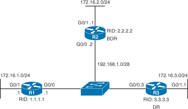
To make OSPF more efficient and scalable, OSPF supports hierarchical routing using areas, as shown in Figure 24-4.

There are four different types of OSPF routers, as shown in Figure 24-5.
![]() Internal router: This is a router that has all of its interfaces in the same area. All internal routers in an area have identical LSDBs. Internal routers are highlighted in Figure 24-5.
Internal router: This is a router that has all of its interfaces in the same area. All internal routers in an area have identical LSDBs. Internal routers are highlighted in Figure 24-5.
![]() Backbone router: This is a router in the backbone area. Generally, the backbone area is set to area 0. The backbone routers in Figure 24-5 are R1, R2, and the two internal routers in area 0.
Backbone router: This is a router in the backbone area. Generally, the backbone area is set to area 0. The backbone routers in Figure 24-5 are R1, R2, and the two internal routers in area 0.
![]() Area Border Router (ABR): This is a router that has interfaces attached to multiple areas. It must maintain separate LSDBs for each area it is connected to and can route between areas. The ABRs in Figure 24-5 are R1 and R2.
Area Border Router (ABR): This is a router that has interfaces attached to multiple areas. It must maintain separate LSDBs for each area it is connected to and can route between areas. The ABRs in Figure 24-5 are R1 and R2.
![]() Autonomous System Boundary Router (ASBR): This is a router that has at least one interface attached to an external internetwork, such as a non-OSPF network. An ASBR can redistribute routes into the OSPF network. The ASBR in Figure 24-5 is R1.
Autonomous System Boundary Router (ASBR): This is a router that has at least one interface attached to an external internetwork, such as a non-OSPF network. An ASBR can redistribute routes into the OSPF network. The ASBR in Figure 24-5 is R1.
Note
A router can be more than one type. For example, R1 is a backbone router, an ABR, and an ASBR.
Link-State Advertisements
Table 24-3 shows the types of link-state advertisements (LSAs).
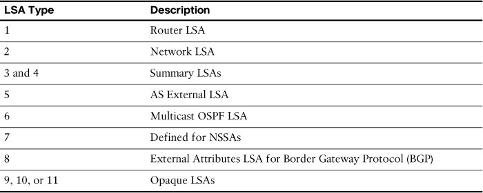
For the purposes of the CCNA exam, you should be familiar with the first five types:
![]() Type 1 (Router LSA): Describes the originating router, including router ID, directly connected network prefixes, and link types
Type 1 (Router LSA): Describes the originating router, including router ID, directly connected network prefixes, and link types
![]() Type 2 (Network LSA): Describes a network that has a DR and is sent by the DR; includes router IDs for the DR and all routers on the multi-access segment
Type 2 (Network LSA): Describes a network that has a DR and is sent by the DR; includes router IDs for the DR and all routers on the multi-access segment
![]() Type 3 (Summary LSA): Describes networks learned by type 1 LSAs and are flooded by ABRs into other areas
Type 3 (Summary LSA): Describes networks learned by type 1 LSAs and are flooded by ABRs into other areas
![]() Type 4 (Summary LSA): Used by ABRs to advertise an ASBR to other areas and provide a route to the ASBR
Type 4 (Summary LSA): Used by ABRs to advertise an ASBR to other areas and provide a route to the ASBR
![]() Type 5 (AS External LSA): Used by ASBRs to advertise an external network address such as a default route or networks learned from other routing protocols
Type 5 (AS External LSA): Used by ASBRs to advertise an external network address such as a default route or networks learned from other routing protocols
Configuring Multi-Area OSPFv2
The multi-area topology in Figure 24-6 is used in this topic to review multi-area OSPFv2 configuration.
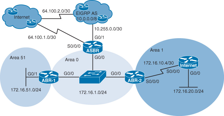
Multi-area OSPF is no more complex than single-area OSPF. The big difference is assigning the appropriate area ID in routing configuration. Example 24-11 shows the specific multi-area OSPFv2 configurations for the four routers in Figure 24-6.
Example 24-11 Multi-Area OSPFv2 Configurations
ASBR(config)# ip route 0.0.0.0 0.0.0.0 Serial0/0/0
ASBR(config)# ip route 10.0.0.0 255.0.0.0 GigabitEthernet0/1
ASBR(config)# router ospf 10
ASBR(config-router)# network 172.16.1.0 0.0.0.255 area 0
ASBR(config-router)# default-information originate
ASBR(config-router)# redistribute static
ABR-1(config)# router ospf 10
ABR-1(config-router)# network 172.16.51.0 0.0.0.255 area 51
ABR-1(config-router)# network 172.16.1.0 0.0.0.255 area 0
ABR-2(config)# router ospf 10
ABR-2(config-router)# network 172.16.10.4 0.0.0.3 area 1
ABR-2(config-router)# network 172.16.1.0 0.0.0.255 area 0
Internal(config)# router ospf 10
Internal(config-router)# network 172.16.10.4 0.0.0.3 area 1
Internal(config-router)# network 172.16.20.0 0.0.0.255 area 1
In the configuration for ASBR, there are two commands to redistribute routes into OSPF. The default-information originate command sets the default route to be propagated to all OSPF routers. The redistribute static command redistributes the static route for 10.0.0.0/8 into the OSPF network. These two commands make the router an ASBR.
Note
More advanced configurations are also possible for configuring route redistribution. However, that is beyond the scope of the CCNA exam.
The routing tables for a multi-area OSPFv2 configuration differ slightly, as shown in Example 24-12.
Example 24-12 Routing Table with External and Interarea Routes
ABR-1# show ip route
Codes: L - local, C - connected, S - static, R - RIP, M - mobile, B - BGP
D - EIGRP, EX - EIGRP external, O - OSPF, IA - OSPF inter area
N1 - OSPF NSSA external type 1, N2 - OSPF NSSA external type 2
E1 - OSPF external type 1, E2 - OSPF external type 2, E - EGP
i - IS-IS, L1 - IS-IS level-1, L2 - IS-IS level-2, ia - IS-IS inter area
* - candidate default, U - per-user static route, o - ODR
P - periodic downloaded static route
Gateway of last resort is 172.16.1.1 to network 0.0.0.0
O E2 10.0.0.0/8 [110/20] via 172.16.1.1, 01:47:19, GigabitEthernet0/0
172.16.0.0/16 is variably subnetted, 6 subnets, 3 masks
C 172.16.1.0/24 is directly connected, GigabitEthernet0/0
L 172.16.1.2/32 is directly connected, GigabitEthernet0/0
O IA 172.16.10.4/30 [110/65] via 172.16.1.3, 01:18:50, GigabitEthernet0/0
O IA 172.16.20.0/24 [110/66] via 172.16.1.3, 01:18:50, GigabitEthernet0/0
C 172.16.51.0/24 is directly connected, GigabitEthernet0/1
L 172.16.51.1/32 is directly connected, GigabitEthernet0/1
O*E2 0.0.0.0/0 [110/1] via 172.16.1.1, 01:47:19, GigabitEthernet0/0
Internal# show ip route ospf
O E2 10.0.0.0/8 [110/20] via 172.16.10.5, 01:38:45, Serial0/0/0
172.16.0.0/16 is variably subnetted, 5 subnets, 3 masks
O IA 172.16.1.0/24 [110/65] via 172.16.10.5, 01:38:45, Serial0/0/0
O*E2 0.0.0.0/0 [110/1] via 172.16.10.5, 01:38:45, Serial0/0/0
Internal#
The O IA routes are interarea routes. In the routing table for ABR-1, you can see that both O IA routes came from ABR-2. The O*E2 routes are external routes. By default, the cost for an external route is not incremented as it is advertised throughout the OSPF network. For example, the 10.0.0.0/8 external route has the same cost (20) on both the ABR-1 and Internal routers.
Study Resources
For today’s exam topics, refer to the following resources for more study.
