Day 8. WAN Connection Options and VPNs
CCNA 200-101 ICND2 Exam Topics
![]() Identify different WAN technologies
Identify different WAN technologies
Key Topics
Today is a whirlwind review of WAN connection options, virtual private networks (VPNs), and generic routing encapsulation (GRE). Because most of these exam topics are conceptual in nature, requiring no configuration skills, read through this review several times and refer to your study resources for more in-depth review.
WAN Connection Options
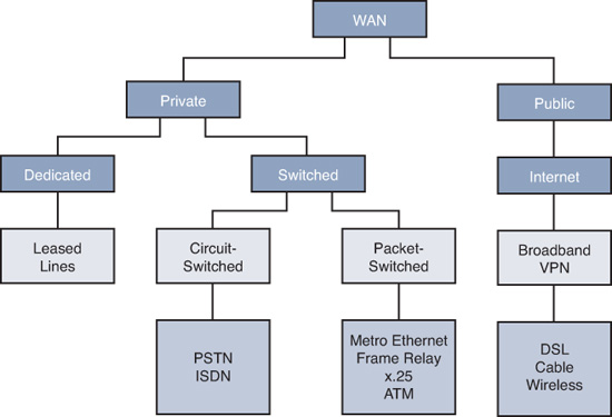
Many options for implementing WAN solutions are currently available. They differ in technology, speed, and cost. Figure 8-1 provides a high-level view of the various WAN link connection options, and the subsections that follow describe these options in more detail.
Dedicated Connection Options
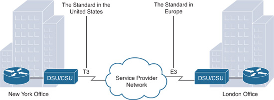
Also called leased lines, dedicated connections are pre-established point-to-point WAN connections from the customer premises through the provider network to a remote destination, as shown in Figure 8-2.
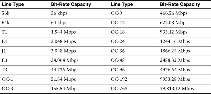
Leased lines are usually more expensive than switched services because of the dedicated, “always-on” cost of providing WAN service to the customer. The dedicated capacity removes latency and jitter and provides a layer of security because only the customer’s traffic is allowed on the link. Table 8-1 lists the available leased line types and their bit-rate capacities.
Circuit-Switched Connection Options
The two main types of circuit-switched connections are analog dialup and ISDN. Both technologies have a limited implementation base in today’s networks. However, they both may still be used in remote rural areas or other areas of the globe where more recent technologies are not yet available.
Analog dialup uses modems at very low-speed connections that might be adequate for the exchange of sales figures, prices, routine reports, email, or as an emergency backup link.
ISDN turns the local loop into a TDM digital connection, which enables it to carry digital signals that result in higher-capacity switched connections than analog modems. There are two types of ISDN interfaces:
![]() Basic Rate Interface (BRI): Provides two 64-kbps B channels for voice or data transfer and a 16-kbps D channel used for control signaling.
Basic Rate Interface (BRI): Provides two 64-kbps B channels for voice or data transfer and a 16-kbps D channel used for control signaling.
![]() Primary Rate Interface (PRI): Provides 23 B channels with 64 kbps and 1 D channel with 64 kbps in North America, for a total bit rate of up to 1.544 Mbps. Europe uses 30 B channels and 1 D channel, for a total bit rate of up to 2.048 Mbps.
Primary Rate Interface (PRI): Provides 23 B channels with 64 kbps and 1 D channel with 64 kbps in North America, for a total bit rate of up to 1.544 Mbps. Europe uses 30 B channels and 1 D channel, for a total bit rate of up to 2.048 Mbps.
Figure 8-3 illustrates the various differences between ISDN BRI and PRI lines.

Packet-Switched Connection Options
The most common packet-switching technologies used in today’s enterprise WANs include Metro Ethernet and Frame Relay. Legacy technologies include X.25 and ATM.
Metro Ethernet
Metro Ethernet (MetroE) uses IP-aware Ethernet switches in the service provider’s network cloud to offer enterprises converged voice, data, and video services at Ethernet speeds. Some benefits of Metro Ethernet include the following:
![]() Reduced expenses and administration: Enables businesses to inexpensively connect numerous sites in a metropolitan area to each other and to the Internet without the need for expensive conversions to ATM or Frame Relay
Reduced expenses and administration: Enables businesses to inexpensively connect numerous sites in a metropolitan area to each other and to the Internet without the need for expensive conversions to ATM or Frame Relay
![]() Easy integration with existing networks: Connects easily to existing Ethernet LANs
Easy integration with existing networks: Connects easily to existing Ethernet LANs
![]() Enhanced business productivity: Enables businesses to take advantage of productivity-enhancing IP applications that are difficult to implement on TDM or Frame Relay networks, such as hosted IP communications, VoIP, and streaming and broadcast video
Enhanced business productivity: Enables businesses to take advantage of productivity-enhancing IP applications that are difficult to implement on TDM or Frame Relay networks, such as hosted IP communications, VoIP, and streaming and broadcast video
Frame Relay
Figure 8-4 shows a simplified Frame Relay network.

Frame Relay was built on the legacy X.25 standard, but it differs from X.25 in several ways. Most importantly, it is a much simpler protocol, operating strictly at Layer 2, whereas X.25 provided Layer 3 services. Unlike X.25, Frame Relay implements no error checking or flow control. The simplified handling of frames leads to reduced latency, and measures taken to avoid frame buildup at intermediate switches help reduce jitter. Frame Relay offers data rates up to 4 Mbps, with some providers offering even higher rates. Frame Relay virtual circuits (VCs) are uniquely identified by a data-link connection identifier (DLCI), which ensures bidirectional communication from one DTE device to another. Most Frame Relay connections are permanent virtual circuits (PVCs) rather than switched virtual circuits (SVCs).
Internet Connection Options
Broadband connection options typically are used to connect telecommuting employees to a corporate site over the Internet. These options include digital subscriber line (DSL), cable, wireless, and Metro Ethernet.
DSL
DSL technology, shown in Figure 8-5, is an always-on connection technology that uses existing twisted-pair telephone lines to transport high-bandwidth data and provides IP services to subscribers.

Current DSL technologies use sophisticated coding and modulation techniques to achieve data rates of up to 8.192 Mbps. A variety of DSL types, standards, and emerging technologies exist. DSL is now a popular choice for enterprise IT departments to support home workers. Generally, a subscriber cannot choose to connect to an enterprise network directly.
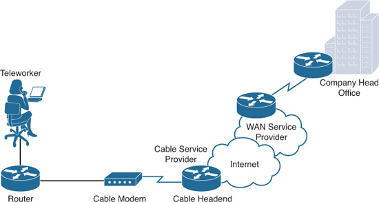
Cable Modem
Cable modems provide an always-on connection and a simple installation. Figure 8-6 shows how a subscriber connects a computer or LAN router to the cable modem, which translates the digital signals into the broadband frequencies used for transmitting on a cable television network.
Wireless
Until recently, the main limitation of wireless access has been the need to be within range of a wireless router or a wireless modem that has a wired connection to the Internet. The following new developments in broadband wireless technology are changing this situation:
![]() Municipal Wi-Fi: Many cities have begun setting up municipal wireless networks. Some of these networks provide high-speed Internet access for free or for substantially less than the price of other broadband services.
Municipal Wi-Fi: Many cities have begun setting up municipal wireless networks. Some of these networks provide high-speed Internet access for free or for substantially less than the price of other broadband services.
![]() WiMAX: Worldwide Interoperability for Microwave Access (WiMAX) is a new IEEE 802.16 technology that is just beginning to come into use. It provides high-speed broadband service with wireless access and provides broad coverage like a cell phone network rather than through small Wi-Fi hotspots.
WiMAX: Worldwide Interoperability for Microwave Access (WiMAX) is a new IEEE 802.16 technology that is just beginning to come into use. It provides high-speed broadband service with wireless access and provides broad coverage like a cell phone network rather than through small Wi-Fi hotspots.
![]() Satellite Internet: Typically used by rural users where cable and DSL are unavailable.
Satellite Internet: Typically used by rural users where cable and DSL are unavailable.
![]() Cellular service: Used to connect users and remote locations where no other WAN access technology is available. Common cellular access methods include 3G/4G (3rd generation and 4th generation) and LTE (Long-Term Evolution) cellular access.
Cellular service: Used to connect users and remote locations where no other WAN access technology is available. Common cellular access methods include 3G/4G (3rd generation and 4th generation) and LTE (Long-Term Evolution) cellular access.
Choosing a WAN Link Option
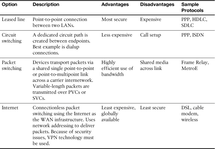
Table 8-2 compares the advantages and disadvantages of the various WAN connection options reviewed.
VPN Technology
A virtual private network (VPN) is an encrypted connection between private networks over a public network such as the Internet. Instead of using a dedicated Layer 2 connection such as a leased line, a VPN uses virtual connections called VPN tunnels, which are routed through the Internet from the company’s private network to the remote site or employee host.
![]() Cost savings: Eliminates the need for expensive dedicated WAN links and modem banks.
Cost savings: Eliminates the need for expensive dedicated WAN links and modem banks.
![]() Security: Uses advanced encryption and authentication protocols that protect data from unauthorized access.
Security: Uses advanced encryption and authentication protocols that protect data from unauthorized access.
![]() Scalability: Can add large amounts of capacity without adding significant infrastructure.
Scalability: Can add large amounts of capacity without adding significant infrastructure.
![]() Compatibility with broadband technology: Supported by broadband service providers so mobile workers and telecommuters can take advantage of their home high-speed Internet service to access their corporate networks.
Compatibility with broadband technology: Supported by broadband service providers so mobile workers and telecommuters can take advantage of their home high-speed Internet service to access their corporate networks.
Types of VPN Access
Two types of VPN access exist:
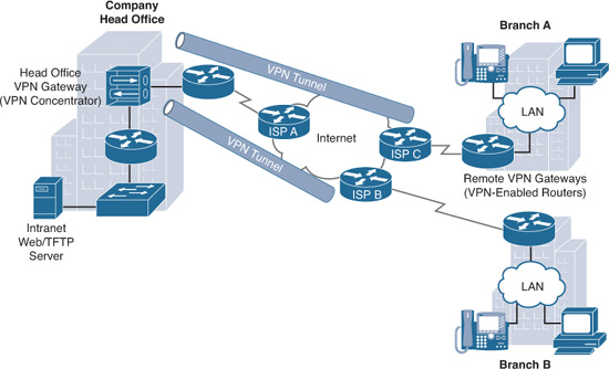
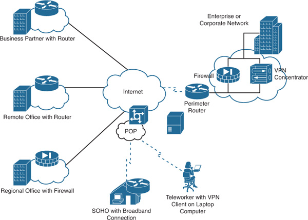
![]() Site-to-site VPNs: Connect entire networks to each other. For example, they can connect a branch office network to a company headquarters network, as shown in Figure 8-7. Each site is equipped with a VPN gateway, such as a router, firewall, VPN concentrator, or security appliance. In the figure, a remote branch office uses a site-to-site VPN to connect with the corporate head office.
Site-to-site VPNs: Connect entire networks to each other. For example, they can connect a branch office network to a company headquarters network, as shown in Figure 8-7. Each site is equipped with a VPN gateway, such as a router, firewall, VPN concentrator, or security appliance. In the figure, a remote branch office uses a site-to-site VPN to connect with the corporate head office.
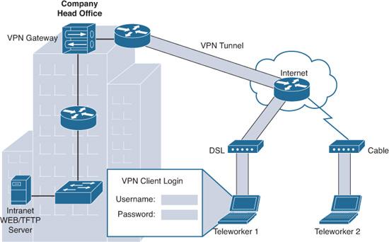
![]() Remote-access VPNs: Remote-access VPNs enable individual hosts, such as telecommuters, mobile users, and extranet consumers, to access a company network securely over the Internet, as shown in Figure 8-8. Each host typically has VPN client software loaded or uses a web-based client.
Remote-access VPNs: Remote-access VPNs enable individual hosts, such as telecommuters, mobile users, and extranet consumers, to access a company network securely over the Internet, as shown in Figure 8-8. Each host typically has VPN client software loaded or uses a web-based client.
VPN Components
Figure 8-9 illustrates a typical VPN topology. Components required to establish this VPN include the following:
![]() An existing enterprise network with servers and workstations
An existing enterprise network with servers and workstations
![]() A connection to the Internet
A connection to the Internet
![]() VPN gateways, such as routers, firewalls, VPN concentrators, and Adaptive Security Appliances (ASAs), that act as endpoints to establish, manage, and control VPN connections
VPN gateways, such as routers, firewalls, VPN concentrators, and Adaptive Security Appliances (ASAs), that act as endpoints to establish, manage, and control VPN connections
![]() Appropriate software to create and manage VPN tunnels
Appropriate software to create and manage VPN tunnels
Establishing Secure VPN Connections
VPNs secure data by encapsulating and encrypting it. With regard to VPNs, encapsulation and encryption are defined as follows:
![]() Encapsulation is also called tunneling because encapsulation transmits data transparently from source network to destination network through a shared network infrastructure.
Encapsulation is also called tunneling because encapsulation transmits data transparently from source network to destination network through a shared network infrastructure.
![]() Encryption codes data into a different format using a secret key, which is then used on the other side of the connection to decrypt.
Encryption codes data into a different format using a secret key, which is then used on the other side of the connection to decrypt.
VPN Tunneling
Tunneling uses three classes of protocols:
![]() Carrier protocol: The protocol over which information travels (Frame Relay, PPP, MPLS).
Carrier protocol: The protocol over which information travels (Frame Relay, PPP, MPLS).
![]() Encapsulating protocol: The protocol that is wrapped around the original data (GRE, IPsec, L2F, PPTP, L2TP).
Encapsulating protocol: The protocol that is wrapped around the original data (GRE, IPsec, L2F, PPTP, L2TP).
![]() Passenger protocol: The protocol over which the original data was carried (IPX, AppleTalk, IPv4, IPv6).
Passenger protocol: The protocol over which the original data was carried (IPX, AppleTalk, IPv4, IPv6).
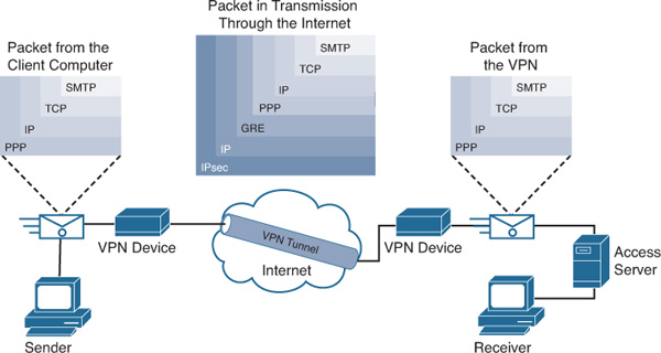
Figure 8-10 illustrates an email message traveling through the Internet over a VPN connection.
VPN Encryption Algorithms
The degree of security provided by any encryption algorithm depends on the key’s length. Some of the more common encryption algorithms and the length of the keys they use are as follows:
![]() Data Encryption Standard (DES) algorithm: Uses a 56-bit key, ensuring high-performance encryption. DES is a symmetric key cryptosystem.
Data Encryption Standard (DES) algorithm: Uses a 56-bit key, ensuring high-performance encryption. DES is a symmetric key cryptosystem.
![]() Triple DES (3DES) algorithm: A newer variant of DES that encrypts with one key, decrypts with a different key, and then encrypts a final time with another key.
Triple DES (3DES) algorithm: A newer variant of DES that encrypts with one key, decrypts with a different key, and then encrypts a final time with another key.
![]() Advanced Encryption Standard (AES): AES provides stronger security than DES and is computationally more efficient than 3DES. AES offers three key lengths: 128-, 192-, and 256-bit keys.
Advanced Encryption Standard (AES): AES provides stronger security than DES and is computationally more efficient than 3DES. AES offers three key lengths: 128-, 192-, and 256-bit keys.
![]() Rivest, Shamir, and Adleman (RSA): An asymmetric key cryptosystem. The keys use a bit length of 512, 768, 1024, or larger.
Rivest, Shamir, and Adleman (RSA): An asymmetric key cryptosystem. The keys use a bit length of 512, 768, 1024, or larger.
Symmetric encryption is when the encryption key and decryption key are the same. With asymmetric encryption, they are different.
Hashes
VPNs use a keyed hashed message authentication code (HMAC) data-integrity algorithm to guarantee a message’s integrity and authenticity without using any additional mechanisms.
The cryptographic strength of the HMAC depends on the cryptographic strength of the underlying hash function, on the key’s size and quality, and the size of the hash output length in bits. The two common HMAC algorithms are
![]() Message digest algorithm 5 (MD5): Uses a 128-bit shared secret key
Message digest algorithm 5 (MD5): Uses a 128-bit shared secret key
![]() Secure Hash Algorithm 1 (SHA-1): Uses a 160-bit secret key
Secure Hash Algorithm 1 (SHA-1): Uses a 160-bit secret key
Figure 8-11 shows an example using MD5 as the HMAC algorithm.
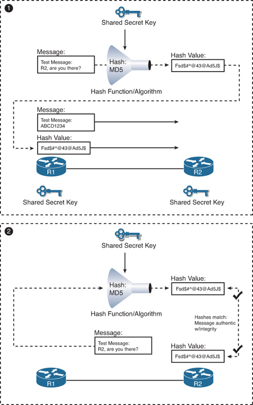
An HMAC has two parameters: a message input and a shared secret key known only to the message originator and intended receivers. In Figure 8-11, both R1 and R2 know the shared secret key. The process in Figure 8-11 uses the following steps:
1. R1 uses MD5 to perform the hashing function, which outputs a hash value. This hash value is then appended to the original message and sent to R2.
2. R2 removes the hash value from the original message, runs the same hash operation, and then compares its hash value with the hash value sent by R1. If the two hashes match, the data integrity has not been compromised.
VPN Authentication
The device on the other end of the VPN tunnel must be authenticated before the communication path is considered secure. The two peer authentication methods are as follows:
![]() Preshared key (PSK): A secret key is shared between the two parties using a secure channel before it needs to be used.
Preshared key (PSK): A secret key is shared between the two parties using a secure channel before it needs to be used.
![]() RSA signature: Uses the exchange of digital certificates to authenticate the peers.
RSA signature: Uses the exchange of digital certificates to authenticate the peers.
IPsec Security Protocols
IPsec spells out the messaging necessary to secure VPN communications but relies on existing algorithms. The two main IPsec framework protocols are as follows:
![]() Authentication Header (AH): Used when confidentiality is not required or permitted. AH provides data authentication and integrity for IP packets passed between two systems. It verifies the originators of any messages and that any message passed has not been modified during transit. AH does not provide data confidentiality (encryption) of packets. Used alone, the AH protocol provides weak protection. Consequently, it is used with the ESP protocol to provide data encryption and tamper-aware security features.
Authentication Header (AH): Used when confidentiality is not required or permitted. AH provides data authentication and integrity for IP packets passed between two systems. It verifies the originators of any messages and that any message passed has not been modified during transit. AH does not provide data confidentiality (encryption) of packets. Used alone, the AH protocol provides weak protection. Consequently, it is used with the ESP protocol to provide data encryption and tamper-aware security features.
![]() Encapsulating Security Payload (ESP): Provides confidentiality and authentication by encrypting the IP packet. Although both encryption and authentication are optional in ESP, at a minimum, one of them must be selected.
Encapsulating Security Payload (ESP): Provides confidentiality and authentication by encrypting the IP packet. Although both encryption and authentication are optional in ESP, at a minimum, one of them must be selected.
IPsec relies on existing algorithms to implement encryption, authentication, and key exchange. Figure 8-12 shows how IPsec is structured.

IPsec provides the framework, and the administrator chooses the algorithms used to implement the security services within that framework. As Figure 8-12 illustrates, the administrator must fill the four IPsec framework squares:
![]() Choose an IPsec protocol.
Choose an IPsec protocol.
![]() Choose the encryption algorithm that is appropriate for the desired level of security.
Choose the encryption algorithm that is appropriate for the desired level of security.
![]() Choose an authentication algorithm to provide data integrity.
Choose an authentication algorithm to provide data integrity.
![]() The last square is the Diffie-Hellman (DH) algorithm group, which establishes the sharing of key information between peers. Choose which group to use: DH1, DH2, or DH5.
The last square is the Diffie-Hellman (DH) algorithm group, which establishes the sharing of key information between peers. Choose which group to use: DH1, DH2, or DH5.
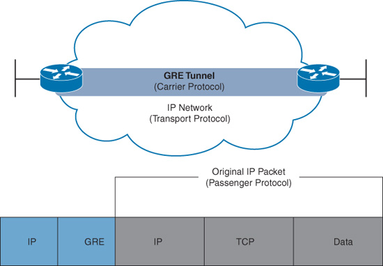
GRE Tunneling
Generic routing encapsulation (GRE) is one example of a basic, nonsecure, site-to-site VPN tunneling protocol. Typically, GRE is used to tunnel IP packets across the Internet, as shown in Figure 8-13. Let’s briefly review GRE characteristics and configuration.
GRE Characteristics
GRE has these characteristics:
![]() GRE is defined as an IETF standard (RFC 2784).
GRE is defined as an IETF standard (RFC 2784).
![]() In the outer IP header, 47 is used in the Protocol field to indicate that a GRE header will follow.
In the outer IP header, 47 is used in the Protocol field to indicate that a GRE header will follow.
![]() GRE encapsulation uses a Protocol Type field in the GRE header to support the encapsulation of any OSI Layer 3 protocol. Protocol types are defined in RFC 1700 as EtherTypes.
GRE encapsulation uses a Protocol Type field in the GRE header to support the encapsulation of any OSI Layer 3 protocol. Protocol types are defined in RFC 1700 as EtherTypes.
![]() GRE itself is stateless; by default, it does not include any flow-control mechanisms.
GRE itself is stateless; by default, it does not include any flow-control mechanisms.
![]() GRE does not include any strong security mechanisms to protect its payload.
GRE does not include any strong security mechanisms to protect its payload.
![]() The GRE header, together with the tunneling IP header indicated in the figure, creates at least 24 bytes of additional overhead for tunneled packets.
The GRE header, together with the tunneling IP header indicated in the figure, creates at least 24 bytes of additional overhead for tunneled packets.
GRE Configuration
In Figure 8-14, R1 is communicating with R2 through the Internet over a GRE tunnel.
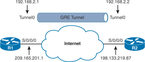
Notice that the addressing of the physical interfaces do not belong to the same subnet, but that the addressing for the Tunnel interface does belong to the same subnet.
To configure GRE, complete the following steps:
Step 1 Create a tunnel interface using the interface tunnel number command.
Step 2 Specify the tunnel source IP address.
Step 3 Specify the tunnel destination IP address.
Step 4 Configure an IP address for the tunnel interface.
Step 5 (Optional) Specify GRE tunnel mode as the tunnel interface mode with the tunnel mode gre ip command. GRE tunnel mode is the default tunnel interface mode for Cisco IOS Software.
Example 8-1 demonstrates the steps to configure GRE on R1 and R2. Notice that the OSPF configuration includes the tunnel subnet so that the routers can establish adjacency across the tunnel link.
Example 8-1 GRE Tunnel Configuration
R1(config)# interface Tunnel0
R1(config-if)# tunnel mode gre ip
R1(config-if)# ip address 192.168.2.1 255.255.255.0
R1(config-if)# tunnel source 209.165.201.1
R1(config-if)# tunnel destination 198.133.219.87
R1(config-if)# router ospf 1
R1(config-router)# network 192.168.2.0 0.0.0.255 area 0
R2(config)# interface Tunnel0
R2(config-if)# tunnel mode gre ip
R2(config-if)# ip address 192.168.2.2 255.255.255.0
R2(config-if)# tunnel source 198.133.219.87
R2(config-if)# tunnel destination 209.165.201.1
R2(config-if)# router ospf 1
R2(config-router)# network 192.168.2.0 0.0.0.255 area 0
Note
IPsec implementation is assumed in this example. However, IPsec configuration is beyond the scope of the CCNA/ICND2 exam.
To verify the GRE implementation, you should be able to ping R1 from R2 and R2 from R1, and they should have converged routing tables. In addition, you can use the show ip interface brief and show interface Tunnel commands, as shown in Example 8-2.
Example 8-2 Verifying the Tunnel Interface Is Up
R1# show ip interface brief | include Tunnel
Tunnel0 192.168.2.1 YES manual up up
R1# show interface Tunnel 0
Tunnel0 is up, line protocol is up
Hardware is Tunnel
Internet address is 192.168.2.1/24
MTU 17916 bytes, BW 100 Kbit/sec, DLY 50000 usec,
reliability 255/255, txload 1/255, rxload 1/255
Encapsulation TUNNEL, loopback not set
Keepalive not set
Tunnel source 209.165.201.1, destination 198.133.219.87
Tunnel protocol/transport GRE/IP
<output omitted>
