6 | Component Overview
The final section of this book, Part III, provides an in-depth component reference, examining in some detail the electronic devices most frequently encountered in audio electronic circuits. It discusses what they do, and how they are used, and it introduces some common applications and typical circuits in which they are found. It provides background information and guidance as to the use and the uses of these components.
In advance of this, and in order to facilitate the discussion presented in the current section, this present chapter opens Part II with a brief outline of the components presented in more detail in Part III. This provides some context to allow a better grasp of the material presented in the chapters which follow, delving into the practical topics which form the central theme of this book. A number of less common components are also introduced here, which are not expanded upon in the more detailed component chapters of Part III, but which do nonetheless merit a brief mention. There also exist many electronic devices too numerous and too specialised to be mentioned here at all.
Components covered in detail in Part III are given no more than a one or two line description here, while a short paragraph is provided on those components which are not further examined elsewhere. The devices presented here are introduced under the headings of passive components, semiconductor devices, vacuum tubes, transducers, and miscellaneous components. A more comprehensive list of components and general circuit elements is included in Appendix C, which covers such things as plugs, jacks, power sources, and meters, along with various other common schematic diagram symbols and conventions like ground points and wire connections.
Passive Components
A passive electronic component might be defined as one which does not require external power in order to operate, or one which does not use one signal in order to control another. The category is somewhat flexible but is generally taken to include at a minimum: resistors, capacitors, inductors, and transformers. Various other devices fit the criteria but may be more logically placed in another category.
Resistors – drop voltage and limit current.

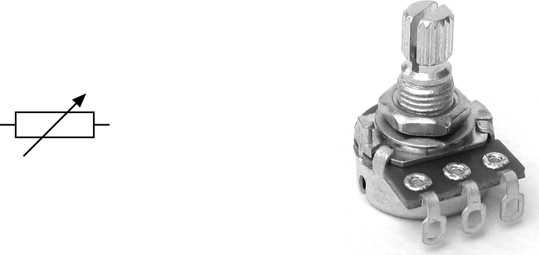
Variable Resistors – split the voltage across them. There are various types which may generally or specifically be referred to as: potentiometers, pots, faders, linear faders, trimmers, trim pots, and presets.
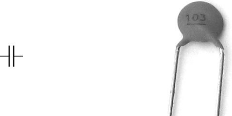
Capacitors – block low frequencies and pass high frequencies. A division worth noting is between polar and nonpolar types.
Inductors – pass low frequencies and block high frequencies. In many respects inductors can be considered to be the opposite of capacitors. In some applications an inductor is referred to as a choke.

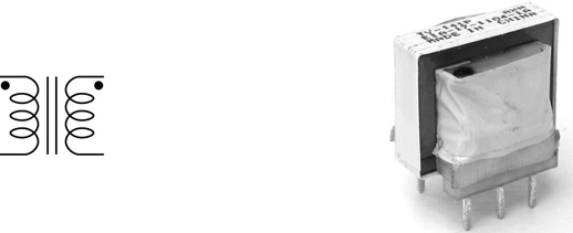
Transformers – transform voltages up and down.
Semiconductor Devices
In addition to the two commonest and most widely used semiconductor devices, the diode and the transistor, this section includes a variety of less commonly encountered discrete semiconductor based devices, as well as the more generic symbol often used to represent standard DIL integrated circuit packages. Many more specific IC symbols are also commonly encountered, some of which can be seen in Appendix C.
Photoresistors (aka light dependant resistors or LDRs) – have a resistance which varies depending on the amount of light striking them.

Thermistors – have a resistance which varies depending on the temperature of the device. Not often found in audio electronics, thermistors are commonly used in power electronics to detect overheating in a circuit or device. Thermistors come in two varieties depending on how the resistance changes with changing temperature. In positive temperature coefficient (PTC) devices the resistance rises as the temperature rises, and falls as the temperature falls. The PTC symbol has two arrows pointing in the same direction. In a negative temperature coefficient (NTC) thermistor the resistance falls as the temperature rises, and rises as the temperature falls. The NTC symbol has two arrows pointing in opposite directions (see Appendix C).

Varistors – are also referred to as MOVs (metal oxide varistors), or VDRs (voltage dependant resistors). These devices exhibit a very high resistance until a specified threshold voltage is applied, at which point the resistance falls sharply. A varistor might sometimes be more generically referred to as a TVS or transient voltage suppressor (c.f. GDT in Appendix C).

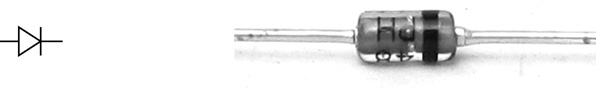
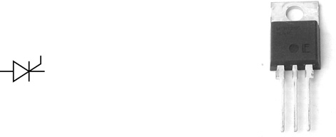
Diodes – allow current to flow in one direction but not the other. The diode is the most fundamental semiconductor device. There are lots of variants, for instance Zener diodes and Schottky diodes. Diodes are sometimes also called rectifiers.
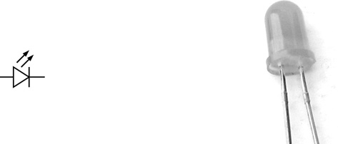
Light Emitting Diodes (LEDs) – are diodes which produce light.
Laser Diodes – produce coherent, columnated (i.e. laser) light, rather than the less controlled emissions from a standard LED. Laser diodes have a wide variety of applications including such things as CD players and laser pointers.

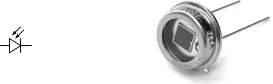
Photodiodes – are diodes in which the semiconductor junction is exposed to allow light to fall upon it. When illuminated, photodiodes generate electricity. This component is the basis of much solar cell technology. They can also be used in various light detection tasks from infrared to ultraviolet.
Transistors – amplify, buffer, and switch electrical signals. They come in many different types, shapes, and sizes.

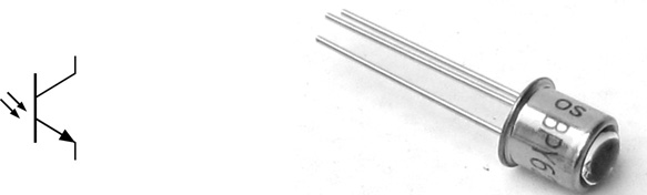
Phototransistors – are transistors which are controlled by light falling on an exposed semiconductor junction, rather than the usual electrical control signal applied to the base terminal. Phototransistors can be used as the detection element in CD and other optical players. Light reflected back from the disc strikes the exposed semiconductor junction and the resulting signal is interpreted in order to extract data from the disc medium.
DIACs, Thyristors, and TRIACs are related semiconductor devices which are often used in combination. One of their commonest applications is in the control circuitry used to implement adjustable lighting dimmers.
DIACs – are a form of semiconductor switch. They can conduct in both directions, but only once a threshold voltage or breakover voltage has been exceeded. DIAC stands for diode for alternating current. DIACs are two terminal devices and often look much like diodes. Sometimes a stripe around the middle of the body differentiates a DIAC from a diode (whose stripe is at one end, indication the cathode), but this is by no means always the case. The terms DIAC and SIDAC (silicon diode for alternation current) are sometimes used interchangeably, although they are not usually considered strictly the same thing. Convention differs between various sources.

Thyristors – or SCRs (silicon controlled rectifiers) can be thought of as diodes which will only start to conduct when they are triggered by a signal on their gate terminal (the third terminal, coming off at an angle). Smaller thyristors often look much like small signal transistors, but thyristors are often physically bigger devices used to control large electrical currents.
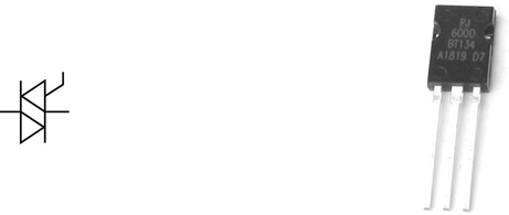
TRIACs – are much like the standard thyristor above, except that they operate in both directions (comparing the two symbols illustrates this point). Also like thyristors, TRIACs are three terminal devices, often physically similar to transistors. TRIAC stands for triode for alternating current.
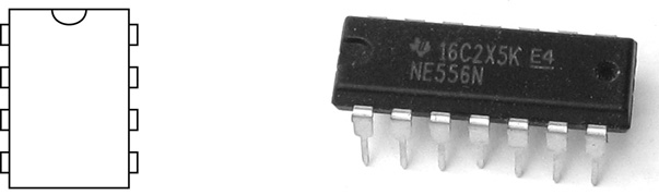
Integrated Circuits – provide a complete circuit in a prefabricated package. Opamps are probably the commonest and most obvious example in audio electronics, but there are thousands of others, both within the audio field and beyond.
Vacuum Tubes
Vacuum tubes (also called tubes, valves, or thermionic valves) were the forerunners of semiconductors (diodes, transistors, etc.). While generally rendered obsolete in the wider world of electronics, they still find favour in some audio applications because of the particular colour they can add to a sound signal. Only diode and triode tubes are mentioned here. Other more elaborate variations exist, but these are beyond the scope of the material presented in this book.
Diode Tubes – were the precursor to semiconductor diodes and, like these, they similarly allow current to flow in one direction but not the other.
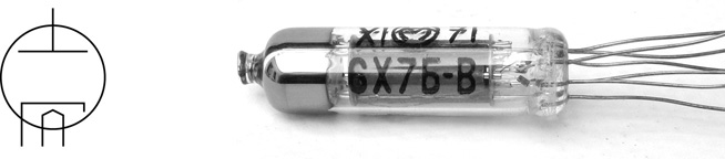
Triode Tubes – were the precursor to transistors, and like transistors they can be used to amplify, buffer, and switch electrical signals.

Transducers
Transducers transform signals from one form into another. Two broad subcategories are sensors and drivers. Other categories exist but are of less interest here. Sensors (including pickups and microphones) transform acoustic sound or mechanical vibrations into electrical signals. Drivers (most commonly, but not exclusively loudspeakers) transform electrical signals into mechanical movement (and then usually into sound).
Microphones – transform sound waves into electrical signals. The two commonest types are dynamic and condenser microphones, but there are others.

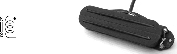
Coil Pickups (aka electric guitar pickups) – detect the vibration of metal guitar strings nearby. They consist of a coil of wire and a magnet.
Piezo Transducers – transform vibrations into electrical signals, and vice versa. They can be used as pickups or as drivers.

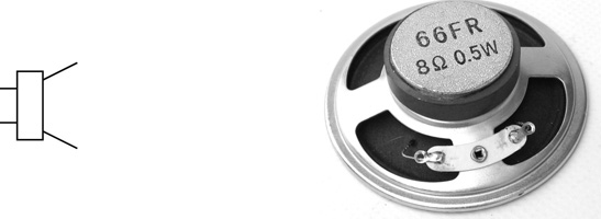
Loudspeakers – transform electrical signals into sound waves. The moving coil loudspeaker is the commonest. It consists of a coil of wire mounted in a magnetic field and attached to a cone.
Miscellaneous Components
There are many other electronic components available, however the focus here remains on those which are most likely to be encountered in audio electronics projects and audio technology in general.
Switches – provide the ability to route, connect, and select electrical signals.

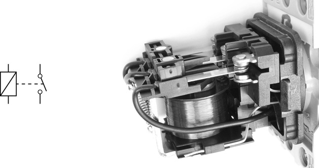
Relays – use an electrical signal to actuate a mechanical switch.
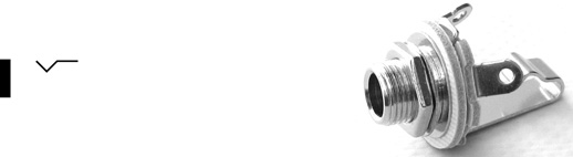
Jack Connectors – are amongst the commonest connector types used for audio. Electric guitar leads and headphone jacks are two examples.
RCA Connectors/Power Connectors – and other generic connector types may be represented by this symbol. Often the choice of connector to use in an application is more a packaging rather than an electrical decision.

Batteries – can be used to provide power to many of the circuits encountered here.

Meters – can be used to visually monitor and represent an electrical signal.

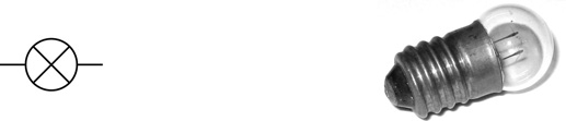
Lamps – are most obviously used for indicators and illuminators, but can also be used as control and stabilisation elements within circuits, in a similar fashion to thermistors.
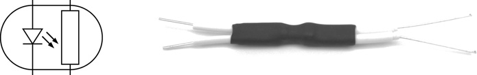
Optocouplers (aka opto-isolators) – provide electrical isolation between two parts of a circuit or system. In audio applications they are often employed as much for the distortion they introduce as for their intended purpose. The illustration shows a homemade optocoupler comprised of an LED and an LDR wrapped up in heat shrink tubing.
Reverb Pans – transmit their signal through long springs in order to introduce reverberation distortion into an audio signal.

References
K. Brindley. Starting Electronics. Newnes, 4th edition, 2011.
C. Motchenbacher and J. Connelly. Low-Noise Electronic System Design. Wiley, 1993.
RCA. Receiving Tube Manual. Radio Corporation of America, 1950.
M. Schultz. Grob’s Basic Electronics. McGraw-Hill, 11th edition, 2011.
TI. The TTL Data Book. Texas Instruments, 5th edition, 1982.
E. Young. Dictionary of Electronics. Penguin, 1985.