19 | Vacuum Tubes
Vacuum tubes (aka thermionic valves) were the forerunners of semiconductor devices such as diodes and transistors. There are quite a few different types of vacuum tubes but the discussion here is restricted to the commonest two variants, diode tubes, and triode tubes. These two types in particular correspond closely to the functionality of semiconductor diodes and transistors respectively.
The semiconductor alternatives have many advantages over their vacuum tube fore-bears – size, robustness, reliability, power consumption, and linearity of operation come to mind. However, for some applications – and to some ears – the different character which vacuum tubes can impart to an audio signal makes their sound a valuable tool in the audio electronics arsenal.
Principles of Operation
The goal of any electronic component is to exercise some control over how electricity flows in a circuit. Vacuum tubes achieve this control by virtue of the fact that heat can encourage electrons to leave the surface of a piece of metal and fly around in the surrounding space.
The basic principles upon which vacuum tubes operate are quite straightforward. These principles are illustrated in Figure 19.1. As a piece of metal is heated up, the electrons in the metal are given more energy. As such they fly around more vigorously, and as a result some electrons are able leave the surface of the metal and fly into space.
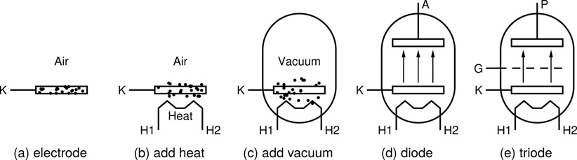
Figure 19.1 How vacuum tubes work. Start with an electrode (the cathode – K). Heat it with a heater (H1 and H2), and place it in an evacuated glass envelope (the vacuum tube). Add a second electrode (the anode – A, or plate – P) to make a diode. Add a third electrode for control (the grid – G) to make a triode.
If it is just a piece of metal sitting on the desk, they do not fly far before returning (various factors keeping them close by). If this heated piece of metal is enclosed inside an evacuated glass envelope (i.e. a vacuum tube), then one of the factors keeping the electrons close – the surrounding air molecules – is removed. The electrons can then stray a little farther, but still tend to return to base on account of their negative charge and the positive charge they leave behind – recall that opposites attract.
In order to make a diode tube from this starting point all that is needed is to insert a second piece of metal (aka electrode) into the evacuated glass envelope, and provide electrical connections to the two metal electrodes (Figure 19.1d). Now if a positive charge is applied to the second electrode then the electrons flying around in the vacuum see this positive charge as an inviting alternative destination, and some of them move across the gap between the two pieces of metal and fly headlong into the second electrode. This movement of electrons constitutes an electric current.
Note that it is only a one way process, because the second piece of metal is not being heated like the first, and so electrons are not nearly so likely to fly off the surface and into the vacuum between electrodes. Therefore if the second electrode is made more negative than the first, instead of being more positive, then no electrons cross the gap and no current flows.
This is exactly the action of a diode as described in Chapter 16 – diodes let current flow in one direction but not the other. The two terminals of a diode are commonly referred to as the cathode (the heated electrode where electrons emerge into the vacuum), and the anode (which can absorb electrons coming its way, but does not emit any).
The diode (or rectifier) is a very useful electronic component, but in order to arrive at a device in which one signal can be used in order to control another, a third electrode must be added to the mix, as in Figure 19.1e. This ‘control’ terminal is referred to as the grid, and with its addition the diode becomes a triode. The grid can be thought of as the means by which the valve is opened and closed. The valve is still only a one way street as before, but now the magnitude of the current flow in that forward direction can be controlled. This should be a very familiar basic scenario from the description of the action of transistors in Chapter 17.
The discussion presented above clearly illustrates the origin of the two general names for devices of this type: ‘vacuum tube’ because there is a glass tube with a vacuum inside, and ‘thermionic valve’ because heat is used to facilitate current flow.
Diode Tubes
The same one-line description which is used in Chapter 16 to characterise the semiconductor diode can also be seen as a valid description of the tube version of this component – diodes let current flow in one direction but not the other. When talking about semiconductor diodes, the next most important aspect of their behaviour is the forward bias voltage drop. Recall that a typical silicon diode requires approximately 0.6V to 0.7V across its terminals before it will start to conduct. This fact is used to good effect in the diode clipping circuits discussed in Chapter 16.
This forward bias voltage is required in order to overcome the depletion layer which develops at the p-n junction within these devices, as described in Chapter 3. One important difference between semiconductor and tube based diodes is that the tube diode requires no such bias voltage before it starts to conduct. As illustrated in the graph in Figure 19.2, the tube diode’s forward current Id starts to flow as soon as the voltage Vd rises above zero. As should be obvious from the graph, the relationship, although not very far from a straight line, is still decidedly nonlinear. As such a tube diode will impart some level of distortion onto any signal passing through it.
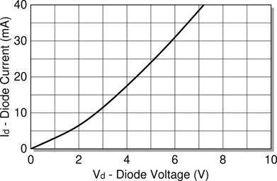
Figure 19.2 Typical diode valve i-v characteristic curve. This curve is for the EB91 dual diode, as pictured in Figure 19.6a, but is representative of the behaviour which can be expected from most diode tubes.
In common with their semiconductor based brethren, tube diodes are fundamentally two terminals devices, with an anode and a cathode at their positive and negative ends respectively. That being said, unlike semiconductor diodes, practical tube diodes have some additional connections. Typical circuit symbols used to indicate a diode tube in a schematic diagram are shown in Figure 19.3. As is often the case with such symbols, variations on the style illustrated here are regularly encountered, but the basic format is usually fairly close.
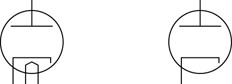
Figure 19.3 Circuit symbols for a diode (aka rectifier) valve.
As described above, all tubes require heating, and the heater connections may or may not be indicated on any given symbol, as is highlighted in the two variants shown here. The extra connections shown on the bottom of the symbol on the left represent the heater. See the discussion around Figure 7.6 (p. 99) for more on circuit diagram conventions surrounding the inclusion of vacuum tube heater connections.
When using tubes it is quite important to observe the correct supply voltage levels for heater connections. Running the heaters too low is likely to compromise the effective operation of the valves, although is generally not a major problem. On the other hand, supplying the heaters with a voltage in excess of that in the manufacturer’s spec-ifications is likely to significantly shorten a tube’s working life. Notice the very specific heater voltages quoted in Figure 19.4 and Figure 19.5. The level specified in both cases here (6.3V) is a common, but by no means universal heater voltage level.
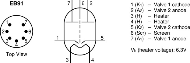
Figure 19.4 Pinout for an EB91 dual diode vacuum tube.
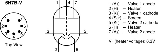
Figure 19.5 Pinout for a 6H7B-V dual diode vacuum tube.
The two devices whose details are provided in Figure 19.4 and Figure 19.5 are both what are referred to as dual diode vacuum tubes. This means that there are in fact two separate diode valves contained in the one device. as is often the case with such devices, a screen connection is provided, which is designed to isolate the two diodes from one another, so as to minimise the chances of crosstalk contamination allowing the signal in one diode to leak across into the other. This screen connection is usually bonded to the circuits ground plane.
The pair of connection points at the bottom of each diagram are for the heater, and the final two pairs represent the anode and cathode connections for each diode. Notice that the pin numbering is completely different between the two devices. They both have the same seven connections, but the ordering changes. It is always important to check the pinout for the specific device which you are using.
These two devices are also physically very different, as can be seen in Figure 19.6. The EB91 is a much broader tube and its pins are short and solid, designed to be plugged directly into a suitable tube socket. The 6H7B-V on the other hand is a very slim tube, and provides connections on much longer, flexible wires designed to be soldered directly into a circuit.
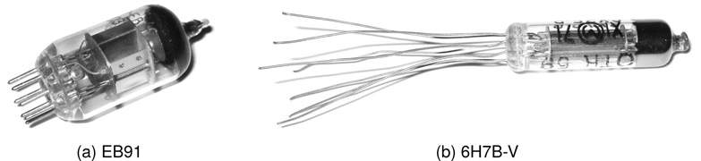
Figure 19.6 Two commonly found dual diode vacuum tubes.
In terms of circuits to experiment with, these devices can usefully be tried in any of the circuits provided for semiconductor diodes in Chapter 16 and elsewhere. Extra circuitry is needed in order to accommodate the required heater supply, and the screen should probably be grounded as described above, but otherwise these devices offer an interesting alternative to the more commonplace semiconductor approach. In particular, anywhere that diodes have been used explicitly for their clipping and distortion attributes, such a substitution might provide an interesting alternative.
Triode Tubes
As is the case with transistors, triodes can be used to amplify, buffer, and switch. The example characteristic curves shown in Figure 19.7, although quite different from the equivalent transistor curves given previously in Chapter 17, do share many general characteristics in common with those transistor curves.
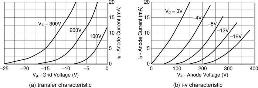
Figure 19.7 Typical triode valve characteristic curves. Those shown are for a 12AU7 dual triode valve (pictured in Figure 19.9).
The transfer characteristic in Figure 19.7a is most reminiscent of that of the JFET with its negative gate-source voltage range. Here a negative grid voltage takes its place, with the anode current reducing the more negative the grid voltage becomes.
The curves of the i-v characteristic in Figure 19.7b rise in a rather different fashion to their transistor cousins, and do not level off in the same way. These differences notwithstanding, the general behaviour of the family of graphs plotted here does represent a kind of control over the signals passing through the devices similar to that provided by transistors.
In fact, the most striking way in which these curves depart from the transistor’s characteristic curves is in the anode voltage levels quoted. While the maximum equivalent transistor voltages are typically in the low double digits, here the anode voltage is shown going up to 300 and even 400V, about twenty times the transistor maximums. This reflects a commonly recognised fact that tube amps tend to have some very high voltages knocking around inside them, which should be viewed with caution. This chapter steers clear of such hazards, and instead places its focus on a few low voltage possibilities for these devices, as described later.
Triode tubes are represented in schematic diagrams using symbols such as those shown in Figure 19.8. As was the case with the diode tube symbols introduced earlier, two variants are illustrated, one with and one without the requisite heater connections shown. As before, since many triodes come as a pair of valves in a single tube, and usually one set of heater connections can serve to heat both valves, it is often the case that one of each of the two symbols shown will appear in a schematic diagram, so as not to duplicate the required connections. The diagram for the tube booster circuit below illustrates this convention well.
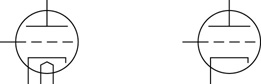
Figure 19.8 Circuit symbol for a triode valve.
As mentioned, triode tubes most often come in the form of a dual triode device, with two independent triodes housed in the same glass envelope. This is the case with the 12AU7 (aka ECC82) which is the triode illustrated in Figure 19.9. As is the case with most dual triodes, this tube has nine pins. Six give the grid, anode (or plate), and cathode of the two triodes (corresponding to the base, collector, and emitter of a BJT). The final three pins connect to the heater.
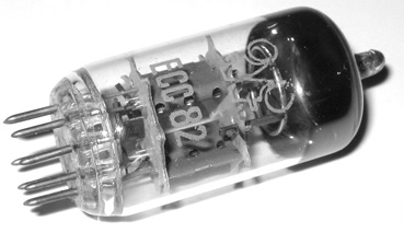
Figure 19.9 The 12AU7 (aka ECC82) dual triode vacuum tube.
Tube heater voltages are usually quite low. As indicated in Figure 19.10, the 12AU7 heater is designed to operate at either 12.6V or 6.3V, depending on how it is wired. Pin nine is a centre tap, with pins four and five connecting to either end of the heater. To use 12.6V connections should be made between pins four and five. To use 6.3V connections should be made between pin nine and either or both of pins four and five. The side of the heater to pin four services one valve, while the side to pin five services the other, as shown in Figure 19.10. It is far preferable to under supply the heater than it is to over supply it (as over voltage will lead to premature failure). Thus if for instance a nine volt supply is to be used to run the heater it should be connected between pins four and five, leaving pin nine unconnected.
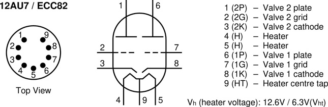
Figure 19.10 Pinout for a 12AU7 dual triode vacuum tube.
As referred to above, tubes themselves usually operate at very much higher plate voltages than the heater voltages just discussed, typically two or three hundred volts. It is however possible to squeeze some life out of a tube at much lower voltages. The material presented here deals only with these low voltage tube circuit designs. If venturing into higher voltage tube circuits tread carefully.
Low Voltage Tube Circuits
Standard (high voltage) tube circuits (most commonly seen today in guitar amps and other audio amplifiers) are a vast and complex subject area (see Jones, 2004; Pittman, 2004; Valley et al., 1948, for example). High voltages are involved, often in excess of the mains voltage powering the amp. Furthermore even the most basic tube amp kit is likely to cost at least several hundred euros, including tubes, power and output transformers, and various high voltage and high power handling components. In the spirit of the lo-fi, low cost audio electronics which this book embraces, such projects are left to others. It is however possible to have some fun with tubes running at low voltages too; definitely not where they were designed to operate but some life can still be coaxed out of them.
In the section on diode tubes above some suggestions are given as to experiments which can be conducted replacing semiconductor diodes in circuits with their vacuum tube counterparts. Perhaps no diode tubes are readily available but triode tubes such as the 12AU7 come easily to hand. If this is the case (and in similar fashion to the 2N7000 ‘MOSFET as a diode’ hack presented in Chapter 17) it is a simple matter to re-task a triode tube as a diode (Figure 19.11).

Figure 19.11 How to wire a triode valve to operate as a diode.
Clearly, the cathode must remain as the cathode, since the heater makes this the only source of electrons in the device. Various different connections of the remaining two terminals are possible (five in fact), but wiring together the grid and plate to form the anode of the diode is the best option. Other arrangements, such as, grid and cathode wired together can also be found suggested in various places, however the wiring shown in Figure 19.11 provides the best performance.
References
J. Hood. Valve and Transistor Audio Amplifiers. Newnes, 1997.
D. Hunter. The Guitar Amp Handbook. Backbeat Books, 2005.
M. Jones. Valve Amplifiers. Newnes, 3rd edition, 2003.
M. Jones. Building Valve Amplifiers. Newnes, 2004.
A. Pittman. The Tube Amp Book. Backbeat Books, 2004.
RCA. Receiving Tube Manual. Radio Corporation of America, 1950.
R. Tomer. Getting the Most out of Vacuum Tubes. Sams, 1960.
G. Valley, H. Wallman, and H. Wenetsky, editors. Vacuum Tube Amplifiers. McGraw-Hill, 1948.
B. Vogel. How to Gain Gain: A Reference Book on Triodes in Audio Pre-Amps. Springer, 2008.
G. Weber. Tube Amp Talk for the Guitarist and Tech. Kendrick Books, 1997.