D | Circuit Catalogue
This appendix gathers together all the major circuits presented throughout the book and collects them here along with example breadboard and stripboard layouts for each. As has been stressed previously, there is no one right answer when it comes to drafting a circuit layout, and the reader is strongly encouraged to have a go at laying out these circuits themselves.
Circuit Index
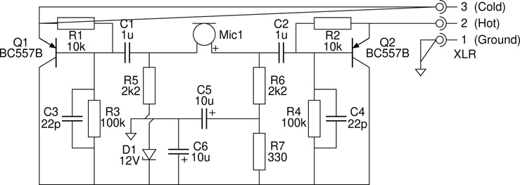
Phantom Powered Electret Microphone
Spring Reverb Drive and Recovery
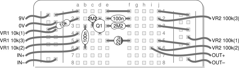
Breadboard Layouts
Stripboard Layouts
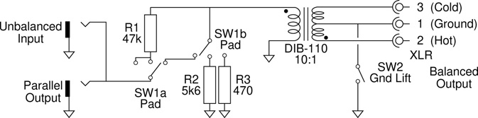
Passive DI Box
– see p. 253, Chapter 14 – Transformers
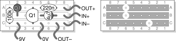
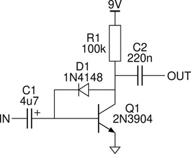
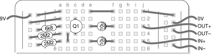
Single Transistor Fuzz
– see p. 302, Chapter 17 – Transistors
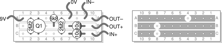
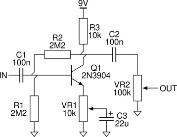
Simple BJT Booster
– see p. 302, Chapter 17 – Transistors
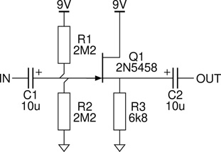
JFET Buffer
– see p. 308, Chapter 17 – Transistors
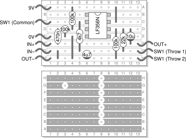
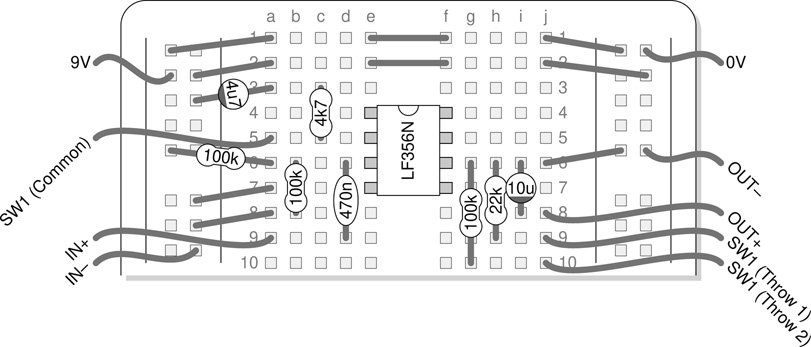
Opamp Preamp
– see p. 323, Chapter 18 – Integrated Circuits

Regulated Power Supply
– see p. 325, Chapter 18 – Integrated Circuits

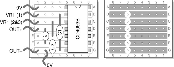
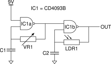
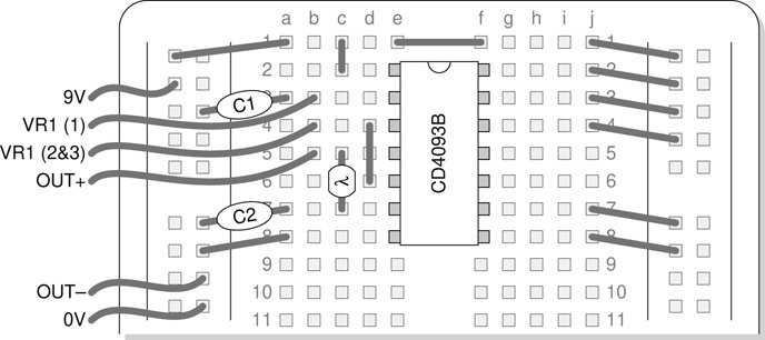
4093 Oscillator
– see p. 330, Chapter 18 – Integrated Circuits
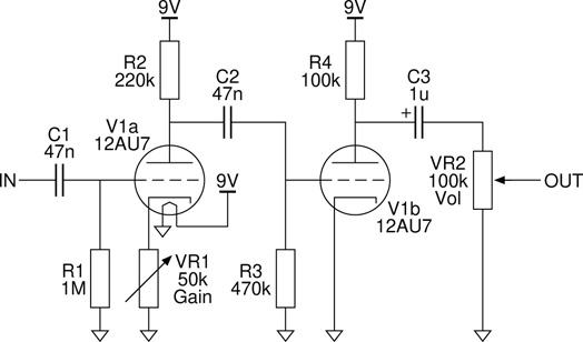
Low Voltage Tube Booster
– see p. 342, Chapter 19 – Vacuum Tubes
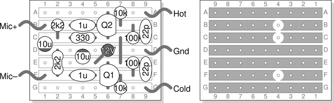
Phantom Powered Electret Microphone
– see p. 348, Chapter 20 – Audio Transducers
Spring Reverb Drive and Recovery
– see p. 366, Chapter 20 – Audio Transducers

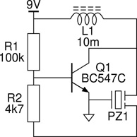
Piezo Oscillator
– see p. 365, Chapter 20 – Audio Transducers
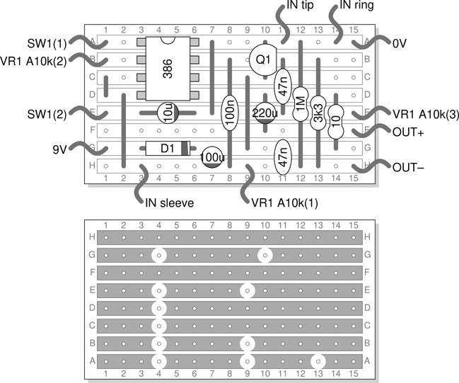
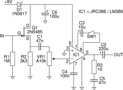
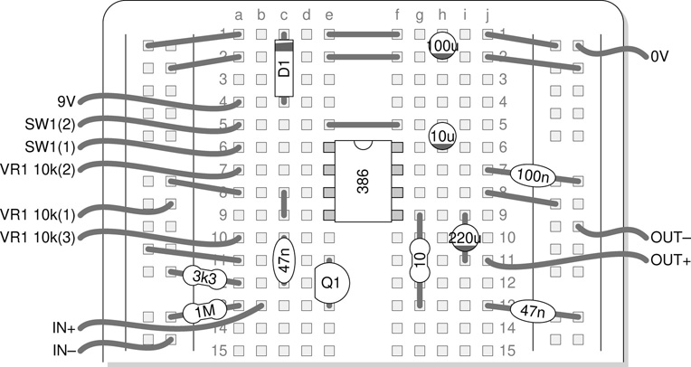
Low Power Audio Amplifier
– see p. 163, Chapter 11 – Projects
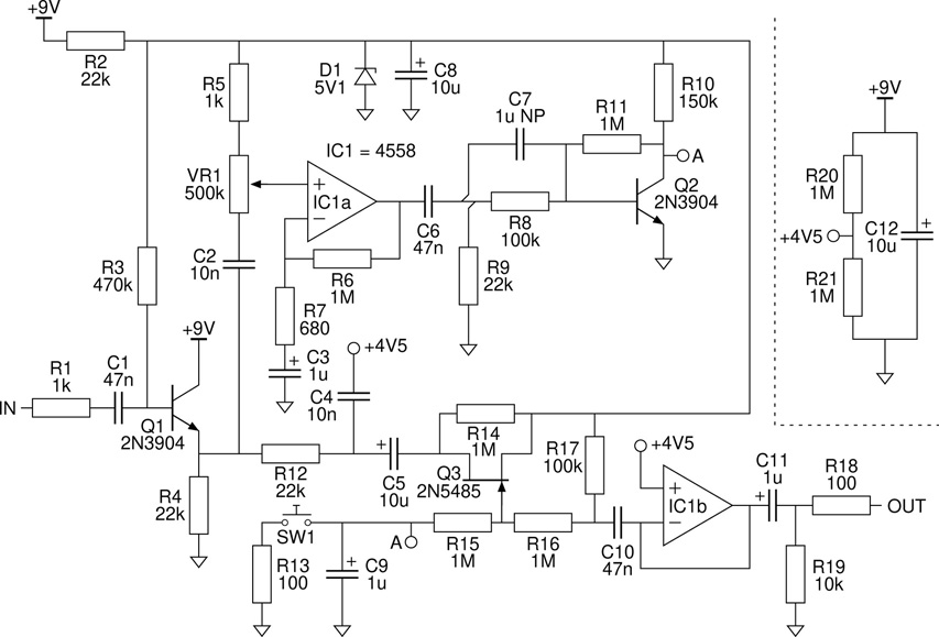
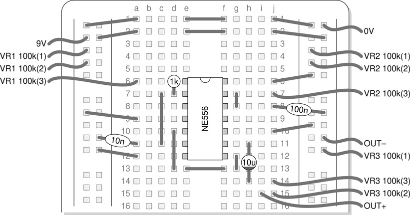
Stepped-Tone Generator
– see p. 174, Chapter 11 – Projects

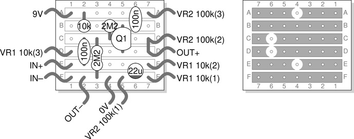
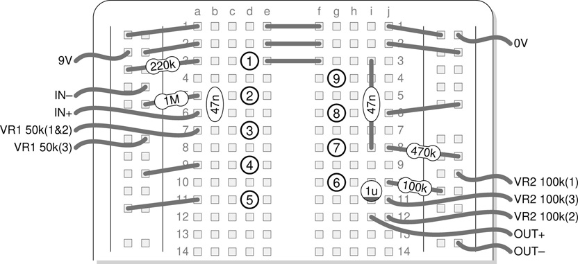
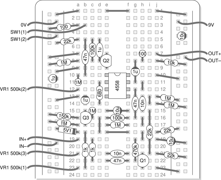
Modulation E˙ect
– see p. 180, Chapter 11 – Projects

Noise Gate
– see p. 115, Chapter 7 – Circuit Diagrams
Breadboard Layouts
– a breadboard layout of this circuit would consist of three resistors and a load of fly leads, and would not seem entirely worthwhile. The specified transformer has a suitable footprint for plugging in, but its legs are unlikely to fit into the breadboard holes and so it too would need fly leads soldered on. A stripboard layout, although also very simple, is furnished in the next section.


Stripboard Layouts
– the five stripboard holes where the transformer legs are inserted will need to be slightly enlarged. A quick touch with a rotary tool will do the trick.